Op Amp Applications Handbook Walt Jung, Editor
Op Amp Applications Handbook Walt Jung, Editor
Op Amp Applications Handbook Walt Jung, Editor

Create successful ePaper yourself
Turn your PDF publications into a flip-book with our unique Google optimized e-Paper software.
125<br />
Specialty <strong>Amp</strong>lifi ers<br />
buffers in series with each input (for example, using a precision dual op amp). But, this adds complexity to<br />
a simple circuit, and may introduce offset drift and nonlinearity.<br />
The second problem with this circuit is that the CMR is primarily determined by the resistor ratio matching,<br />
not the op amp. The resistor ratios R1/R2 and R1'/R2' must match extremely well to reject common mode<br />
noise—at least as well as a typical op amp CMR of ≥100 dB. Note also that the absolute resistor values are<br />
relatively unimportant.<br />
Picking four 1% resistors from a single batch may yield a net ratio matching of 0.1%, which will achieve<br />
a CMR of 66 dB (assuming R1 = R2). But if one resistor differs from the rest by 1%, the CMR will drop<br />
to only 46 dB. Clearly, very limited performance is possible using ordinary discrete resistors in this circuit<br />
(without resorting to hand matching). This is because the best standard off-the-shelf RNC/RNR style resistor<br />
tolerances are on the order of 0.1% (see Reference 1).<br />
In general, the worst-case CMR for a circuit of this type is given by the following equation (see References<br />
2 and 3):<br />
⎡1+ R2 R1⎤<br />
CMR( dB) = 20 log ⎢ ,<br />
4Kr ⎥<br />
Eq. 2-1<br />
⎣ ⎦<br />
where Kr is the individual resistor tolerance in fractional form, for the case where four discrete resistors<br />
are used. This equation shows that the worst-case CMR for a tolerance build-up for four unselected samenominal-value<br />
1% resistors to be no better than 34 dB.<br />
A single resistor network with a net matching tolerance of Kr would probably be used for this circuit, in<br />
which case the expression would be as noted in the fi gure, or:<br />
⎡1+ R2 R1⎤<br />
CMR( dB) = 20 log ⎢ Kr ⎥<br />
Eq. 2-2<br />
⎣ ⎦<br />
A net matching tolerance of 0.1% in the resistor ratios therefore yields a worst-case dc CMR of 66 dB using<br />
Eq. 2-2, and assuming R1 = R2. Note that either case assumes a signifi cantly higher amplifi er CMR (i.e.,<br />
>100 dB). Clearly for high CMR, such circuits need four single-substrate resistors, with very high absolute<br />
and TC matching. Such networks using thick/thin-fi lm technology are available from companies such as<br />
Caddock and Vishay, in ratio matches of 0.01% or better.<br />
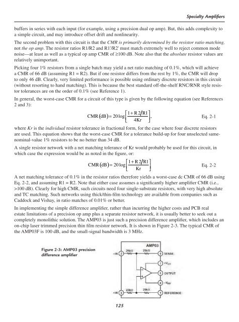
In implementing the simple difference amplifi er, rather than incurring the higher costs and PCB real<br />
estate limitations of a precision op amp plus a separate resistor network, it is usually better to seek out a<br />
completely monolithic solution. The AMP03 is just such a precision difference amplifi er, which includes an<br />
on-chip laser trimmed precision thin fi lm resistor network. It is shown in Figure 2-3. The typical CMR of<br />
the AMP03F is 100 dB, and the small-signal bandwidth is 3 MHz.<br />
Figure 2-3: AMP03 precision<br />
difference amplifi er