Op Amp Applications Handbook Walt Jung, Editor
Op Amp Applications Handbook Walt Jung, Editor
Op Amp Applications Handbook Walt Jung, Editor

Create successful ePaper yourself
Turn your PDF publications into a flip-book with our unique Google optimized e-Paper software.
Thus an ideal noninverting op amp stage gain is simply equal to 1/β, or:<br />
1<br />
G = β<br />
9<br />
<strong>Op</strong> <strong>Amp</strong> Basics<br />
Eq. 1-4<br />
This noninverting gain confi guration is one of the most useful of all op amp stages, for several reasons. Because<br />
V IN sees the op amp’s high impedance (+) input, it provides an ideal interface to the driving source. Gain<br />
can easily be adjusted over a wide range via R F and R G, with virtually no source interaction.<br />
A key point is the interesting relationship concerning RF and RG. Note that to satisfy the conditions of<br />
Eq. 1-2, only their ratio is of concern. In practice this means that stable gain conditions can exist over a<br />
range of actual RF – RG values, so long as they provide the same ratio.<br />
If RF is taken to zero and RG open, the stage gain becomes unity, and VOUT is then exactly equal to VIN. This special<br />
noninverting gain case is also called a unity gain follower, a stage commonly used for buffering a source.<br />
Note that this op amp example shows only a simple resistive case of feedback. As mentioned, the feedback<br />
can also be reactive, i.e., ZF, to include capacitors and/or inductors. In all cases, however, it must include a<br />
dc path, if we are to assume the op amp is being biased by the feedback (which is usually the case).<br />
To summarize some key points on op amp feedback stages, we paraphrase from Reference 2 the following<br />
statements, which will always be found useful:<br />
The summing point idiom is probably the most used phrase of the aspiring analog artifi cer, yet<br />
the least appreciated. In general, the inverting (−) input is called the summing point, while the<br />
noninverting (+) input is represented as the reference terminal. However, a vital concept is the fact<br />
that, within linear op amp applications, the inverting input (or summing point) assumes the same<br />
absolute potential as the noninverting input or reference (within the gain error of the amplifi er). In<br />
short, the amplifi er tries to servo its own summing point to the reference.<br />
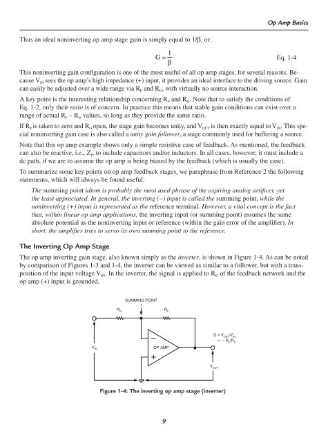
The Inverting <strong>Op</strong> <strong>Amp</strong> Stage<br />
The op amp inverting gain stage, also known simply as the inverter, is shown in Figure 1-4. As can be noted<br />
by comparison of Figures 1-3 and 1-4, the inverter can be viewed as similar to a follower, but with a transposition<br />
of the input voltage VIN. In the inverter, the signal is applied to RG of the feedback network and the<br />
op amp (+) input is grounded.<br />
V IN<br />
R G<br />
SUMMING POINT<br />
OP AMP<br />
G = V /V OUT IN<br />
= − R /R F G<br />
V OUT<br />
Figure 1-4: The inverting op amp stage (inverter)<br />
R F