Installation instructions Montageanweisung Stativgerät ... - Welch Allyn
Installation instructions Montageanweisung Stativgerät ... - Welch Allyn
Installation instructions Montageanweisung Stativgerät ... - Welch Allyn

You also want an ePaper? Increase the reach of your titles
YUMPU automatically turns print PDFs into web optimized ePapers that Google loves.
English Deutsch<br />
Figure / Abbildung<br />
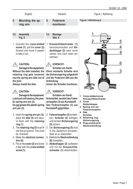
5 Mounting the spring<br />
arm<br />
5.2 Assembly<br />
Fig. 6<br />
1. Unscrew the cross-slotted<br />
screw (1), pull the cover (2)<br />
forward and move it upward<br />
to take it out.<br />
CAUTION-<br />
Damage to the equipment:<br />
Without the disk installed, the<br />
retaining ring gets loosened<br />
and the spring arm falls out of<br />
the joint.<br />
Always install the disk.<br />
CAUTION-<br />
Damage to the equipment:<br />
Lubricant will destroy the plastic<br />
spring arm pin (3).<br />
Do not grease the plastic spring<br />
arm pin (3).<br />
2. Insert the spring arm pin (3),<br />
place the disk (4) and secure<br />
them with the retaining<br />
ring (5).<br />
3. The retaining ring (5) must fit<br />
into the pin groove. This must<br />
be checked.<br />
4. Make the electrical connection<br />
(6).<br />
5. Put on the cover (2) and screw<br />
it fast with the cross-slotted<br />
screw (1).<br />
5 Federarm<br />
montieren<br />
5.2 Montage<br />
Abb. 6<br />
1. Kreuzschlitzschraube (1)<br />
herausschrauben und Abdeckkappe<br />
(2) nach vorne<br />
ziehen und nach oben abnehmen.<br />
VORSICHT-<br />
Schäden am Gerät:<br />
Ohne montierte Scheibe wird<br />
der Sicherungsring aufgedreht<br />
und der Federarm fällt aus der<br />
Anbindung.<br />
Immer die Scheibe montieren.<br />
VORSICHT-<br />
Schäden am Gerät:<br />
Schmierfett zerstört den Federarmzapfen<br />
(3) aus Kunststoff.<br />
Den Federarmzapfen (3) aus<br />
Kunststoff nicht fetten.<br />
2. Federarmzapfen (3) einstekken,<br />
Scheibe (4) auflegen<br />
und mit dem Sicherungsring<br />
(5) sichern.<br />
3. Der Sicherungsring (5) muß<br />
in die Zapfennut einrasten.<br />
Dies ist zu überprüfen.<br />
4. Elektrische Steckverbindung<br />
(6) herstellen.<br />
5. Abdeckkappe (2) aufsetzen<br />
und mit der Kreuzschlitzschraube<br />
(1) verschrauben.<br />
Figure / Abbildung 6<br />
�<br />
�<br />
1 Cross-slotted screw<br />
Kreuzschlitzschraube<br />
2 Cover<br />
Abdeckkappe<br />
3 Spring arm pin<br />
Federarmzapfen<br />
4 Disk<br />
Scheibe<br />
5 Retaining ring<br />
Sicherungsring<br />
6 Plug-socket joint<br />
Steckverbindung<br />
38 628 / 03 - 2006<br />
�<br />
�<br />
�<br />
�<br />
�<br />
Seite / Page 7