John N. Sorge Southern Company Services, Inc. PO - U.S. ...
John N. Sorge Southern Company Services, Inc. PO - U.S. ...
John N. Sorge Southern Company Services, Inc. PO - U.S. ...

You also want an ePaper? Increase the reach of your titles
YUMPU automatically turns print PDFs into web optimized ePapers that Google loves.
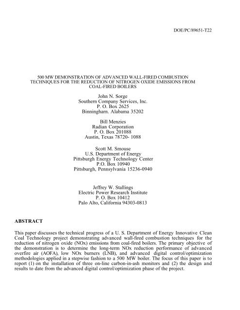
ABSTRACT<br />
DOE/PC/89651-T22<br />
500 MW DEMONSTRATION OF ADVANCED WALL-FIRED COMBUSTION<br />
TECHNIQUES FOR THE REDUCTION OF NITROGEN OXIDE EMISSIONS FROM<br />
COAL-FIRED BOILERS<br />
<strong>John</strong> N. <strong>Sorge</strong><br />
<strong>Southern</strong> <strong>Company</strong> <strong>Services</strong>, <strong>Inc</strong>.<br />
P. O. Box 2625<br />
Binningharn. Alabama 35202<br />
Bill Menzies<br />
Radian Corporation<br />
P. O. Box 201088<br />
Austin, Texas 78720- 1088<br />
Scott M. Smouse<br />
U.S. Department of Energy<br />
Pittsburgh Energy Technology Center<br />
P.O. Box 10940<br />
Pittsburgh, Pennsylvania 15236-0940<br />
Jeffrey W. Stallings<br />
Electric Power Research Institute<br />
P. O. Box 10412<br />
Palo Alto, California 94303-0813<br />
This paper discusses the technical progress of a U. S. Department of Energy Innovative Clean<br />
Coal Technology project demonstrating advanced wall-fired combustion techniques for the<br />
reduction of nitrogen oxide (NOx) emissions from coal-fired boilers. The primary objective of<br />
the demonstration is to determine the long-term NOx reduction performance of advanced<br />
overfire air (AOFA), low NOx burners (LNB), and advanced digital control/optimization<br />
methodologies applied in a stepwise fashion to a 500 MW boiler. The focus of this paper is to<br />
report (1) on the installation of three on-line carbon-in-ash monitors and (2) the design and<br />
results to date from the advanced digital control/optimization phase of the project.
INTRODUCTION<br />
This paper discusses the technical progress of one of the U.S. Department of Energy’s<br />
Innovative Clean Coal Technology (ICCT) projects demonstrating advanced combustion<br />
techniques for the reduction of nitrogen oxide (NOx) emissions from wall-fired boilers. The<br />
demonstration is being conducted on Georgia Power <strong>Company</strong>'s Plant Hammond Unit 4, a 500<br />
MW, pre-NSPS (New Source Performance Standards), wall-fired boiler. Plant Hammond is<br />
located near Rome, Georgia, northwest of Atlanta.<br />
The Hammond project is being managed by <strong>Southern</strong> <strong>Company</strong> <strong>Services</strong>, <strong>Inc</strong>. (SCS) on behalf<br />
of the project co-funders: The <strong>Southern</strong> <strong>Company</strong>, the U. S. Department of Energy (DOE), and<br />
the Electric Power Research Institute (EPRI). m addition to SCS, <strong>Southern</strong> includes the five<br />
electric operating companies: Alabama Power, Georgia Power, Gulf Power, Mississippi Power,<br />
and Savannah Electric and Power. SCS provides engineering and research services to the<br />
<strong>Southern</strong> electric system. The ICCT program is a jointly funded effort between DOE and<br />
industry to move the most promising advanced coal-based technologies to the commercial<br />
marketplace. The goal of ICCT projects is the demonstration of commercially feasible, advanced<br />
coal-based technologies that have already reached the "proof-of-concept" stage. The ICCT<br />
projects are jointly funded endeavors between the government and the private sector in which<br />
the industrial participant contributes at least 50 percent of the total project cost. The DOE is<br />
participating through the Office of Clean Coal Technology at the Pittsburgh Energy<br />
Technology Center (PETC).<br />
The primary objective of the demonstration is to determine the long-term NOx reduction<br />
performance of advanced overfire air (AOFA), low NOx burners (LNB), and advanced digital<br />
control/optimization methodologies applied in a stepwise fashion to a 500 MW boiler. Shortterm<br />
tests of each technology are also being performed to provide engineering information<br />
about emissions and performance trends [1,2,3,4].<br />
Following a brief unit and technology review, this paper focuses on the design and results to<br />
date from the advanced digital control/optimization phase of the project.<br />
UNIT AND TECHNOLOGY REVIEW<br />
Georgia Power <strong>Company</strong>'s Plant Hammond Unit 4 is a Foster Wheeler Energy Corporation<br />
(FWEC) opposed wall-fired boiler. rated at 500 MW gross, with design steam conditions of<br />
2500 psig and 1000/1000°F superheat/reheat temperatures, respectively. The unit was placed<br />
into commercial operation on December 14, 1970. Prior to the LNB retrofit in 1991, six FWEC<br />
Planetary Roller and Table type mills provided pulverized eastern bituminous coal (12,900<br />
Btu/lb. 3% VM, 53% FC, 72% 1.7% S, 1.4% N, 10% ash) to 24 pre-NSPS Intervane burners.<br />
The burners are arranged in a matrix of 12 burners (4W x 3H) on opposing walls with each mill<br />
supplying coal to four burners per elevation (Figure 1).<br />
During spring 1991 unit outage, the Intervane burners were replaced with FWEC controlled<br />
Flow/Split Flame (CF/SF) burners. In the CF/SF burner, secondary combustion air is divided<br />
between inner and outer flow cylinders. A sliding sleeve damper regulates the total secondary
Figure 1. Hammond Unit 4 Furnace Layout<br />
air flow entering the burner and is used to balance the burner air flow distribution. An<br />
adjustable outer register assembly divides the burner's secondary air into two concentric paths<br />
and also imparts some swirl to the air streams. The secondary air that traverses the inner path,<br />
flows across an adjustable inner register assembly that, by providing a variable pressure drop,<br />
apportions the flow between the inner and outer flow paths. The inner register also controls<br />
the degree of additional swirl imparted to the coal/air mixture in the near throat region. The<br />
outer air flow enters the furnace axially, providing the remaining air necessary to complete<br />
combustion. An axially movable inner sleeve tip provides a means for varying the primary air<br />
velocity while maintaining a constant primary flow. The split flame nozzle segregates the<br />
coal/air mixture into four concentrated streams each of which forms an individual flame when<br />
entering the furnace. This segregation minimizes mixing between the coal and the primary air,<br />
assisting in the staged combustion process.<br />
As part of this demonstration project, the unit was also retrofit with an Advanced Overfire Air<br />
(AOFA) system. The FWEC design diverts air from the secondary air ductwork and<br />
incorporates four flow control dampers at the corners of the overfire air windbox and four<br />
overfire air ports on both the front and rear furnace walls. Due to budgetary and physical<br />
constraints, FWEC designed an eight port AOFA system more suitable to the project and unit<br />
than the twelve port system originally proposed.<br />
The Unit 4 boiler was designed for pressurized furnace operation but was converted to<br />
balanced draft operation in 1977. The unit is equipped with a coldside ESP and utilizes two<br />
regenerative secondary air preheaters and two regenerative primary air heaters. During the<br />
course of the ICCT demonstration, the unit was retrofitted with six Babcock & Wilcox MPS 75<br />
mills (two each during the spring 1991, spring 1992, and fall 1993 outages).
REVIEW OF PRIOR TESTING<br />
Baseline, AOFA, LNB, and LNB+AOFA test phases have been completed (Table 1). Short-term<br />
and long-term baseline testing was conducted in an "as-found" condition from November 1989<br />
through March 1990. Following retrofit of the AOFA system during a four-week outage in<br />
spring 1990. the AOFA configuration was tested from August 1990 through March 1991. The<br />
FWEC CF/SF low NCx burners were then installed during a seven week outage starting on<br />
March 8, 1991 and continuing to May 5, 1991. Following optimization of the LNBs and<br />
ancillary combustion equipment by FWEC personnel, LNB testing was commenced during July<br />
1991 and continued until January 1992. Testing in the LNB+AOFA configuration was<br />
completed during August 1993. During both the LNB and LNB+AOFA, there were significant<br />
increases (when compared to baseline) in precipitator fly ash loading and gas flow rate and<br />
also, increases in fly ash LOI which adversely impacted stack particulate emissions and forced<br />
the unit to be load limited [5].<br />
Table 1. Project Schedule Phase<br />
Phase Description Date Status<br />
0 Pre-Award Negotiations 8/89 - 4/90 Completed<br />
1 Baseline Characterization 4/90 - 3/91 Completed<br />
2 Advanced Overfire Air Retrofit (AOFA) & Characterization 3/91 - 1/92 Completed<br />
3A Low Nox Burner Retrofit (LNB) & Characterization 1/92 - 8/93 Completed<br />
3B LNB+AOFA Characterization 1/92 - 8/93 Completed<br />
4 Digital Controls/Optimization Retrofit & Characterization 9/93 - 9/95 In Progress<br />
5 Final Reporting and Disposition 9/95 - 12/95 Later<br />
A summary of the baseline. AOFA, LNB, and LNB+AOFA long-term NOx emissions data for<br />
Hammond Unit 4 is shown in Figure 2. Baseline testing was performed in an "as-found"<br />
condition. For the AOFA, LNB, and LNB+AOFA test phases, following optimization of the unit<br />
by FWEC personnel. the unit was operated according to FWEC instructions provided in the<br />
design manuals. As shown. the AOFA, LNBs, and LNB+AOFA provide a long-term, full load,<br />
NOx reduction of 24, 48, and 68 percent, respectively. The load-weighted average of NOx<br />
emissions reductions was 14, 48, and 63 percent, respectively, for AOFA, LNBs, and<br />
LNB+AOFA test phases. Although the LNB plus AOFA NOx level represents a 67 percent<br />
reduction from baseline levels, a substantial portion of the incremental change in NOx<br />
emissions between the LNB and LNB+AOFA configurations is the result of operational<br />
changes and is not the result of the AOFA system [6].<br />
The time-weighted average of NOx emissions for the baseline, AOFA, LNB. LNB+AOFA test<br />
phases are shown in Table 2. Since NOx emissions are generally dependent on unit load, the<br />
NCx values shown in this table are influenced by the load dispatch of the unit during the<br />
corresponding test frame. Also shown in this table are the 30 day and annual achievable<br />
emission limits as determined during these test periods. The 30-day rolling average achievable<br />
emission limit is defined as the value that will be exceeded. on average, no more than one time<br />
per ten years. For the annual average, a compliance level of 95 percent was used in the<br />
calculation.
Figure 2. Long-Term NOx Emissions vs. Load Characteristic<br />
Table 2. Long-Term NOx Emissions<br />
Unit Configuration → Baseline AOFA LNB LNB+AOFA<br />
Parameter ↓ Mean RSD% Mean RSD, % Mean RSD, % Mean RSD, %<br />
Number of Daily Avg. Values 52 - 86 - 94 - 63 -<br />
Load (MW) 407 9.4 386 17.9 305 17.7 293 23.9<br />
Nox Emissions (lb/MBtu) 1.12 9.5 0.92 8.6 0.53 13.7 0.41 12.9<br />
O2 Level (percent at stack) 5.8 11.7 7.3 12.6 8.4 7.7 8.73 16.3<br />
Nox 30 Day AEL (lb/MBtu) 1.24 - 1.03 - 0.64 - 0.51 -<br />
Nox Annual AEL (lb/MBtu) 1.13 - 0.93 - 0.55 - 0.42 -<br />
EVALUATION OF ON-LINE CARBON-IN-ASH ANALYZERS<br />
A subsidiary goal of the Wall-Fired project is the evaluation of advanced instrumentation as<br />
applied to combustion control. Based on this goal, several on-line carbon-in-ash monitors are<br />
being evaluated as to their:<br />
• Reliability and maintenance,<br />
• Accuracy and repeatability, and<br />
• Suitability for use in the control strategies being demonstrated at Hammond Unit 4.<br />
Three units are currently installed at this site: (1) Applied Synergistics FOCUS, (2) CAMRAC<br />
Corporation CAM. and (3) Clyde-Sturdevant SEKAM. The SEKAM unit samples from two<br />
locations at the economizer outlet while the CAM unit samples from a single location at the<br />
precipitator inlet (Figure 3). The FOCUS unit is a non-extractive system that utilizes two<br />
cameras located above the nose of the furnace. The following paragraphs briefly describe these<br />
devices.
Figure 3. Sample Locations of CAM and SEKAM Carbon-in-Ash Analyzers<br />
Clvde-Sturdevant SEKAM<br />
The SEKAM unit was developed by the UK Central Electric Generating Board (CEGB). As a<br />
result of the dissolution of the CEGB, ownership of the SEKAM technology was eventually<br />
transferred to Clyde-Sturdevant Engineering. A sketch of the SEKAM system is shown in<br />
Figure 4. The basis of the SEKAM device is the measurement of capacitance of the fly ash<br />
sample using a Kajaani cell which was developed by the Finish firm Kajaani Limited. Ash<br />
collected from the flue gas stream (or other locations) is deposited in a glass chamber of<br />
rectangular cross section measuring 150x70x20 mm (5.9lx2.76x0.79 inches) placed between<br />
two capacitance sensors. The cell, flyash, and sensors are integrated into a circuit such that the<br />
output<br />
Figure 4. SEKAM General Arrangement
voltage of the circuit is a function of the measured capacitance. The device presumes a fixed<br />
relationship between the measured capacitance and carbon-in-ash. The installation at<br />
Hammond Unit 4 can sample from either the "A" or "B" side economizer outlet gas stream or<br />
from both probes simultaneously. It is expected that, except for short-term testing, the SEKAM<br />
will be configured to extract flue gas from both the "A" and "B" sides simultaneously thus<br />
shortening the sampling cycle time and improving the likelihood of obtaining a representative<br />
fly ash sample. Since the SEKAM device requires a relatively large fly ash sample<br />
(approximately 150 cm3 ~ 375 g), in order to reduce the overall sampling time, the system<br />
samples super-isokinetically. An exhauster is used to supply the motive force to transport the<br />
flue gas and fly ash. Super-isokinetic sampling can have either a positive or negative impact on<br />
overall sampling accuracy.<br />
The SEKAM system was installed on Hammond 4 during December 1994. Testing is now being<br />
conducted to verify the accuracy of the SEKAM system.<br />
CAMRAC CAM<br />
CAMRAC <strong>Company</strong>'s CAM (Carbon-Ash-Monitor) unit was developed during the 1980s by<br />
GAI Consultants (an affiliate of CAMRAC <strong>Company</strong>) with financial support from Allegheny<br />
Power <strong>Services</strong> Corporation, Duquesne Light <strong>Company</strong>, New England Power <strong>Services</strong>,<br />
NYSEG, <strong>Southern</strong> <strong>Company</strong> <strong>Services</strong>, Virginia Power, and EPRI. The CAM system uses the<br />
relative microwave absorbence between carbon and carbon-free fly ash to infer the carbon<br />
content of the sample. A schematic of a CAM system is shown in Figure 5. The installation at<br />
Hammond Unit 4 samples from one of twenty sample ports located at the inlet to the<br />
precipitator. The system has been designed such that vertical traverses of the flue gas stream<br />
can be conducted.<br />
Figure 5. CAMRAC General Arrangement
During long-term testing, fly ash samples will be drawn from a single location. For short-term<br />
testing, several sample ports and depths will be used so that a spatial distribution of the<br />
unburned carbon can be obtained.<br />
The CAM system was installed on Hammond 4 during February 1995. Testing is now being<br />
conducted to verify the accuracy of the CAM system.<br />
Applied Synergistics FOCUS<br />
The Applied Synergistic's FOCUS Unburned Carbon Module is a non-intrusive real-time device<br />
which provides a timely, continuous on-line indication of unburned carbon in fly ash. The<br />
device is based on the premise that unburned carbon particles and carbon laden ash particles<br />
exiting the furnace will be hotter than the surrounding background gases, carbon-free ash<br />
particles, and support structures, and therefore the carbon-laden particles will be higher emitters<br />
of radiant energy, especially in the infrared range. The primary sensing elements are one or<br />
more near infrared video cameras installed on the furnace. The hotter particles will be seen as<br />
white spots traversing the camera(s) field of view and these images are processed to determine<br />
the number of traverses in counts per minute. The assumption is then made that the carbon-inash<br />
(on a percent basis) is a function of these counts and unit load. Two cameras are utilized at<br />
Hammond 4. A sketch of the system is shown in Figure 6.<br />
The FOCUS Unburned Carbon Module was installed during July 1995. Testing of this device<br />
for calibration and verification purposes has begun.<br />
Figure 6. FOCUS General Arrangement
PHASE 4 - ADVANCED CONTROLS / OPTIMIZATION<br />
As a result of the installations of the low N(lx combustion systems at Hammond 4, combustion<br />
optimization has become significantly more difficult than prior to these retrofits. This added<br />
difficulty is a result of several factors including:<br />
• Heightened concern and awareness of combustion conditions as a result of the passage of<br />
the 1990 Amendments to the Clean Air Act,<br />
• <strong>Inc</strong>reased sensitivity of combustion conditions to process adjustments, and<br />
• Additional complexity and more independent tuning adjustments.<br />
The objective of this scope addition to the project at Plant Hammond is to evaluate and<br />
demonstrate the effectiveness of advance digital control/optimization methodologies as applied<br />
to the NOx abatement technologies installed at this site (LNB and AOFA). The major tasks for<br />
this project addition include: (1) design and installation of a distributed digital control system<br />
(DCS), (2) instrumentation upgrades, (3) advanced controls/optimization design and<br />
implementation, and (4) characterization of the unit both before and after activation of the<br />
advanced strategies. Major milestones for this phase of the Wall-Fired Project are shown in<br />
Table 3.<br />
Table 3. Advanced Controls / Optimization Major Activities<br />
Milestone Status<br />
Digital control system design, configuration, and installation Completed<br />
Digital control system startup Completed<br />
Instrumentation upgrades Completed<br />
Advanced controls/optimization design In Progress<br />
Characterization of the unit prior to activation of advanced strategies Scheduled 8/94 - 4/95<br />
Characterization of the unit following activation of advanced strategies Scheduled Summer 1995<br />
Combustion optimization is the procedure by which NOx reduction, combustion performance,<br />
and safety are balanced to achieve or approach a predetermined goal. In most instances, the<br />
goals are defined in terms of performance inequality constraints mutually agreed to by the<br />
burner vendor and the utility such as:<br />
• NOx - Reduce to below guarantee value and/or compliance limit.<br />
• Fly ash loss-on-ignition (LOI) - Hold below guarantee value and/or state imposed state<br />
utilization limit.<br />
• Boiler performance -Maintain above the guarantee value.<br />
These goals may be defined for one or more operating conditions. Only when all constraint<br />
goals are clearly met, will further NOx optimization be performed. Due the complexity of the<br />
combustion process, optimization is formidable unless the goals are lax. Combustion
optimization for the low NOx burners with advanced oveffire air is considerably more difficult<br />
than that required for setup of turbulent burners alone. This added difficulty is a result of the<br />
increase in the number of adjustments and sensitivity of these burners to operating conditions<br />
(Table 4).<br />
Table 4. Combustion Tuning Control Points at Hammond 4<br />
Pre-LNB+AOFA Retrofit Post-LNB+AOFA Retrofit<br />
Burners Burners<br />
Sleeve registers (24) Sleeve registers (24)<br />
Secondary air Tip Positions (24)<br />
Windbox balancing dampers Inner registers (24)<br />
Mill Biasing Outer register (24)<br />
Advanced overfire air<br />
Can-in-can dampers (8)<br />
Flow control dampers (4)<br />
Secondary air<br />
Windbox balancing dampers<br />
Boundary air<br />
Mill Biasing<br />
Generally, optimization requires that the unit be taken out of economic dispatch and run at fullload<br />
for much of the optimization period. After balancing the secondary air flows, the burner<br />
optimization process is accomplished by adjusting the inner registers, outer registers, slide<br />
nozzles, and sleeve dampers while monitoring NO x, O 2, and CO at the economizer outlet. When<br />
possible. burner adjustments of the same class (the classes being inner register, outer register.<br />
slide nozzle, or sleeve damper) are moved in unison to a nominal, optimized position. Only<br />
when flow and/or combustion irregularities dictate, are individual dampers adjusted from this<br />
nominal position. The adjustments to the sleeve dampers, inner registers, outer registers, and tip<br />
position are made during the burner optimization process and thereafter remain fixed unless<br />
changes in plant operation or equipment condition dictate further adjustments. The normal<br />
FWEC practice is to supply actuators on the sleeve dampers only. Optimization is performed<br />
for full-load operation and performance is checked at lower loads. Because of the constraints<br />
of the equipment and optimization methodology, the combustion process can be optimized for<br />
one operating condition (load, fuel condition, air distribution, etc.) and therefore is sub-optimal<br />
for all others.<br />
Unlike SO 2 emissions which are primarily a function of the sulfur content of the fuel, NOx<br />
emissions are highly dependent on a number of parameters. Nitrogen oxides (NOx) are formed<br />
in combustion processes through the thermal fixation of atmospheric nitrogen in the<br />
combustion air producing "thermal NOx" and the conversion of chemically bound nitrogen in<br />
the fuel producing "fuel NOx". NOx emissions can theoretically be reduced by lowering: (1) the<br />
primary flame zone O 2 level, (2) the time of exposure at high temperatures, (3) the combustion<br />
intensity, and (4) primary flame zone residence time. NOx emission rates are strongly influenced<br />
by the apportionment of the air to the burners and AOFA system.
An example of the interdependencies and conflicting goals which must be considered can be<br />
seen in Figure 7. As shown, as excess air (or equivalently, excess oxygen) decreases, Nox<br />
decreases<br />
while LOI increases. High LOI values are indicative of poor combustion and therefore poor<br />
boiler performance. Also, on units which sell: their fly ash (Hammond 4 does not at this time), an<br />
increase in fly ash LOI can change the fly ash from a marketable commodity to an undesirable<br />
byproduct. A decision must be made as to what is the optimum operating condition based on<br />
economic and environmental considerations. Similar compromises must also be made when<br />
optimizing boiler efficiency. In this case, the optimum operating condition is clear as long as the<br />
performance index is defined as boiler efficiency and other parameters (such as Nox emissions)<br />
are not considered. Conflicting objectives such as these have been observed on Hammond<br />
Unit 4. As shown in Figure 8, the NOx production rate is an increasing function of the excess<br />
oxygen level while fly ash LOI is a decreasing function. This data was collected during the<br />
short-term low NOx burner tests.<br />
In addition to variations with excess oxygen levels and load, NOX emissions also vary<br />
significantly during long-term operation and it is evident that a number of uncontrolled and<br />
unidentified variables greatly influence NOX production. These influencing variables are<br />
believed to be mill operating conditions (primary air temperatures, air/fuel ratios, flows, grind,<br />
and moisture), secondary air non-uniformity (air register settings, forced draft fan bias, and<br />
windbox pressure differential), coal variability, etc. As shown in Figure 9, NOx long-term<br />
variability at Hammond Unit 4 for the LNB plus AOFA test phase was approximately 0.07<br />
lb/MBtu at full load, increasing to 0.3 lb/MBtu at minimum load. As can be seen, there are<br />
significant differences in the NOx emission characteristics although no changes in burner<br />
adjustments or operating procedures were made during this time frame. A potential goal of any<br />
on-line optimization program installed at this site would be to drive NOx emissions down to the<br />
lower percentile and beyond.<br />
Figure 7. Typical Tradeoffs in Boiler Optimization
Figure 8. Nox and LOI vs. Excess Oxygen (Nox vs. LOI Tests)<br />
Figure 9. Long-Term NOx Emissions During LNB Pius AOFA Test Phase
Generic Nox Control Intelligent System<br />
The optimization methodology to be demonstrated at Hammond is the Generic NOx Control<br />
Intelligent System (GNOCIS) whose development is being funded by a consortium consisting<br />
of the Electric Power Research Institute, PowerGen, The <strong>Southern</strong> <strong>Company</strong>, U.K. Department<br />
of Trade and Industry, and U.S. Department of Energy [7]. The objective of the GNOCIS<br />
project is to develop fan on-line enhancement to existing digital control systems that will result<br />
in reduced Nox emissions, while meeting other operational constraints on the unit (principally<br />
heat rate and other regulated emissions). The main contractors for the development of GNOCIS<br />
are PowerGen and <strong>Southern</strong> <strong>Company</strong> <strong>Services</strong>. Commercializers for North America are SCS<br />
and Radian Corporation. In its role as commercializer, Radian is already deeply involved in the<br />
demonstrations in the U.S. PowerGen. and one other as yet unnamed organization will be the<br />
commercializers in Europe.<br />
The core of the system is a neural-network model of the combustion characteristics (such as<br />
NOx emissions and fuel efficiency) of a boiler that reflects both short-term and longer-term<br />
shifts in boiler emission characteristics. The software applies an optimizing procedure to<br />
identify the best set points for the plant. The recommended set points are conveyed to the<br />
plant operators via the DCS or, at the plants discretion, the set points can be implemented<br />
automatically without operator intervention. The software incorporates sensor validation<br />
techniques and is able to operate during plant transients (i.e. load ramping, fuel disturbances,<br />
and others). Figure 10 shows the major elements of GNOCIS.<br />
Figure 10. Major Elements of GNOCIS<br />
Following an initial feasibility study in which several promising methodologies were evaluated.<br />
a software package from Pavilion Technologies was selected to fulfill the “core” technology<br />
role in GNOCIS, i.e. to form the basis of the process and control models necessary to perform<br />
on-line optimization. The models are created from data collected from long-term, normal<br />
operation, augmented as necessary by short-term testing.
GNOCIS methodology is now undergoing testing at PowerGen's Kingsnorth Unit 1 (a 500<br />
MW tangentially-fired unit with an ICL Level 3 Low NOx Concentric Firing System) and<br />
Alabama Power's Gaston Unit 4 (a 250 MW B&W unit with B&W XCL low-NOx burners), the<br />
results of which have been reported elsewhere [8].<br />
Customization of GNOCIS at Hammond is now underway. The major activities associated with<br />
the GNOCIS installation at Hammond 4 are:<br />
• Digital Control System Design, Configuration and Installation<br />
• Instrumentation Upgrades<br />
• Pre-Installation Testing<br />
• Model and Optimization Strategy Development<br />
• Post-Installation Testing<br />
These elements are discussed in the following paragraphs.<br />
Digital Control System Design, Configuration , and Installation<br />
An integral part of Phase 4 of the project was the design and installation of a digital control<br />
system (DCS) to be the host of the advanced control/optimization strategies being developed.<br />
Prior to the installation of this DCS, Hammond Unit 4 utilized a pneumatic boiler control system<br />
which would be unsuitable for a closed-loop implementation of GNOCIS, therefore it was<br />
necessary to upgrade this system. SCS Engineering and Georgia Power had overall<br />
responsibility for the following major activities associated with this task:<br />
• Preliminary engineering.<br />
• Procurement,<br />
• Detail engineering,<br />
• Digital control. system configuration, and<br />
• Installation and checkout.<br />
In total, the digital control system was configured for 2352 input/output points consisting of<br />
572 analog inputs, 116 analog outputs, 1032 digital inputs, and 632 digital outputs with the<br />
balance being allocated spares. This system is designed such that the I/O is fully distributed and<br />
operator interaction with the digital control system is almost exclusively through the operator<br />
display--there are no benchboard mounted manual/auto stations or switches.<br />
An overview of the digital control system is shown in Figure 11. Based on a competitive<br />
evaluation, a Foxboro I/A system was selected for installation. The milestones in the design.<br />
installation, and startup of the Hammond Unit 4 digital control system are shown in Table 5.<br />
As part of this project. the control room was modified to accept the new Unit 4 digital control<br />
system. Pre-existing Unit 4 benchboards were removed and replaced with a CRT based control<br />
panel. In addition to the upgrades to Unit 4, Georgia Power has upgraded Unit 3 and is also<br />
considering upgrading the digital control systems on Units I and 2. Digital control system and<br />
control room modifications for Units 1. 2, and 3 are not a part of the Wall-Fired Project.
The Unit 4 DCS has been interfaced with the other DCS's at the site. Unit 3, Unit 4, and<br />
Electrical DCS systems are connected through a dual-redundant IEEE 802.3 (Ethernet) local<br />
area network (LAN). Through this LAN, the three DCSs are able to share process information<br />
and graphics. If for some reason either the A or B LAN fails, all DCSs can maintain normal<br />
operation. An additional benefit of these LANs are the ability to share costly resources such as<br />
engineering consoles historical drives, etc. In addition to the inter-DCS network, the Unit 4<br />
DCS (and the others also), are connected through a router to the plant's token-ring PC<br />
engineering and administrative LAN and the corporate wide area network (WAN) (Figure 12).<br />
The latter enables remote access of process data and facilitates software maintenance. A Sun<br />
Sparcstation 5, hosting the GNOCIS software, is connected to this network. The router isolates<br />
the DCS from the plant LAN and company WAN.<br />
Figure 11. Hammond Unit 4 DCS Overview<br />
Table 5. DCS Installation Milestones<br />
Date Milestone<br />
June 1992 • Begin preliminary engineering<br />
August 1992 • Issue request for proposals for digital control system<br />
February 1993 • Foxboro l/A system received at SCS<br />
April 1993 • Issue purchase order to Foxboro<br />
June 1993 • Start detail engineering<br />
June 1993 • Begin configuration<br />
January 1994 • Configuration complete<br />
• Start checkout<br />
February 1994 • Foxboro l/A system shipped to Plant Hammond for installation<br />
May 1994 • Installation complete<br />
June 1994 • Unit Startup
Pre-Installation Testing<br />
Figure 12. Hammond Plant Network<br />
One prerequisite of a GNOCIS installation is the availability of substantial and high quality<br />
process data from the host site. At Hammond, this need was amplified in that a goal of the<br />
project is to comprehensively test the performance of GNOCIS. Short-term diagnostic testing<br />
was conducted during August 1944 and March 1995, and more comprehensive performance<br />
testing was undertaken in November 1994. The primary objectives of these tests were to:<br />
• Re-characterize the unit following a number of combustion modifications during the most<br />
recent outage,<br />
• Establish relationships between control variables and measured variables.<br />
• Establish the impact of off-design operational settings, and<br />
• Augment the database used for training of GNOCIS models.<br />
Based on these tests, NOx emissions were found to be approximately 0.43 lb/MBtu -slightly<br />
higher that 0.40 lb/MBtu observed during Phase 3B testing -- with corresponding fly ash losson-ignition<br />
levels near 8 percent. This latter value is similar to what had been observed during<br />
Phase 3B testing.<br />
Long-term collection of data to be used for training for this phase has been in progress since<br />
summer 1994. Although this represents a large volume of information and satisfactory GNOCIS
models could potentially be developed using a subset (one to two months) of this long-term<br />
normal operating data only, it was felt that by obtaining process information in off-design<br />
conditions, the combustion models would be more robust. The need to conduct additional<br />
testing depends on the variability of data contained in the training set. Unfortunately, although<br />
having many advantages otherwise, digital control systems tend to create highly correlated<br />
data in which it is difficult to ascertain emission sensitivities to a number of potential control<br />
parameters. One example where this is likely is in mill loadings. Typically, when in service and<br />
in automatic, all mills are constrained to equal fuel flows and therefore, unless there is some<br />
variability, models can not be created based on process data alone, that can estimate the impact<br />
of individual mill flows on important combustion properties such as NOx emissions. The shortterm<br />
test suite was planned to artificially create the off-design operating conditions that may<br />
not be seen during normal unit operation.<br />
Model and Optimization Strategy Development<br />
Retrieval of process data from the digital control system is now in progress and initial modeling<br />
efforts have begun. The first step in the design process is the development of suitable<br />
predictive models. An example of the results from a typical non-linear predictive model of NOx<br />
and carbon-in-ash are shown in Figures 13 and 14, respectively. In this example, the inputs to<br />
the network were coal flows, excess O 2, and overfire air flows. The data collected from the DCS<br />
and used in training was five minute averages. Steps which could have been taken to improve<br />
the prediction capabilities include the addition of more process data and time averaging. Due to<br />
the long response time of the on-line carbon-in-ash devices, especially at reduced loads, the<br />
modeling of this parameter is generally much more difficult than modeling NOx emissions.<br />
Although predictive models are useful in a number of circumstances what is required of<br />
GNOCIS are control models. Considerations in control model development are sensitivities of<br />
model outputs (such as boiler efficiency and NOx emissions) to available inputs, and control<br />
points readily changeable by the operator or through the DCS.<br />
Design of the control strategy for Hammond 4 is now in progress. As a starting point, it is<br />
planned to used the control variables as shown in Table G. The control variables in the first tier<br />
will be implemented initially, and, if successful, additional variables from the subsequent tiers<br />
will be considered if their inclusion improves the performance of the system significantly.<br />
Software hooks have been designed into the DCS to facilitate the incorporation of these<br />
signals into the control logic.<br />
DISCLAIMER<br />
This report was prepared as an account of work sponsored by an agency of the United States<br />
Government. Neither the United States Government nor any agency [hereof, nor any of their<br />
employees, makes any warranty. express or implied, or assumes any legal liability or responsibility<br />
for the accuracy, completeness, or usefulness of any information, apparatus, product, or process<br />
disclosed, or represents that its use would not infringe privately owned rights. Reference herein to<br />
any specific commercial product, process, or service by trade name, trademark, manufacturer, or<br />
otherwise does not necessarily constitute or imply its endorsement, recommendation, or favoring<br />
by the United States Government or any agency thereof. The views and opinions of authors<br />
expressed herein do not necessarily state or reflect those of the United States Government or any<br />
agency thereof.
Figure 13. NOx Predictive Model<br />
Figure 14. Carbon-in-Ash Predictive Model
Table 6. Planned Control Variables<br />
Advisory Supervisory<br />
Parameter of Interest Controlled Parameter Mode Mode<br />
Open-Loop Close-Loop<br />
First Tier<br />
Overall Furnace Air/Fuel Ratio Excess O 2 Bias Y Y<br />
Overall Furnace Staging AOFA Flow (4) Y Y<br />
AOFA Distribution AOFA Flow (4) Y Y<br />
Mill Biasing Mill Coal Flow (6) Y Y<br />
Mills-in-Service Mill Coal Flow (6) Y Advise<br />
Second Tier<br />
AOFA Distribution AOFA Can Dampers (8) Y Y<br />
Furnace Secondary Air Distribution Burner Sleeve Dampers by Banks (8) Y Y<br />
Third Tier<br />
Furnace Secondary Air Distribution Burner Sleeve Dampers (24) Y Y<br />
Using the combustion models thus developed, predictions can be made as to the benefits that<br />
can be obtained by the application of GNOCIS. For example, as shown in Figure 15, predicted<br />
CIA levels near 5 percent were achieved using optimized control setpoints (fuel biasing, excess<br />
O 2, overfire air flow rates). The corresponding recommended excess 02 levels are shown in<br />
Figures 16 and 17. Although the recommended setpoints may not be feasible for actual longterm<br />
operation, this scenario does at least lend hope that opportunities may be present for<br />
significant CIA reductions. Again, these are predicted results, and although encouraging,<br />
they need to be substantiated with thorough plant testing.<br />
Figure 15. Control Model - Predicted CIA Output (Preliminary)
Post-Installation Testing<br />
Figure 16. Control Model - Recommended Right Excess O 2 (Preliminary)<br />
Figure 17. Control Model - Recommended Left Excess O2 (Preliminary)<br />
Testing of GNOCIS is scheduled to commence summer 1995 in both open-loop-advisory and<br />
close-loop-supervisory modes. The test program is now scheduled for completion during third<br />
quarter 1995.
SUMMARY<br />
Work is still in progress at Hammond Unit 4. A summary of the current status and plans for this<br />
site are as follows:<br />
• Long-term data set collected and it is now being filtered to remove bad and irrelevant data,<br />
• Predictive and control model development is in progress,<br />
• The GNOCIS software is being installed on the Sun Sparcstation 5 and interfaced with the<br />
DCS,<br />
• Operator displays are being developed and integrated into the operator consoles, and<br />
• Open- and closed-loop testing of GNOCIS at Hammond 4 is scheduled to commence<br />
summer 1995.<br />
ACKNOWLEDGMENTS<br />
The authors wish to gratefully acknowledge the support and dedication of the following<br />
personnel: Mr. Ernie Padgett and Mr. W. C. Dunaway, Georgia Power <strong>Company</strong>, and Mr. Scott<br />
Allison, Mr. Bob Kelly, Mr. Mike Nelson, <strong>Southern</strong> <strong>Company</strong> <strong>Services</strong>, for their coordination of<br />
the design and retrofit efforts, and Mr. Jose Perez. Instrumentation Specialist from Spectrum<br />
Systems, <strong>Inc</strong>. We would also like to recognize the following companies for their outstanding<br />
testing and data analysis efforts: Energy Technology Consultants, <strong>Inc</strong>., Flame Refractories, <strong>Inc</strong>.,<br />
Innovative Combustion Technologies, <strong>Southern</strong> Research Institute, and W. S. Pitts Consulting.<br />
Finally, the support from Mark Perakis, EPRI Project Manager, is greatly appreciated.<br />
REFERENCES<br />
1. 500 MW Demonstration of Advanced Wall-Fired Combustion Techniques for the<br />
Reduction of Nitrogen Oxide Emissions from Wall-Fired Boilers - Phase I Baseline<br />
Tests. <strong>Southern</strong> <strong>Company</strong> <strong>Services</strong>, Birmingham, AL: 1991.<br />
2. 500 MW Demonstration of Advanced Wall-Fired Combustion Techniques for the<br />
Reduction of Nitrogen Oxide Emissions from Wall-Fired Boilers - Phase 2 Overfire<br />
Tests <strong>Southern</strong> <strong>Company</strong> <strong>Services</strong>, Birmingham, AL: 1992.<br />
3 500 MW Demonstration of Advanced Wall-Fired Combustion Techniques for the<br />
Reduction of Nitrogen Oxide Emissions from Wall-Fired Boilers - Phase 3A Low Nox<br />
Burner Tests. <strong>Southern</strong> <strong>Company</strong> <strong>Services</strong>, Birmingham, AL: 1994.<br />
4 500 MW Demonstration of Advanced Wall-Fired Combustion Techniques for the<br />
Reduction of Nitrogen Oxide Emissions from Wall-Fired Boilers - Phase 3B Low<br />
Burner plus Advanced Overfire Air Tests. <strong>Southern</strong> <strong>Company</strong> <strong>Services</strong>, Birmingham,<br />
AL: 1995.<br />
5. 500 MW Demonstration of Advanced Wall-Fired Combustion Techniques for the
Reduction of Nitrogen Oxide (NOx) Emissions from Coal Fired Boilers - Technical<br />
Progress Report - Third Quarter 1991. <strong>Southern</strong> <strong>Company</strong> <strong>Services</strong> <strong>Inc</strong>., Birmingham.<br />
AL: 1992.<br />
6. <strong>Sorge</strong>, J., Wilson, S., "500 MW Demonstration of Advanced Wall Fired Combustion<br />
Techniques for the Reduction of Nitrogen Oxide (NOx) Emissions from Coal Fired<br />
Boilers," Third Annual Clean Coal Technology Conference, September 6-8,1984,<br />
Chicago, Illinois.<br />
7. Holmes, R., Squires, R., <strong>Sorge</strong>, J., Chakraborty, R., McIlvried, T., "Progress Report on the<br />
Development of a Generic NOx Control Intelligent System (GNOCIS), " EPRI 1994<br />
Workshop on NQx Controls for Utility Boilers, May 11-13, 1994, Scottsdale, Arizona.<br />
8. Holmes, R., Mayes, I., Irons, R., <strong>Sorge</strong>, J. N., Stallings, J. W., "GNOCIS An Update of the<br />
Generic NOx Control Intelligent System," EPRI/EPA 1995 Joint Symposium on<br />
Stationary NOx Control, May 15-19, 1995, Kansas City, Missouri.