

Solar Passive design: - High Performance Commercial Buildings in ...
Solar Passive design: - High Performance Commercial Buildings in ...
Solar Passive design: - High Performance Commercial Buildings in ...

Create successful ePaper yourself
Turn your PDF publications into a flip-book with our unique Google optimized e-Paper software.
SOLAR PASSIVE DESIGN FEATURES<br />
<strong>Solar</strong> <strong>Passive</strong> <strong>design</strong>:<br />
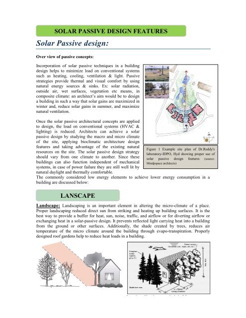
Over view of passive concepts:<br />
Incorporation of solar passive techniques <strong>in</strong> a build<strong>in</strong>g<br />
<strong>design</strong> helps to m<strong>in</strong>imize load on conventional systems<br />
such as heat<strong>in</strong>g, cool<strong>in</strong>g, ventilation & light. <strong>Passive</strong><br />
strategies provide thermal and visual comfort by us<strong>in</strong>g<br />
natural energy sources & s<strong>in</strong>ks. Ex: solar radiation,<br />
outside air, wet surfaces, vegetation etc means, <strong>in</strong><br />
composite climate: an architect‘s aim would be to <strong>design</strong><br />
a build<strong>in</strong>g <strong>in</strong> such a way that solar ga<strong>in</strong>s are maximized <strong>in</strong><br />
w<strong>in</strong>ter and, reduce solar ga<strong>in</strong>s <strong>in</strong> summer, and maximize<br />
natural ventilation.<br />
Once the solar passive architectural concepts are applied<br />
to <strong>design</strong>, the load on conventional systems (HVAC &<br />
light<strong>in</strong>g) is reduced. Architects can achieve a solar<br />
passive <strong>design</strong> by study<strong>in</strong>g the macro and micro climate<br />
of the site, apply<strong>in</strong>g bioclimatic architecture <strong>design</strong><br />
features and tak<strong>in</strong>g advantage of the exist<strong>in</strong>g natural<br />
resources on the site. The solar passive <strong>design</strong> strategy<br />
should vary from one climate to another. S<strong>in</strong>ce these<br />
build<strong>in</strong>gs can also function <strong>in</strong>dependent of mechanical<br />
systems, <strong>in</strong> case of power failure they are still well lit by<br />
natural daylight and thermally comfortable.<br />
The commonly considered low energy elements to achieve lower energy consumption <strong>in</strong> a<br />
build<strong>in</strong>g are discussed below:<br />
LANSCAPE<br />
Figure 1 Example site plan of Dr.Reddy's<br />
laboratory-IDPO, Hyd show<strong>in</strong>g proper use of<br />
solar passive <strong>design</strong> features (source:<br />
M<strong>in</strong>dpspace architects)<br />
Landscape: Landscap<strong>in</strong>g is an important element <strong>in</strong> alter<strong>in</strong>g the micro-climate of a place.<br />
Proper landscap<strong>in</strong>g reduced direct sun from strik<strong>in</strong>g and heat<strong>in</strong>g up build<strong>in</strong>g surfaces. It is the<br />
best way to provide a buffer for heat, sun, noise, traffic, and airflow or for divert<strong>in</strong>g airflow or<br />
exchang<strong>in</strong>g heat <strong>in</strong> a solar-passive <strong>design</strong>. It prevents reflected light carry<strong>in</strong>g heat <strong>in</strong>to a build<strong>in</strong>g<br />
from the ground or other surfaces. Additionally, the shade created by trees, reduces air<br />
temperature of the micro climate around the build<strong>in</strong>g through evapo-transpiration. Properly<br />
<strong>design</strong>ed roof gardens help to reduce heat loads <strong>in</strong> a build<strong>in</strong>g.<br />
Location of Landscape to shade build<strong>in</strong>gs
Figure 2: Location of landscape to cut direct sunlight and shade build<strong>in</strong>gs (source: www.oikos.com )<br />
Plant<strong>in</strong>g deciduous trees on the southern side of a build<strong>in</strong>g is beneficial <strong>in</strong> a composite climate.<br />
Deciduous plants such as mulberry or champa cut off direct sun dur<strong>in</strong>g summer, and as these<br />
trees shed leaves <strong>in</strong> w<strong>in</strong>ter, they allow the sun to heat the build<strong>in</strong>g <strong>in</strong> w<strong>in</strong>ter which is suitable <strong>in</strong><br />
composite climate.<br />
Figure 3: Plant<strong>in</strong>g of deciduous trees to cut direct sunlight <strong>in</strong> summer, TERI Retreat Build<strong>in</strong>g<br />
The use of dense trees and shrub plant<strong>in</strong>gs on the west and northwest sides of a build<strong>in</strong>g will<br />
block the summer sett<strong>in</strong>g sun. Natural cool<strong>in</strong>g without air-condition<strong>in</strong>g can be enhanced by<br />
locat<strong>in</strong>g trees to channel south-easterly summer breezes <strong>in</strong> tropical climates like India. Cool<strong>in</strong>g<br />
breezes will be able to pass through the trunks of trees placed for shad<strong>in</strong>g. Shade can also be<br />
created by us<strong>in</strong>g a comb<strong>in</strong>ation of landscape features, such as shrubs and v<strong>in</strong>es on arbors or<br />
trellises. Trees, which serve as w<strong>in</strong>dbreaks or form shelterbelts, dim<strong>in</strong>ish w<strong>in</strong>d. Certa<strong>in</strong> climbers<br />
are also useful for shad<strong>in</strong>g exposed walls from direct sunlight. Trees also provide visual relief and<br />
a psychological barrier from traffic and thus reduce pollution on the site.<br />
Figure 4: Location of trees to protect from w<strong>in</strong>ds (source: the dailygreen.com)<br />
BUILDING FORM<br />
Build<strong>in</strong>g form: Build<strong>in</strong>g form can affect solar access and w<strong>in</strong>d exposure as well as the rate of<br />
heat loss or heat ga<strong>in</strong> through the external envelope. The volume of space <strong>in</strong>side a build<strong>in</strong>g that<br />
needs to be heated or cooled and its relationship with the area of the envelope enclos<strong>in</strong>g the
volume affect the thermal performance of the build<strong>in</strong>g. Build<strong>in</strong>g form can affect solar access and<br />
w<strong>in</strong>d exposure as well as the rate of heat loss or heat ga<strong>in</strong> through the external envelope.<br />
The general <strong>design</strong> objectives are<br />
� Conta<strong>in</strong> the exposure of external elements by means of compact build<strong>in</strong>g envelope and<br />
careful consideration of the treatment of different elevations<br />
� Use shelter<strong>in</strong>g and buffer<strong>in</strong>g<br />
Compactness:<br />
The build<strong>in</strong>g form also determ<strong>in</strong>es the air flow pattern around the build<strong>in</strong>g directly affect<strong>in</strong>g its<br />
ventilation. The compactness of the build<strong>in</strong>g is measured us<strong>in</strong>g the ratio of surface area to volume<br />
(S/V). The depth of a build<strong>in</strong>g also determ<strong>in</strong>es the requirement for artificial light<strong>in</strong>g. The greater<br />
the depth, higher is the need for artificial light<strong>in</strong>g. The circular geometry has the lowest S/+ ratio<br />
thus the conduction ga<strong>in</strong>s from the build<strong>in</strong>g envelope as well as solar ga<strong>in</strong>s from w<strong>in</strong>dows are<br />
least, <strong>in</strong> circular geometry <strong>in</strong> comparison to other build<strong>in</strong>g geometries which is most energy<br />
efficient <strong>in</strong> composite climate.<br />
Shelter<strong>in</strong>g or self-shad<strong>in</strong>g:<br />
Built form, which is <strong>design</strong>ed such that it is self-shaded through mass<strong>in</strong>g or articulation results <strong>in</strong><br />
sheltered built forms, and cuts off a large amount of direct solar radiation. In composite climate,<br />
the envelope should be <strong>design</strong>ed so that it rema<strong>in</strong>s shaded for the greater part of the day; the<br />
external walls should be so planned that they shade each other.<br />
WATER BODIES<br />
Location of water bodies: Water is a good modifier of micro-climate. It takes up large amount<br />
of heat <strong>in</strong> evaporation and causes significant cool<strong>in</strong>g. Water has a moderat<strong>in</strong>g effect on the air<br />
temperature of the micro climate. It possesses very high thermal storage capacity much higher<br />
than the build<strong>in</strong>g materials like Brick, concrete, stone. Large bodies of water <strong>in</strong> the form of lake,<br />
river, and founta<strong>in</strong> generally have a moderat<strong>in</strong>g effect on the temperature of the surround<strong>in</strong>g area<br />
due to the higher thermal storage capacity of water compared to land and cause variations <strong>in</strong><br />
airflow. Dur<strong>in</strong>g the day the air is hotter over the land and rises, draw<strong>in</strong>g cooler air <strong>in</strong> from the<br />
water mass result<strong>in</strong>g <strong>in</strong> land breezes. Dur<strong>in</strong>g the night as the land mass cools quicker, the airflow<br />
will be reversed. Water evaporation has a cool<strong>in</strong>g effect <strong>in</strong> the surround<strong>in</strong>gs. In humid climates,<br />
water should be avoided as it adds humidity.
Figure 5 A view of the WALMI build<strong>in</strong>g <strong>in</strong> Bhopal which is <strong>in</strong> composite climate. The build<strong>in</strong>g form<br />
overlooks a water body which has been <strong>design</strong>ed to take advantage of modified micro climate (source: Energy<br />
efficient build<strong>in</strong>gs <strong>in</strong> India, TERI)<br />
ORIENTATION<br />
In solar passive <strong>design</strong> features, orientation is a major <strong>design</strong> consideration, ma<strong>in</strong>ly with regard to<br />
solar radiation, daylight and w<strong>in</strong>d.<br />
In tropical climate like India long facades of build<strong>in</strong>gs oriented towards North—South are<br />
preferred. East and West receive maximum solar radiation dur<strong>in</strong>g summer. In predom<strong>in</strong>antly cold<br />
regions, also North South long facades are advisable, as South orientation receives maximum<br />
<strong>in</strong>tensity of solar radiation <strong>in</strong> w<strong>in</strong>ter months.<br />
Orientation <strong>in</strong> composite climate:<br />
Orient the build<strong>in</strong>gs with the long axes <strong>in</strong> the east-west direction so that the longest walls face<br />
north and south, and only the short wall face east and west.
Figure6: Orientation with longer facades on N-S<br />
The below figures shows the solar radiation received on each facade of the build<strong>in</strong>g orientation<br />
which were modelled <strong>in</strong> Eco-tect software. South orientation receives maximum solar radiation<br />
dur<strong>in</strong>g w<strong>in</strong>ters which is preferable as composite climate receives severe w<strong>in</strong>ters. East and West<br />
receive maximum solar radiation dur<strong>in</strong>g summer. West is a crucial orientation because high<br />
<strong>in</strong>tensity of solar radiation is received dur<strong>in</strong>g summers, when the <strong>in</strong>ternal ga<strong>in</strong>s are also at its<br />
peak. Thus, <strong>design</strong>ers need to be very careful while <strong>design</strong><strong>in</strong>g West facade and spaces beh<strong>in</strong>d<br />
West facade. Orientation also plays an important role with respect to w<strong>in</strong>d direction. At build<strong>in</strong>g<br />
level, orientation affects the heat ga<strong>in</strong> through build<strong>in</strong>g envelope and thus the cool<strong>in</strong>g demand,<br />
orientation may affect the daylight factor depend<strong>in</strong>g upon the surround<strong>in</strong>g built forms, and f<strong>in</strong>ally<br />
the depend<strong>in</strong>g upon the w<strong>in</strong>dward and leeward orientation fenestration could be <strong>design</strong>ed to<br />
<strong>in</strong>tegrate natural ventilation.<br />
An example of average <strong>Solar</strong> Radiation Received on various facades <strong>in</strong> composite climate<br />
zone of New-Delhi City<br />
Table 1: Average solar radiation <strong>in</strong>tensity on various facades of a build<strong>in</strong>g <strong>in</strong> composite climate<br />
Average <strong>Solar</strong> radiation Intensity on various facades of a build<strong>in</strong>g<br />
Facade Orientation <strong>Solar</strong> Radiation Intensity<br />
(W/m 2 Month of maximum solar<br />
)<br />
<strong>in</strong>tensity<br />
North Fac<strong>in</strong>g 100 June (<strong>in</strong> morn<strong>in</strong>g hrs)<br />
South Fac<strong>in</strong>g 700 December (w<strong>in</strong>ters)<br />
East Fac<strong>in</strong>g 600 April-May<br />
West Fac<strong>in</strong>g 400 April-May
Figure 7: Average daily solar radiation received on North orientation <strong>in</strong> New Delhi<br />
Figure 8: Average daily solar radiation received on North orientation <strong>in</strong> New Delhi
Figure 9: Average daily solar radiation received on North orientation <strong>in</strong> New Delhi<br />
Figure 10: Average daily solar radiation received on North orientation <strong>in</strong> New Delhi<br />
SHADED ENVELOPE<br />
All the elements of a build<strong>in</strong>g are vulnerable to heat ga<strong>in</strong>s.<br />
Proper shad<strong>in</strong>g is therefore a very important aspect <strong>in</strong> solar<br />
Figure11: Shaded build<strong>in</strong>g<br />
envelope
passive build<strong>in</strong>g <strong>design</strong>. It is observed us<strong>in</strong>g software simulations that, shad<strong>in</strong>g of roof, walls and<br />
w<strong>in</strong>dows have considerable potential <strong>in</strong> reduc<strong>in</strong>g the cool<strong>in</strong>g energy consumption. This section<br />
expla<strong>in</strong>s the technical details and advantages of shaded envelope (Roof, Walls and W<strong>in</strong>dows)<br />
Shad<strong>in</strong>g of roof:<br />
Shad<strong>in</strong>g of roof through <strong>design</strong> features like pergolas or solar photovoltaic panels helps <strong>in</strong><br />
reduc<strong>in</strong>g the <strong>in</strong>cident direct solar radiation on the roof surface. This <strong>in</strong> turn helps to reduce the air<br />
temperature of the roof and conduction ga<strong>in</strong>s <strong>in</strong> the space below. It is observed us<strong>in</strong>g software<br />
simulations that shad<strong>in</strong>g of roof has equal potential <strong>in</strong> reduc<strong>in</strong>g the cool<strong>in</strong>g energy consumption<br />
to that of an <strong>in</strong>sulated roof. For ex: the below figure 1 shows the fully shaded roof of Centre for<br />
Environment, IIT Kanpur through Pergolas and <strong>Solar</strong> PV panels.<br />
Figure 12 Fully shaded roof of Research lab <strong>in</strong> IIT, Kanpur through pergolas & <strong>Solar</strong> PV panels<br />
Impact of shaded roof<br />
It is observed <strong>in</strong> air conditioned build<strong>in</strong>gs, adopt<strong>in</strong>g ECBC envelope <strong>in</strong> build<strong>in</strong>g has high energy<br />
sav<strong>in</strong>g potential. However, shaded roof has similar energy sav<strong>in</strong>g potential as that of ECBC<br />
compliant roof. Shad<strong>in</strong>g of roof could can be done by <strong>design</strong><strong>in</strong>g pergolas, trellis on roof or by<br />
<strong>in</strong>stallation of solar panels.<br />
Why the shad<strong>in</strong>g of roof is required?<br />
Roof receives a significant amount of solar radiation round the year. As illustrated <strong>in</strong> Fig below,<br />
the <strong>in</strong>tensity of solar radiation received is maximum on the horizontal plane which is the roof.<br />
Conductance of heat from the roof can be very high if not <strong>in</strong>sulated well. This can result <strong>in</strong><br />
<strong>in</strong>creased cool<strong>in</strong>g load if the space below is air conditioned or high discomfort hours if the space<br />
below is naturally ventilated.
Figure 13: Average <strong>Solar</strong> radiation received on a roof<br />
Cool Roof:<br />
Along with shad<strong>in</strong>g of roof, solar passive <strong>design</strong> also recommends cool roof. Cool roofs are roofs<br />
covered with a reflective coat<strong>in</strong>g that has high emissivity property which is very effective <strong>in</strong><br />
reflect<strong>in</strong>g the sun‘s energy away from the roof surface. This quality greatly helps <strong>in</strong> reduc<strong>in</strong>g the<br />
cool<strong>in</strong>g load that needs to be met by the HVAC system. Comb<strong>in</strong>ation of <strong>in</strong>sulated roof with cool<br />
roof has high sav<strong>in</strong>g energy potential.<br />
Impact of Orientation and Shaded Envelope<br />
Impact of passive <strong>design</strong> strategies/ low energy <strong>design</strong> strategies have been studied <strong>in</strong> this climate<br />
for the comb<strong>in</strong>ed impact of orientation and shaded envelope. It is observed that with N-W<br />
orientation (longer facades) and shaded envelope results <strong>in</strong> 19.2% reduction <strong>in</strong> the EPI. The<br />
follow<strong>in</strong>g graph shows the impact of these strategies on the build<strong>in</strong>g coil load and electrical load<br />
<strong>in</strong> composite climate.
Shad<strong>in</strong>g of w<strong>in</strong>dows:<br />
Heat ga<strong>in</strong> through w<strong>in</strong>dow is determ<strong>in</strong>ed by the overall heat loss co-efficient U-value (W/m2-k)<br />
and solar energy ga<strong>in</strong> factor, and is much higher as compared to that through opaque wall. Direct<br />
sunlight can cause glare. Incorporation of shad<strong>in</strong>g elements with w<strong>in</strong>dows help <strong>in</strong>: keep<strong>in</strong>g out<br />
the sun‘s heat, block uncomfortable direct sun, and soften harsh daylight contrasts. Shad<strong>in</strong>g<br />
devices are therefore necessary to allow glare free natural light. Shad<strong>in</strong>g devices are also critical<br />
for visual and thermal comfort and for m<strong>in</strong>imiz<strong>in</strong>g mechanical cool<strong>in</strong>g loads. Shad<strong>in</strong>g devices for<br />
w<strong>in</strong>dows and walls moderate heat ga<strong>in</strong>s <strong>in</strong>to the build<strong>in</strong>g.<br />
External shad<strong>in</strong>g is the most effective ways of shad<strong>in</strong>g, as it cuts off direct sunlight dur<strong>in</strong>g<br />
summer and allows w<strong>in</strong>ter sunlight to enter <strong>in</strong>side the space. However, <strong>in</strong> cloudy weather or if not<br />
<strong>design</strong>ed properly, these can reduce daylight availability <strong>in</strong>side the space. For such cases, external<br />
mov<strong>in</strong>g shad<strong>in</strong>g devices are preferred.<br />
External shad<strong>in</strong>g devices should be <strong>design</strong>ed accord<strong>in</strong>g to the orientation of façade. For <strong>in</strong>stance<br />
on North orientation m<strong>in</strong>imum or no shad<strong>in</strong>g is required. On South orientation external shades<br />
should be <strong>design</strong>ed after study<strong>in</strong>g the sun path. Shad<strong>in</strong>g devices on South orientation could be<br />
permanent <strong>in</strong> nature, as most part of the day, Sun rema<strong>in</strong>s <strong>in</strong> South orientation. It is preferable to<br />
<strong>design</strong> movable external shad<strong>in</strong>g devices on East and West facades, so that the shades could be<br />
removed after sun faces opposite orientation.
Figure 14 External shad<strong>in</strong>g for w<strong>in</strong>dows as an effective means of shad<strong>in</strong>g<br />
Figure 15 Details of HSA & VSA<br />
angles.<br />
For Non-conditioned build<strong>in</strong>gs,<br />
penetration of direct solar radiation<br />
needs to be regulated.<br />
The glaz<strong>in</strong>g system for w<strong>in</strong>dows <strong>in</strong> nonconditioned<br />
spaces is usually s<strong>in</strong>gle<br />
glazed units with clear glass as the<br />
w<strong>in</strong>dows will be opened to allow ventilation. However to<br />
avoid heat enter<strong>in</strong>g from direct solar radiation through the<br />
open<strong>in</strong>gs, external shad<strong>in</strong>g devices play an important role.<br />
In the non-conditioned build<strong>in</strong>gs thus shad<strong>in</strong>g device plays<br />
a crucial role <strong>in</strong> the thermal performance of a w<strong>in</strong>dow.<br />
W<strong>in</strong>dows on facades, fac<strong>in</strong>g different card<strong>in</strong>al directions,<br />
should be provided by the shad<strong>in</strong>g devices which can cut<br />
the direct <strong>in</strong>cident solar radiation for the critical solar<br />
Horizontal Sun Angle (HSA)<br />
This is the horizontal angle between the normal of the w<strong>in</strong>dow and the Sun azimuth angle at a<br />
given time as shown <strong>in</strong> the figure 14.<br />
The horizontal sun angle at critical hours can be cut by the vertical f<strong>in</strong>s provided as external<br />
shad<strong>in</strong>g device.
Vertical <strong>Solar</strong> Angle (VSA)<br />
It is the angle that a plane conta<strong>in</strong><strong>in</strong>g the bottom two po<strong>in</strong>ts of the w<strong>in</strong>dow and the centre of the<br />
Sun makes with the ground when measured normal to the shaded surface as shown <strong>in</strong> the figure<br />
14.<br />
The vertical solar angle at critical hours can be cut by the horizontal f<strong>in</strong>s provided as external<br />
shad<strong>in</strong>g device.<br />
Figure 16 Horizontal f<strong>in</strong>s as an external shad<strong>in</strong>g<br />
device<br />
The critical Horizontal <strong>Solar</strong> Angle (HSA) and Vertical <strong>Solar</strong> Angle (VSA) for fenestrations<br />
located on the card<strong>in</strong>al directions (as shown <strong>in</strong> the figure) given below <strong>in</strong> the table should be cut<br />
down by <strong>design</strong><strong>in</strong>g appropriate shad<strong>in</strong>g devices <strong>in</strong> the composite climate –<br />
Table 2: Example of <strong>Solar</strong> angles to be cut on various card<strong>in</strong>al directions <strong>in</strong> composite climate build<strong>in</strong>g<br />
<strong>Solar</strong> Angles to be cut on various card<strong>in</strong>al directions<br />
Card<strong>in</strong>al Directions<br />
HSA (Horizontal <strong>Solar</strong> Angle)<br />
<strong>in</strong> Degrees<br />
VSA (Vertical <strong>Solar</strong><br />
Angle) <strong>in</strong> Degree<br />
North - -<br />
East - 44.1<br />
West - 54.8<br />
South -14.8 65.5<br />
North-East (NE) 39.4 51.3<br />
North-West (NW) -44.6 63.4<br />
South-East (SE) -50.6 56.7<br />
South-West (SW) 45.4 63.7<br />
Note –<br />
� Angles have been measured from the normal to the fenestration<br />
� Angles measured anti-clockwise from the normal to the fenestration have been shown with negative sign for HSA<br />
(horizontal solar angle)
Figure 16: W<strong>in</strong>dow Shad<strong>in</strong>g Design<br />
Figure 17 Horizontal & vertical f<strong>in</strong>s as an external shad<strong>in</strong>g device<br />
Example to <strong>design</strong> a shad<strong>in</strong>g device for a w<strong>in</strong>dow:<br />
For a w<strong>in</strong>dow of height 1.5 m and width 3m, <strong>design</strong> shad<strong>in</strong>g device to cut the HSA of 45 0 and<br />
VSA of 60 0 .<br />
Design of shad<strong>in</strong>g device to cut the VSA<br />
The vertical solar angle of 60 0 can be cut by provid<strong>in</strong>g a s<strong>in</strong>gle<br />
horizontal overhang of length 841mm or it can be cut by provid<strong>in</strong>g<br />
two horizontal projections each of length 408mm placed at a<br />
distance of 750mm as shown <strong>in</strong> the figure.<br />
The length and spac<strong>in</strong>g can be calculated either by the draft<strong>in</strong>g<br />
softwares like auto-cad, sketchup etc. by graphical method or it can<br />
be manually calculated by the mathematical formula given below –<br />
Depth of shad<strong>in</strong>g device = Spac<strong>in</strong>g between the shad<strong>in</strong>g device x<br />
{tan (90 -VSA)}<br />
For a given VSA either of the values for Depth or Spac<strong>in</strong>g between<br />
shad<strong>in</strong>g overhangs can be selected to get the value of other<br />
one.<br />
Design of shad<strong>in</strong>g device to cut the HSA<br />
Figure 18 Design of a shad<strong>in</strong>g<br />
device to cut VSA
The horizontal solar angle of 45 0 can be cut by provid<strong>in</strong>g a s<strong>in</strong>gle vertical f<strong>in</strong> of length 2907mm<br />
or it can be cut by provid<strong>in</strong>g four vertical f<strong>in</strong>s each of length 657mm placed at a distance of<br />
657mm as shown <strong>in</strong> the figure.<br />
The length and spac<strong>in</strong>g can be calculated either by the draft<strong>in</strong>g softwares like auto-cad, sketchup<br />
etc. by graphical method or it can be manually calculated by the mathematical formula given<br />
below –<br />
Depth of vertical f<strong>in</strong>s = Spac<strong>in</strong>g between the vertical f<strong>in</strong>s x<br />
{tan (90 -HSA)}<br />
For a given HSA either of the values for Depth or<br />
Spac<strong>in</strong>g between vertical f<strong>in</strong>s can be selected to get<br />
the value of other one.<br />
It is always desirable to break s<strong>in</strong>gle overhang with<br />
larger depth <strong>in</strong>to multiple overhangs of smaller<br />
length. It enhances the amount of daylight<br />
penetration <strong>in</strong> the space. The figure <strong>in</strong> right shows<br />
the comparison between amount of daylight<br />
penetration for two shad<strong>in</strong>g devices, one with s<strong>in</strong>gle<br />
deep overhang and the other with multiple smaller<br />
overhangs.<br />
Shad<strong>in</strong>g devices for w<strong>in</strong>dows are of various types (Bansal, Hauser, and M<strong>in</strong>ke, 1994) like:<br />
• Moveable opaque (roller bl<strong>in</strong>d, curta<strong>in</strong>s etc) can be highly effective <strong>in</strong> reduc<strong>in</strong>g solar ga<strong>in</strong>s<br />
but elim<strong>in</strong>ate view & impede air movement<br />
• Louvres (Adjustable or fixed) affect the view and air movement to some degree<br />
• Fixed overhangs<br />
Fixed louvers:<br />
Figure 19 Design of a shad<strong>in</strong>g<br />
device to cut HSA<br />
Figure 20 Comparison of daylight penetratio<br />
between multiple overhangs and s<strong>in</strong>gle overhang<br />
(source: www.whygreenbuild<strong>in</strong>gs.com )<br />
They can be <strong>design</strong>ed as fixed and can be cost effective and can become an <strong>in</strong>tegral part of the<br />
build<strong>in</strong>g aesthetic but does not cope with chang<strong>in</strong>g altitude of sun.<br />
Summers can be exceed<strong>in</strong>gly hot <strong>in</strong> composite climate; consequently from an early date, open<strong>in</strong>gs<br />
<strong>in</strong> build<strong>in</strong>gs were partially closed by means of open-work cover<strong>in</strong>gs made from stone, stucco,<br />
ceramic or wood. These cover<strong>in</strong>gs reduce the heat ga<strong>in</strong> to the build<strong>in</strong>g and also add aesthetic<br />
value to the build<strong>in</strong>g.
Movable louvers:<br />
Figure21: Fixed types of louvers (www.wbdg.org)<br />
They can cope well with the sun‘s chang<strong>in</strong>g altitude and can also be adjusted as per the angle of<br />
sun‘s altitude, but can be very costly and also requires high operation and ma<strong>in</strong>tenance.<br />
Shad<strong>in</strong>g of walls:<br />
Figure 22: Adjustable and Movable types of louvers (www. fsec.ucf.edu)<br />
Shad<strong>in</strong>g walls from direct sun can be one of the simplest and most effective ways of reduc<strong>in</strong>g the<br />
heat load on a build<strong>in</strong>g. Clever use of shade can dramatically improve the comfort conditions<br />
<strong>in</strong>side and reduce reliance on expensive air condition<strong>in</strong>g systems. As <strong>in</strong> the composite climate,<br />
the East and West facades receive maximum solar <strong>in</strong>tensity especially <strong>in</strong> summers, shad<strong>in</strong>g the<br />
East and West facades is a challenge. As eastern and western walls heat significantly <strong>in</strong> summers,
overhangs may not be enough. The entire east and west walls have to be shaded to protect from<br />
the strong summer solar <strong>in</strong>tensity.<br />
Figure 23: Shad<strong>in</strong>g of East & West wall through green wall feature<br />
Impact of shaded wall:<br />
In day time use build<strong>in</strong>gs shaded east and west walls have higher energy sav<strong>in</strong>g potential than<br />
<strong>in</strong>sulat<strong>in</strong>g the external walls.<br />
The different k<strong>in</strong>ds of shad<strong>in</strong>gs for wall are expla<strong>in</strong>ed below:<br />
Deep porches and verandas:<br />
These are excellent at reduc<strong>in</strong>g the solar heat ga<strong>in</strong> <strong>in</strong> a build<strong>in</strong>g because they completely shade<br />
the walls. They also cut the solar <strong>in</strong>tensity creat<strong>in</strong>g cool spaces even without plants or shrubs.<br />
Figure 24: Shad<strong>in</strong>g of through deep porches and verandahs (Source: www.lugrade-gardenbuild<strong>in</strong>gs.co.uk )<br />
Sun-proof fabric covers:<br />
For porches, or sails these can be attached to the build<strong>in</strong>g itself, and are a good seasonal solution.<br />
It is possible to get fabrics and shade cloth that cut out more than 95% of sunlight, and have<br />
guarantees of 20 years m<strong>in</strong>imum lifespan. These are put up at the start of the shad<strong>in</strong>g season,<br />
taken down at the end. In addition to their function of block<strong>in</strong>g sunlight, fabric sails can be<br />
visually excit<strong>in</strong>g. A row of triangular sails, for example, tilted so they overlap each other, and<br />
provides excellent shade and visual <strong>in</strong>terest.
Figure 25: Shad<strong>in</strong>g through sun proof fabric and verandahs (Source: www.<strong>in</strong>fol<strong>in</strong>k.com )<br />
Vertical shad<strong>in</strong>g:<br />
Vertical shad<strong>in</strong>g is the most advisable form of shad<strong>in</strong>g to cut the <strong>in</strong>tensive solar heat ga<strong>in</strong>s for<br />
east and west walls especially <strong>in</strong> summer. It is some form of vertical light blocker that is placed at<br />
the external edge of the overhang or porch roof, extend<strong>in</strong>g all the way to the ground.<br />
It can be movable louvers, jalis, panels of trellis, lath or shade cloth or it can be climb<strong>in</strong>g plants<br />
tra<strong>in</strong>ed to grow up supports, either deciduous or rapidly grow<strong>in</strong>g annual v<strong>in</strong>es. Plants have an<br />
additional cool<strong>in</strong>g advantage: as well as block<strong>in</strong>g light, they evaporate cool air pass<strong>in</strong>g through<br />
their leaves. Jalis act as cost effective treatments for shad<strong>in</strong>g both for w<strong>in</strong>dows and walls. They<br />
br<strong>in</strong>g coolness due to the breezes blow<strong>in</strong>g through the jalis that fill walls. Gaps between the jalis<br />
let air and sunlight through a wall, while diffus<strong>in</strong>g the glare of sunlight and cutt<strong>in</strong>g the <strong>in</strong>tense<br />
heat. They also act as elements for enhanc<strong>in</strong>g and beautify<strong>in</strong>g the architecture of the build<strong>in</strong>g.<br />
The modern form of shad<strong>in</strong>g is solar PV shad<strong>in</strong>g. In this, the solar energy can be used<br />
simultaneously shad<strong>in</strong>g the build<strong>in</strong>g. Vertical shad<strong>in</strong>g has the advantage that is can be placed<br />
close to a wall, so is especially useful where deep porches are not wanted and/or not possible due<br />
to lack of space.<br />
Figure 26: Plant v<strong>in</strong>es on<br />
outside of east & west walls<br />
or to the porch reduces high<br />
solar heat ga<strong>in</strong>s<br />
Figure 27: <strong>Solar</strong> PV panels as<br />
shad<strong>in</strong>g modules for the walls<br />
(Source: www.sunenergysite.eu )<br />
Figure 28: Series of louvers as a<br />
wall shad<strong>in</strong>g device<br />
(Source: www.fsec.ucf.edu )
Figure 29: Brick jails as shad<strong>in</strong>g devices and aesthetic<br />
architectural elements (Source: www.gharexpert.com)<br />
Figure 31: Fixed types of jalis for shad<strong>in</strong>g (www.wikipedia.org)<br />
DAYLIGHT INTEGRATION<br />
Figure 30: Panel of trellis as shad<strong>in</strong>g devices (Source: www.archdigm.com)<br />
Day light<strong>in</strong>g has a major effect on the appearance of space and can have considerable<br />
implications on energy efficiency, if used properly. Its variability is subtly pleas<strong>in</strong>g to the<br />
occupant <strong>in</strong> contrast to the relatively monotonous environment produced by artificial light. It<br />
helps to create optimum work<strong>in</strong>g conditions by br<strong>in</strong>g<strong>in</strong>g out the natural contrast and colour of<br />
objects. The presence of natural light can br<strong>in</strong>g a sense of well be<strong>in</strong>g and awareness of the wider<br />
environment. Day light<strong>in</strong>g is important particularly <strong>in</strong> commercial and other non-domestic<br />
build<strong>in</strong>gs that function dur<strong>in</strong>g the day. Integration of day light<strong>in</strong>g with artificial light br<strong>in</strong>gs about<br />
considerable sav<strong>in</strong>gs <strong>in</strong> energy consumption. A good day light<strong>in</strong>g system, has number of
elements most of which must be <strong>in</strong>corporated <strong>in</strong>to the build<strong>in</strong>g <strong>design</strong> at an early stage. This can<br />
be achieved by consider<strong>in</strong>g the follow<strong>in</strong>g relation to the <strong>in</strong>cidence of day light on the build<strong>in</strong>g.<br />
• Orientation, space organization and geometry of the space to be lit<br />
• Location, form & dimension of the fenestrations through which day light will enter<br />
• Location & surface properties of <strong>in</strong>ternal partitions that affect the day light distribution by<br />
reflection<br />
• Location, form and dimensions of shad<strong>in</strong>g devices that provides protection from excessive light<br />
and glare<br />
• Light and thermal characteristics of the glaz<strong>in</strong>g materials<br />
Tangible benefits of Natural day light<strong>in</strong>g <strong>in</strong>tegration:<br />
Live case study;<br />
The below mentioned example is a library build<strong>in</strong>g of a research block <strong>in</strong> IIT, kanpur. These<br />
simulation results shown below <strong>in</strong> figure show lux levels dur<strong>in</strong>g daytime from w<strong>in</strong>dows with all<br />
artificial lights switched off. This meets the laboratory requirement of lux levels. Daylight<br />
<strong>in</strong>tegration <strong>in</strong> the library block of the research centre <strong>in</strong> the campus proves that daylight<br />
<strong>in</strong>tegration saves both energy as well as economy.<br />
Figure 32: Daylight<strong>in</strong>g <strong>in</strong>side the library build<strong>in</strong>g of IIT, kanpur<br />
Example: (library block of a research centre <strong>in</strong> IIT, kanpur)<br />
Total connected load = 864W<br />
Annual Sav<strong>in</strong>gs <strong>in</strong> Library by switch<strong>in</strong>g off artificial lights dur<strong>in</strong>g day time = 1825kWh<br />
Annual sav<strong>in</strong>gs <strong>in</strong> the library = Rs. 9124 (@Rs. 5/- per unit charge)<br />
Relation between WWR and VLT to achieve recommended daylight levels:<br />
Table 3: Recommended daylight factors for <strong>in</strong>teriors as per Bureau of Indian Standards<br />
SP:41(S&T). DF 1%=80 lux. Design sky illum<strong>in</strong>ance 8000lux.<br />
Sl. No. Location Daylight Factor %<br />
1 Dwell<strong>in</strong>gs Kitchen 2.5<br />
Liv<strong>in</strong>g Room 0.625
Study room 1.9<br />
Circulation 0.313<br />
2 Schools<br />
Class room desk top, black board 1.9—-3.8<br />
Laboratory 2.5—3.8<br />
3 Offices/commercial spaces<br />
General 1.9<br />
Draw<strong>in</strong>g, typ<strong>in</strong>g 3.75<br />
Enquiry 0.625—1.9<br />
4 Hospitals<br />
General wards 1.25<br />
Pathological laboratory 2.5-3.75<br />
5 Libraries<br />
Stack room 0.9—1.9<br />
Read<strong>in</strong>g room 1.9-3.75<br />
Counter area 2.5—-3.75<br />
Catalogue room 1.9—2.5<br />
As per BIS, the recommended daylight level for an office space, <strong>in</strong> the centre of the room should<br />
be 150lux. To achieve, the above BIS recommended daylight levels <strong>in</strong> a commercial build<strong>in</strong>g<br />
(table 1), w<strong>in</strong>dow optimisation analysis had been carried out by us<strong>in</strong>g simulations for various<br />
WWR rang<strong>in</strong>g from 10% to 100% and VLT values of glass rang<strong>in</strong>g from 10% to 90% <strong>in</strong> the<br />
project ― <strong>High</strong> performance commercial build<strong>in</strong>gs <strong>in</strong> India‖. Light<strong>in</strong>g levels were calculated to<br />
identify what % of WWR and VLT <strong>in</strong> comb<strong>in</strong>ation achieves the daylight levels recommended by<br />
BIS and to f<strong>in</strong>d out the optimum WWR. From the analysis the follow<strong>in</strong>g Table is obta<strong>in</strong>ed which<br />
shows the relation between WWR and VLT to achieve the BIS recommended daylight levels. The<br />
follow<strong>in</strong>g table also helps <strong>in</strong> select<strong>in</strong>g the optimum WWR with correspond<strong>in</strong>g VLT of glass to<br />
meet the recommended daylight levels <strong>in</strong> a work<strong>in</strong>g space.<br />
Daylight Factors at the Centre of the day lit zone<br />
Visual Light<br />
Transmittance<br />
of Glass (%)<br />
DF for<br />
WWR<br />
10%<br />
DF for<br />
WWR<br />
20%<br />
DF for<br />
WWR<br />
30%<br />
DF for<br />
WWR<br />
40%<br />
DF for<br />
WWR<br />
50%<br />
DF for<br />
WWR<br />
60%<br />
DF for<br />
WWR<br />
70%<br />
DF for<br />
WWR<br />
80%<br />
DF for<br />
WWR<br />
90%<br />
10 0.3 0.5 0.6 0.7 0.8 0.8 0.9 0.9 0.9 0.9<br />
20 0.6 1.0 1.2 1.4 1.5 1.7 1.7 1.8 1.8 1.9<br />
30 1.0 1.6 1.8 2.1 2.3 2.5 2.6 2.7 2.7 2.8<br />
40 1.2 2.1 2.4 2.8 3.1 3.3 3.4 3.6 3.6 3.7<br />
50 1.5 2.6 3.1 3.5 3.8 4.1 4.3 4.5 4.5 4.6<br />
60 1.9 3.1 3.7 4.2 4.5 5.0 5.2 5.4 5.4 5.6<br />
Table 4: Relation between WWR and VLT to achieve recommended daylight levels<br />
The highlighted are the cases for each WWR for which the m<strong>in</strong>imum correspond<strong>in</strong>g VLT<br />
of glass is required to meet the recommended day light factor <strong>in</strong> an office space. It was<br />
DF<br />
for<br />
WWR<br />
100%
observed that m<strong>in</strong>imum 10% WWR & 60% VLT of the glass is required to achieve<br />
the recommended illum<strong>in</strong>ation and daylight factor at the centre of the day lit zone <strong>in</strong><br />
an office build<strong>in</strong>g. Similarly 40% VLT is required for WWR 20% and 30% to meet<br />
the required day lit levels. For WWR rang<strong>in</strong>g from 40-90% m<strong>in</strong>imum VLT<br />
required is 30% to achieve the day lit levels.<br />
W<strong>in</strong>dow Wall ratio M<strong>in</strong>imum VLT<br />
0.10 0.60<br />
0.20 – 0.30 0.40<br />
0.40 – 0.70 0.30<br />
Surface Reflectance: For daylight <strong>in</strong>tegration, the desirable <strong>in</strong>ternal and external f<strong>in</strong>ish of the<br />
build<strong>in</strong>g should be light <strong>in</strong> colour, as light colored surfaces will reflect more daylight than dark<br />
surfaces. Desirable reflectance <strong>in</strong>side a room and common f<strong>in</strong>ishes to achieve them are provided<br />
<strong>in</strong> table below.<br />
Table 5: Desirable reflectance levels <strong>in</strong> a room<br />
Surface Desirable reflectance Typical f<strong>in</strong>ish to achieve reflectance<br />
Ceil<strong>in</strong>g 0.7—0.8 White colour<br />
Wall 0.5—0.6 Cream, light green<br />
Table top 0.35-0.5 Brick colour<br />
Floor 0.15-0.3 Medium Grey<br />
Innovative Day light<strong>in</strong>g systems:<br />
Day light<strong>in</strong>g systems help <strong>in</strong> better daylight <strong>in</strong>tegration <strong>in</strong> the build<strong>in</strong>gs. There are<br />
various day light<strong>in</strong>g systems. Some of them are as expla<strong>in</strong>ed below:<br />
Light pipes:<br />
Light tubes or light pipes are used for transport<strong>in</strong>g or distribut<strong>in</strong>g<br />
natural or artificial light. In their application of day light<strong>in</strong>g, they are<br />
also called as sun pipes, solar pipes, solar light pipes, or day light pipes.<br />
Generally, it may refer to “a tube or pipe for transport of light to<br />
another location, m<strong>in</strong>imiz<strong>in</strong>g the loss of light.”<br />
They make it possible to transport daylight through thick roof structures<br />
and attics. They are easier to <strong>in</strong>stall <strong>in</strong> retrofit applications than<br />
skylights. For practical reasons, light pipes are limited to smaller light<br />
collection areas.<br />
Figure 33: Typical light pipe<br />
(Source: www.greenedmonton.ca)<br />
If the build<strong>in</strong>g has an attic, <strong>in</strong>stall<strong>in</strong>g skylights <strong>in</strong> the roof requires build<strong>in</strong>g a reflective enclosure
to pass the light through the attic. Unless the attic is empty, this may be difficult. Light pipes are<br />
easier to pass through attics. In effect, a light pipe is a small skylight with an <strong>in</strong>tegral reflective<br />
enclosure.<br />
� The light pipe has to be made of a solid transparent material, such as glass or plastic.<br />
� The light pipe can be long, and it can have any number of bends.<br />
� To make economical, all the light has to be squeezed <strong>in</strong> to a light piece of small diameter.<br />
� A small conduit is desirable to m<strong>in</strong>imise heat loss and to make the light pipe easy to<br />
<strong>in</strong>stall.<br />
There are 2 types of light pipes:<br />
1. Simple light pipes: (rigid wall light pipe & flexible wall light pipe as shown <strong>in</strong> figures below)<br />
2. Sun trackers<br />
1. Simple light pipes:<br />
The pipe may be rigid or flexible. Flexible light pipes are easier to <strong>in</strong>stall but they suffer more<br />
light loss from <strong>in</strong>creased reflection and scatter <strong>in</strong>side the pipe<br />
2. Sun trackers:<br />
A movable mirror or refract<strong>in</strong>g system can be used to align the <strong>in</strong>com<strong>in</strong>g sunlight with the axis of<br />
the pipe, m<strong>in</strong>imiz<strong>in</strong>g reflect<strong>in</strong>g losses which is called as ―sun tracker‖<br />
Figure 34: Rigid & flexible wall light pipe (source: www.reliant.com ) Figure 35: sun tracker (source:www.reuk.co.uk )<br />
For better daylight <strong>in</strong>tegration ECBC also recommends Day light<strong>in</strong>g controls.<br />
Day light<strong>in</strong>g control as per ECBC recommendations:<br />
Lum<strong>in</strong>aries <strong>in</strong> day lighted areas greater than 25m² (250ft²) shall be equipped with either a manual<br />
or automatic control device that;<br />
� Is capable of reduc<strong>in</strong>g the light out put of the lum<strong>in</strong>aries <strong>in</strong> the day lighted areas by at<br />
least 50% and;<br />
� Controls only the lum<strong>in</strong>aries located entirely with<strong>in</strong> the day lighted areas<br />
Day light<strong>in</strong>g control:<br />
Day light<strong>in</strong>g controls are devices that regulate the level of illum<strong>in</strong>ation<br />
provided by electric lights <strong>in</strong> response to the presence of day light.
They usually consists of a sens<strong>in</strong>g device that monitors either the total light level <strong>in</strong> the space or<br />
the available day light level at the day light aperture, and a control module which receives signal<br />
from sensor then switches or dims the electric light<strong>in</strong>g to ma<strong>in</strong>ta<strong>in</strong> the needed illum<strong>in</strong>ation with<br />
m<strong>in</strong>imal energy use. Day light<strong>in</strong>g controls also help to achieve uniform illum<strong>in</strong>ance throughout<br />
the space and reduce conditions of over light<strong>in</strong>g.<br />
For spaces that receive significant day light, Daylight Harvest<strong>in</strong>g Controls can be used to<br />
keep lights off, or to dim lights. The simplest systems simply turn off the light<strong>in</strong>g circuit when a<br />
pre-determ<strong>in</strong>ed level of illum<strong>in</strong>ation is achieved through daylight. Because these systems require<br />
a high level of daylight throughout the space, systems that turn off only a portion of the lights are<br />
often more effective. For example, two lamps <strong>in</strong> a four-lamp fixture might be turned off, or the<br />
row of fixtures nearest the w<strong>in</strong>dows might be turned off <strong>in</strong> response to daylight. Daylight<br />
dimm<strong>in</strong>g systems are the most elegant, but they require special stepped or cont<strong>in</strong>uous dimm<strong>in</strong>g<br />
ballasts.<br />
Control techniques:<br />
� On/off day light switch<strong>in</strong>g is the most economical approach,<br />
but may create light level changes <strong>in</strong> work areas. It is most<br />
successful <strong>in</strong> circulation areas and non critical work areas. (Ex;<br />
multilevel switch<strong>in</strong>g schemes)<br />
� Dimm<strong>in</strong>g systems have higher costs, but will be more<br />
acceptable <strong>in</strong> high work areas. (Ex: Dimm<strong>in</strong>g ballasts)<br />
OPTIMUM WWR<br />
W<strong>in</strong>dow Wall Ratio (WWR)<br />
W<strong>in</strong>dow Wall Ratio is the ratio of vertical fenestration area to gross<br />
exterior wall area. Gross exterior wall area is measured horizontally from<br />
the exterior surface; it is measured vertically from the top of the floor to<br />
the bottom of the roof.<br />
Example – The wall shown <strong>in</strong> the figure has width ‗W‘ and height<br />
‗H‘. The w<strong>in</strong>dow height is ‗a‘ and width is ‗b‘ as shown <strong>in</strong> figure.<br />
The WWR for the given facade will be = (a x b)/(H x W)<br />
Figure38: Explanation of WWR<br />
Optimisation of W<strong>in</strong>dow Wall Ratio (WWR) and daylight <strong>in</strong>tegration<br />
Figure 37: Daylight control<br />
(Source:www.light<strong>in</strong>gcontrols.com)
Analysis us<strong>in</strong>g simulation eng<strong>in</strong>es was carried out <strong>in</strong> this project ―<strong>High</strong> <strong>Performance</strong> <strong>Commercial</strong><br />
build<strong>in</strong>gs <strong>in</strong> India‖ to observe the impact of various WWR on the cool<strong>in</strong>g energy demand. As<br />
expected the cool<strong>in</strong>g energy demand <strong>in</strong>creases with <strong>in</strong>crease <strong>in</strong> w<strong>in</strong>dow wall ratio. Therefore<br />
ECBC has made glass selection more str<strong>in</strong>gent with higher WWR. The figure below shows a<br />
reduction <strong>in</strong> cool<strong>in</strong>g energy consumption for higher WWR, if a higher performance glass with<br />
higher WWR is used.<br />
E nerg y us e (kWh)<br />
E nerg y us e (kWh)<br />
1,400,000<br />
1,400,000<br />
1,350,000<br />
1,350,000<br />
1,300,000<br />
1,300,000<br />
1,250,000<br />
1,250,000<br />
1,200,000<br />
1,200,000<br />
1,150,000<br />
1,150,000<br />
E nerg y us e <strong>in</strong> B as e c as e & E C B C env elope c as e<br />
E nerg y us e <strong>in</strong> B as e c as e & E C B C env elope c as e<br />
10 20 30 40 50 60<br />
10 20 30 40 50 60<br />
B as e c as e<br />
B as e c as e<br />
WWR E C B C E nvelope<br />
WWR E C B C E nvelope<br />
Figure 39: Energy Consumption with out Daylight Integration<br />
On compar<strong>in</strong>g the annual energy consumption of a build<strong>in</strong>g with various W<strong>in</strong>dow Wall Ratios it<br />
is observed <strong>in</strong> the graph above that the lowest energy consumption is <strong>in</strong> the case of WWR 10%.<br />
W<strong>in</strong>dow Wall Ratio however is not optimised if daylight <strong>in</strong>tegration is not carried out. Optimum<br />
W<strong>in</strong>dow Wall Ratio would achieve a balance between cool<strong>in</strong>g energy demand and light<strong>in</strong>g<br />
energy demand due to <strong>in</strong>tegration of natural daylight. On <strong>in</strong>tegration of daylight <strong>in</strong> the office floor<br />
space the follow<strong>in</strong>g graph is obta<strong>in</strong>ed. In the graph below it is observed that m<strong>in</strong>imum electricity<br />
consumption is <strong>in</strong> the case where WWR is <strong>in</strong> the range of 20-30%. This is due to reduced<br />
artificial light<strong>in</strong>g demand which would also have an impact on cool<strong>in</strong>g energy demand. It should<br />
be observed that after <strong>in</strong>tegrat<strong>in</strong>g daylight, on compar<strong>in</strong>g annual electricity consumption, WWR<br />
with 10% has higher electricity consumption due to <strong>in</strong>creased consumption by artificial light<strong>in</strong>g.<br />
Therefore the optimum WWR recommended is 20-30% with daylight <strong>in</strong>tegration.
E nerg y us e (kWh)<br />
E nerg y us e (kWh)<br />
1,400,000<br />
1,350,000<br />
1,400,000<br />
1,300,000<br />
1,350,000<br />
1,250,000 1,300,000<br />
1,200,000<br />
1,250,000<br />
1,150,000<br />
1,200,000<br />
1,100,000<br />
1,150,000<br />
1,050,000 1,100,000<br />
1,000,000<br />
1,050,000<br />
1,000,000<br />
950,000<br />
950,000<br />
E nerg y us e <strong>in</strong> B as e c as e and E C B C c as e +daylig ht<br />
E nerg y us e <strong>in</strong> B as e c as e and E C B C c as e +daylig ht<br />
<strong>in</strong>teg ration<br />
<strong>in</strong>teg ration<br />
10 20 30 40 50 60<br />
10 20 30 40 50 60<br />
WWR<br />
WWR<br />
B as e cas e E C B C envelope+ daylight <strong>in</strong>tegration<br />
B as e cas e E C B C envelope+ daylight <strong>in</strong>tegration<br />
Figure 40: Energy Consumption comparison with Daylight Integration<br />
ADVANCED PASSIVE COOLING<br />
STRATEGIES<br />
<strong>Passive</strong> cool<strong>in</strong>g systems rely on natural heat-s<strong>in</strong>ks to remove heat from the build<strong>in</strong>g. They derive<br />
cool<strong>in</strong>g directly from evaporation, convection, and radiation without us<strong>in</strong>g any <strong>in</strong>termediate<br />
electrical devices. All passive cool<strong>in</strong>g strategies rely on daily changes <strong>in</strong> temperature and relative<br />
humidity. The applicability of each system depends on the climatic conditions. The relatively<br />
simple techniques that can be adopted to provide natural cool<strong>in</strong>g <strong>in</strong> the build<strong>in</strong>g through solar<br />
passive <strong>design</strong> strategies have been expla<strong>in</strong>ed earlier. This section briefly describes the various<br />
passive techniques that aim heat loss from the build<strong>in</strong>g by convection, radiation and evaporation,<br />
or by us<strong>in</strong>g storage capacity of surround<strong>in</strong>g, eg: earth berm<strong>in</strong>g<br />
Ventilation: Good natural ventilation requires locat<strong>in</strong>g open<strong>in</strong>gs <strong>in</strong> opposite pressure zones.<br />
Natural ventilation can also be enhanced through tall spaces like stacks, chimneys etc <strong>in</strong> a<br />
build<strong>in</strong>g. With open<strong>in</strong>gs near the top of stacks warm air can escape where as cooler air enters the<br />
build<strong>in</strong>g from open<strong>in</strong>gs near the ground. (Source: Energy efficient build<strong>in</strong>gs <strong>in</strong> India, TERI).<br />
source: www.sacsusta<strong>in</strong>able.com
W<strong>in</strong>d tower: In a w<strong>in</strong>d tower, the hot air enters the tower through the open<strong>in</strong>gs <strong>in</strong> the tower gets<br />
cooled, and this become heavier and s<strong>in</strong>ks down. The <strong>in</strong>let and outlet of rooms <strong>in</strong>duce cool air<br />
movement. In the presence of w<strong>in</strong>d, air is cooled more effectively and flows faster down the<br />
tower and <strong>in</strong>to the liv<strong>in</strong>g area. After a whole day of air exchanges, the tower becomes warm <strong>in</strong> the<br />
even<strong>in</strong>gs. Dur<strong>in</strong>g the night, cooler ambient air comes <strong>in</strong> contact with the bottom of the tower<br />
through the rooms. The tower wall absorbs heat dur<strong>in</strong>g daytime and releases it at night, warm<strong>in</strong>g<br />
the cool night air <strong>in</strong> the tower. Warm air moves up, creat<strong>in</strong>g an upward draft, and draws cool<br />
night air through the doors and w<strong>in</strong>dows <strong>in</strong>to the build<strong>in</strong>g. In dense urban areas, the w<strong>in</strong>d tower<br />
has to be long enough to be able to catch enough air. Also protection from driv<strong>in</strong>g ra<strong>in</strong> is difficult.<br />
(Source: Energy efficient build<strong>in</strong>gs <strong>in</strong> India, TERI).<br />
(source: www.architecture.uwaterloo.ca)<br />
Courtyard effects: Due to <strong>in</strong>cident solar radiation <strong>in</strong> a courtyard, the air gets warmer and rises.<br />
Cool air from the ground level flows through the louvered open<strong>in</strong>gs of rooms surround<strong>in</strong>g a<br />
courtyard, thus produc<strong>in</strong>g air flows. At night, the warm roof surfaces get cooled by convection<br />
and radiation. If this heat exchange reduces roof surface temperature to wet bulb temperature of<br />
air, condensation of atmosphere moisture occurs on the roof and the ga<strong>in</strong> due to condensation<br />
limits further cool<strong>in</strong>g.<br />
If the roof surfaces are sloped towards the <strong>in</strong>ternal courtyard, the cooled air s<strong>in</strong>ks <strong>in</strong>to the court<br />
and enters the liv<strong>in</strong>g space through low-level open<strong>in</strong>gs, gets warmed up, and then leaves the room<br />
through high-level open<strong>in</strong>gs. However, care should be taken that the courtyard does not receive<br />
<strong>in</strong>tense solar radiation, which would lead to conduction and radiation heat ga<strong>in</strong>s <strong>in</strong>to the build<strong>in</strong>g.<br />
(Source: Energy efficient build<strong>in</strong>gs <strong>in</strong> India, TERI)
(Source: www.gnla.ca ) (Source: www.ci.erdlands.ca.us)<br />
Earth air tunnels: Daily and annual temperature fluctuation decreases with the <strong>in</strong>crease <strong>in</strong> depth<br />
below the ground surface. At a depth of about 4m below ground, the temperature <strong>in</strong>side the earth<br />
rema<strong>in</strong>s nearly constant round the year and is nearly equal to the annual average temperature of<br />
the place. A tunnel <strong>in</strong> the form of a pipe or otherwise embedded at a depth of about 4m below the<br />
ground will acquire the same temperature as the surround<strong>in</strong>g earth at its surface and therefore the<br />
ambient air ventilated through this tunnel will get cooled <strong>in</strong> summer and warmed <strong>in</strong> w<strong>in</strong>ter and<br />
this air can be used for cool<strong>in</strong>g <strong>in</strong> summer and heat<strong>in</strong>g <strong>in</strong> w<strong>in</strong>ter. (Source: Energy efficient build<strong>in</strong>gs <strong>in</strong><br />
India, TERI).<br />
(Source: Susta<strong>in</strong>able habitat at Gual pahari, TERI)<br />
<strong>Passive</strong> downdraught cool<strong>in</strong>g: In this system, w<strong>in</strong>d catchers guide outside air over water-filled<br />
pots, <strong>in</strong>duc<strong>in</strong>g evaporation and caus<strong>in</strong>g a significant drop <strong>in</strong> temperature before the air enters the<br />
<strong>in</strong>terior. Such w<strong>in</strong>d catchers become primary elements of the architectural form also.<br />
(Source: www.hubpages.com )
Manufacturers/suppliers list of various products:<br />
Light Pipes:<br />
Some of the manufacturers of light pipes are as mentioned below:<br />
KUNLUN OPTICS CO. LIMITED<br />
D. B. M. REFLEX ENTERPRISES, INC.<br />
SPECTRA ELECTRONICS, INC.<br />
LIGHTWAVE ENTERPRISES, INC.<br />
TOBY ELECTRONICS LTD<br />
FIBEROPTIC SYSTEMS, INC.<br />
ELED.COM CORPORATION<br />
OPTOSOURCE<br />
Sun trackers:<br />
Some of the manufacturers of solar lights and equipments are as mentioned below:<br />
SUNLIT SYSTEMS SOLAR ENERGY PVT. LTD.<br />
RR ELECTRONICS<br />
OMEGA ELECTRONICS<br />
NINGBO (ETD) YONGSHENG ELECTRONIC CO., LTD<br />
ANDS TRADING PRIVATE LIMITED<br />
HEMSAN ENTERPRISES<br />
E OPTIONS<br />
AEROMARINE MUMBAI<br />
SOLAR MARKETING<br />
SUPREME SOLAR DEVICES<br />
NEETY EURO ASIA SOLAR ENERGY<br />
INVENTAA LIGHTING SOLUTIONS<br />
SHENZHEN DESUN ENERGY TECH. CO., LTD<br />
VISTAR ELECTRONICS (P) LTD.<br />
BECO SOLAR ENERGY<br />
SUN SHINE ENERGY<br />
NOVAL SOLAR WORLD<br />
INFINITY SOLAR<br />
FRONWAY ENTERPRISE CO. LTD<br />
FRONWAY ENTERPRISE CO. LTD<br />
SIANT ENERGY SOLUTIONS PVT LTD.<br />
SOLARIZER - RR TECHNOLOGIES<br />
SOLAR BIOTECH INC.<br />
SUNRISE SOLAR PVT LTD
ADITYA SOLAR PHOTOVOLTAIC SYSTEMS<br />
REENTEK INDIA PRIVATE LIMITED<br />
SOLAR TECHNICS<br />
CIRCA SOLAR ENERGY INC.<br />
GREEN ENERGY TECHNOLOGY CO., LTD<br />
Daylight controls:<br />
T. LTD.<br />
Some of the manufacturers of Daylight controls are as mentioned below:<br />
OSRAM INDIA LTD<br />
WIPRO LIGHTING<br />
PHILIPS (HELIO)-ECHELON'S LONWORKS NETWORKING SERVICES<br />
GE LIGHTING (PROSYS)<br />
HAVELLS INDIA LTD<br />
HONEYWELL ELECTRICAL DEVICES AND SYSTEMS INDIA LTD<br />
SURYA ROSHNI LTD<br />
PHOENIX<br />
RELIANCE INDUSTRIES LTD<br />
ALIEN ENERGY PVT LTD<br />
ANKUR LIGHTING<br />
CROMPTON GREAVES LTD<br />
ECE INDUSTRIES LTD<br />
ELMECH GROUP<br />
INDO ASIAN FUSE GEAR LTD<br />
LEGRAND LUMINAIRES PVT LTD<br />
AVAIDS TECHNOVATORS PVT. LTD.<br />
INSTAPOWER LTD.<br />
VISA ELECTRONIC DEVICES<br />
JOB TRACK MANAGEMENT SERVICES<br />
MICROBIT CONTROLS<br />
DARBARI INDUSTRIES<br />
ADVENT ELECTROMAGNETIC TECHNOLOGIES<br />
MARG ENTERPRISES<br />
ACTIS TECHNOLOGIES PRIVATE LIMITED<br />
UNILITE INDUSTRIES<br />
POWER ELECTRONICS, PUNE
