Catalogue Education 2013 - gampt
Catalogue Education 2013 - gampt
Catalogue Education 2013 - gampt

You also want an ePaper? Increase the reach of your titles
YUMPU automatically turns print PDFs into web optimized ePapers that Google loves.
<strong>Catalogue</strong><br />
<strong>Education</strong><br />
Products<br />
Experiments<br />
Experimental setups<br />
Ultrasound in Physics, Medicine and Technique
Dear Ladies and Gentlemen<br />
�����������������������������������������������������������������������������������������<br />
training.<br />
Our equipment such as the ultrasonic echoscope “GAMPT-Scan” has been in use at<br />
universities and other educational institutions around the world for many years. Our<br />
����������������������������������������������������������������������������������������<br />
you new teaching possibilities.<br />
With our experiments and products, we would like to help the students to learn the<br />
���������������������������������������������������������������������������������������<br />
application areas like medicine or industry.<br />
For your convenience, we have put together various experimental sets. Thereby, with<br />
�������������������������������������������������������������������������������������������<br />
combined and supplemented like all our products.<br />
Your experiences, tips and ideas are always welcome. Only this way we can meet your needs<br />
and desires even better.<br />
We hope you enjoy reading and browsing through our new catalogue!<br />
Yours faithfully<br />
Dr. Michael Schultz<br />
Managing Director<br />
Dr. Grit Oblonczek<br />
Marketing and Sales Director
Overview<br />
GAMPT mbH · Hallesche Straße 99F · D-06217 Merseburg · Germany · Fon: +49 - 34 61-2786910 · Fax: +49 - 34 61-278691110 · www.<strong>gampt</strong>.de<br />
GAMPT <strong>Catalogue</strong><br />
Experimental sets 2-11<br />
Set 1 Basics of ultrasound . ................................................ 3<br />
Set 2 Ultrasound in medicine . ............................................. 4<br />
Set 3 Ultrasound in material science and engineering . ......................... 5<br />
Set 4 Shear and surface acoustic waves . ...................................... 6<br />
������ ������������������ .................................................. 7<br />
������ ������������������������� ............................................. 8<br />
Set 7 Doppler sonography . ................................................ 9<br />
������ ����������������������� .............................................. 10<br />
Set 9 Ultrasonic CT and scanning methods . .................................. 11<br />
Equipment and materials 12-45<br />
Pulse echo method . ................................................... 14-27<br />
cw (continuous wave) . ................................................. 28-35<br />
Doppler . . . . . . . . . . . . . . . . . . . . . . . . . . . . . . . . . . . . . . . . . . . . . . . . . . . . . . . . . . . . . 36-41<br />
Scanning ............................................................ 42-44<br />
Experiments 46-85<br />
Physics (PHY01-24) . ................................................... 48-70<br />
Industry (IND01-09) . .................................................. 71-79<br />
Medicine (MED01-06) . ................................................. 80-85<br />
Table of contents . .................................................... 86-87<br />
1
Products · Sets<br />
2<br />
Experimental sets<br />
We have prepared experimental sets for some topics constituting regular training priorities<br />
at a large number of technical schools, colleges of higher education or universities.<br />
����� ����� ����� ��������� ������������ ���� ��� �������� ����� ������ ������� ��� ���� �����������<br />
������������������������������������������������������������������������������������������<br />
�����������������������������������������������������������������������������������������<br />
����������������<br />
Naturally, the sets can be combined and expanded with other products from our catalogue.<br />
In this manner it is possible to suit individually the experiments to the particular teaching<br />
�����������������������������������������������������������������������������������<br />
The set descriptions are structured in:<br />
Related topics:� ���� �������� ������� ��������� ���� ��������� ������ ���� ������ ������ ������<br />
experiments can be carried out and witch theoretic knowledge base is needed therefore.<br />
Equipment: Here the components and materials of the current set are listed with their<br />
order numbers. Most of the equipment is also visible in the picture above.<br />
Experiments:������������������������������������������������������������������������������<br />
priority of the current set and which can be realized with it.<br />
Further possibilities: The suggestions show how the set can be combined with other<br />
products to execute further experiments.<br />
Set 1 Basics of ultrasound . ................................................ 3<br />
Set 2 Ultrasound in medicine . ............................................. 4<br />
Set 3 Ultrasound in material science and engineering . ......................... 5<br />
Set 4 Shear and surface acoustic waves . ...................................... 6<br />
������ ������������������ .................................................. 7<br />
������ ������������������������� ............................................. 8<br />
Set 7 Doppler sonography . ................................................ 9<br />
������ ����������������������� .............................................. 10<br />
Set 9 Ultrasonic CT and scanning methods . .................................. 11<br />
GAMPT mbH · Hallesche Straße 99F · D-06217 Merseburg · Germany · Fon: +49 - 34 61-2786910 · Fax: +49 - 34 61-278691110 · www.<strong>gampt</strong>.de
Set 1 Basics of ultrasound<br />
Related topics<br />
This set permits to carry out experiments on the basic<br />
physical-technical facts of ultrasound technology and their<br />
application to medicine, natural sciences and engineering.<br />
Both the introduction of the basic technical terms of the<br />
measurement technology of echoscopy as well as the<br />
�����������������������������������������������������������<br />
So the signal generation and the signal processing can be<br />
clearly illustrated with the ultrasonic echoscope GAMPT-<br />
Scan and its associated software from the transmitted<br />
���������������������������������������������������������<br />
����������� ���������� ������ ����� ��� ������������� ������<br />
��������������������������������������������������������<br />
control), probe frequency and coupling, are all elements of<br />
the experiments.<br />
The physical properties addressed in the experiments<br />
particularly include values such as amplitude, frequency<br />
dependence, sound velocity, acoustic attenuation and<br />
���������������������<br />
The transition to the applications of ultrasound occurs with<br />
the demonstration of the formation of ultrasonic B-Scans,<br />
the basics of non-destructive testing and simple industrial<br />
applications such as the level measurement.<br />
With additional accessories, the basic physical experiments<br />
can be supplemented with interesting topics like spectral<br />
���������������� ���������� ������� ���� ���� ����������� ���<br />
ultrasonic waves.<br />
Equipment<br />
Ultrasonic echoscope GAMPT-Scan 10121<br />
Ultrasonic probe 1 MHz 10131<br />
2 Ultrasonic probes 2 MHz 10132<br />
Ultrasonic probe 4 MHz 10134<br />
Test block (transparent) 10201<br />
Test cylinder set 10207<br />
Ultrasonic gel 70200<br />
Experiments<br />
PHY01 Basics of pulse echo method (A-Scan)<br />
PHY02 Sound velocity in solids<br />
PHY06 Frequency dependence of resolution power<br />
PHY08 Ultrasonic B-Scan<br />
IND01 Non-Destructive Testing (NDT)<br />
IND03 Level measurement<br />
Further possibilities<br />
Shear wave set – 10218:<br />
PHY04 Acoustic attenuation in liquids<br />
��������������������������������<br />
PHY05 Spectral investigations<br />
Hydrophone set – 10251:<br />
PHY20 Determination of focus zone<br />
Acoustic impedance samples – 10208:<br />
PHY21 ����������������������������������������<br />
Acoustic impedance samples – 10208,<br />
Lambda plates – 10209,<br />
Ultrasonic probe 1 MHz – 10131:<br />
PHY22 ��������������������������������<br />
Tripod set – 10310,<br />
������������������������<br />
IND03 Level measurement<br />
Breast phantom – 10221:<br />
MED02 Ultrasonic imaging at breast phantom<br />
(mammasonography)<br />
Eye phantom – 10222:<br />
MED04 Biometry at the eye phantom<br />
Order no. SET01<br />
GAMPT mbH · Hallesche Straße 99F · D-06217 Merseburg · Germany · Fon: +49 - 34 61-2786910 · Fax: +49 - 34 61-278691110 · www.<strong>gampt</strong>.de<br />
Products · Sets<br />
3
Products · Sets<br />
4<br />
Set 2 Ultrasound in medicine<br />
Related topics<br />
This set was designed for the vocational training and<br />
��������������������������������������������������������<br />
at technical colleges and universities. The focus of the topic<br />
is the application of ultrasound technology in the medical<br />
diagnostics.<br />
In the combination of the experiments, great importance<br />
was attached to a comprehensive transfer of knowledge<br />
���������������������������������������������������������<br />
such as A-scan, B-scan and M-mode are explained in<br />
additional experiments.<br />
So physical values and phenomena related to the<br />
�������������������������������������������������������<br />
��� ������ ���������� ���������� ���� ������������ ���������<br />
dependencies of spatial resolution and the basic technical<br />
parameters of ultrasound equipment. Then the individual<br />
imaging processes of medical diagnostics are explained<br />
with selected examples from biometry, echocardiography<br />
��������������������������������������������������<br />
are solved.<br />
This provides an understanding of the relationships between<br />
the physical properties of an ultrasonic wave and the options<br />
and limitations pertinent to the medical application.<br />
Equipment<br />
Ultrasonic echoscope GAMPT-Scan 10121<br />
Ultrasonic probe 1 MHz 10131<br />
Ultrasonic probe 2 MHz 10132<br />
Ultrasonic probe 4 MHz 10134<br />
Test block (transparent) 10201<br />
Heart model 10220<br />
Breast phantom 10221<br />
Eye phantom 10222<br />
Ultrasonic gel 70200<br />
Experiments<br />
PHY01 Basics of pulse echo method (A-Scan)<br />
PHY06 Frequency dependence of resolution power<br />
PHY08 Ultrasonic B-Scan<br />
MED01 Ultrasonic TM-mode (echocardiography)<br />
MED02 Ultrasonic imaging at breast phantom<br />
(mammasonography)<br />
MED04 Biometry at the eye phantom<br />
Further possibilities<br />
Test cylinder set – 10207:<br />
PHY02 Sound velocity in solids<br />
Acoustic impedance samples – 10208:<br />
PHY21 ����������������������������������������<br />
Ultrasonic probes 1/2/4 MHz – 10131, 10132, 10134,<br />
Test cylinder set – 10207:<br />
PHY03 Acoustic attenuation in solids<br />
Order no. SET02<br />
GAMPT mbH · Hallesche Straße 99F · D-06217 Merseburg · Germany · Fon: +49 - 34 61-2786910 · Fax: +49 - 34 61-278691110 · www.<strong>gampt</strong>.de
Set 3 Ultrasound in material science and<br />
engineering<br />
Related topics<br />
A main application area of ultrasound is the non-destructive<br />
testing (NDT). Here, ultrasound testing has established itself<br />
as a standard process for the analysis of material defects<br />
such as cracks, cavities, gas bubbles and inhomogeneities<br />
in a wide variety of materials such as metals, plastics or<br />
composites. A variety of methods have been developed,<br />
which can satisfy the particular testing tasks.<br />
With this experimental set some of the most frequently used<br />
test methods in ultrasound testing, such as pulse echo and<br />
sound transmission methods, angle beam testing and the<br />
�������������������������������������������������������<br />
samples.<br />
Based on the knowledge of the physical properties of<br />
ultrasonic waves (e.g. sound velocity, acoustic attenuation,<br />
����������� ������������ ������������� ������������ ��� ���<br />
adjustment of ultrasound test units such as the preparation<br />
of an DGS diagram (distance gain size) or the calibration<br />
of an angle beam probe can be carried out using special<br />
����� ��������� ���������� ���� ������������ ��� ��������<br />
����� ����������� ��� ������� ��� ��������� ������� ������ ���<br />
quantitative measurements are carried out, such as the<br />
determination of crack depths in aluminium samples.<br />
By extending the set with additional material samples and<br />
accessories from our product range, the experiments can<br />
also be extended to more specialised test procedures using<br />
shear and surface acoustic waves or guided waves (Lamb<br />
waves).<br />
���� ������������ ���� ������������� ��� ����� ���� ����� ���<br />
option of a clear introduction of the students to the problems<br />
of ultrasound testing and are therefore interesting for<br />
������������������������������������������<br />
Equipment<br />
Ultrasonic echoscope GAMPT-Scan 10121<br />
2 ultrasonic probes 2 MHz 10132<br />
Ultrasonic probe 4 MHz 10134<br />
Angle beam wedge 17° 10233<br />
Angle beam wedge 38° 10234<br />
Transceiver delay line (TOFD) 10237<br />
Test block (transparent) 10201<br />
Test block for angle beam probe 10240<br />
Crack depth test block 10241<br />
Ultrasonic gel 70200<br />
Experiments<br />
PHY01 Basics of pulse echo method (A-Scan)<br />
PHY06 Frequency dependence of resolution power<br />
IND01 Non-Destructive Testing (NDT)<br />
IND03 Level measurement<br />
IND06 Angle beam testing<br />
IND07 Crack depth determination (TOFD)<br />
Further possibilities<br />
Shear wave set – 10218:<br />
PHY04 Acoustic attenuation in liquids<br />
Discontinuity test block – 10242:<br />
IND08 Detection of discontinuities<br />
Acoustic impedance samples – 10208:<br />
PHY21 ����������������������������������������<br />
Order no. SET03<br />
GAMPT mbH · Hallesche Straße 99F · D-06217 Merseburg · Germany · Fon: +49 - 34 61-2786910 · Fax: +49 - 34 61-278691110 · www.<strong>gampt</strong>.de<br />
Products · Sets<br />
5
Products · Sets<br />
6<br />
Set 4 Shear and surface acoustic waves<br />
Related topics<br />
��� ���� ���������� ������������� ��� ������������ ����� ��� �����<br />
��� ����� ������������� ��� ������ ������� ������������� ���<br />
measurement), only the longitudinal propagation of the<br />
ultrasonic waves is important. However, especially in solids,<br />
ultrasonic waves can also propagate in the form of shear<br />
and surface acoustic waves (SAW). These wave modes, their<br />
propagation properties and their dependence on elastic<br />
material properties enable a variety of new methods in<br />
materials testing (aircraft construction), signal processing<br />
�������������������������������������������������<br />
This set permits experiments to demonstrate the mode<br />
conversion of ultrasonic waves at boundaries between<br />
�����������������������������������������������������������<br />
can also be used to determine the sound velocity of shear<br />
and surface acoustic waves (Rayleigh and Lamb waves) in<br />
�������������������������������������������������������<br />
�����������������������������������������������������������<br />
as the elastic and shear modulus.<br />
Likewise the dispersion of ultrasonic waves (frequency<br />
dependence of the sound velocity) can be demonstrated<br />
with this set by means of the propagation of Lamb waves on<br />
thin glass plates.<br />
As an application of surface waves in the non-destructive<br />
testing (NDT), a crack depth test can be carried out on an<br />
aluminium sample using Rayleigh waves.<br />
Equipment<br />
Ultrasonic echoscope GAMPT-Scan 10121<br />
2 ultrasonic probes 1 MHz 10131<br />
2 ultrasonic probes 2 MHz 10132<br />
Shear wave set 10218<br />
2 Rayleigh wave attachments 10231<br />
Rayleigh wave test block 10232<br />
Lamb wave set 10300<br />
Hydrophone 10250<br />
Ultrasonic gel 70200<br />
Experiments<br />
PHY04 Acoustic attenuation in liquids<br />
PHY07 Shear waves in solids<br />
PHY23 Dispersion of ultrasonic waves (Lamb waves)<br />
IND02 Detection of cracks with Rayleigh waves<br />
Further possibilities<br />
Test block (transparent) – 10201:<br />
PHY01 Basics of pulse echo method (A-Scan)<br />
PHY08 Ultrasonic B-Scan<br />
Test cylinder set – 10207:<br />
PHY02 Sound velocity in solids<br />
���������������������������������<br />
PHY05 Spectral investigations<br />
Hydrophone support plate and support – 10252, 60123:<br />
PHY20 Determination of focus zone<br />
Acoustic impedance samples – 10208:<br />
PHY21 ����������������������������������������<br />
Order no. SET04<br />
GAMPT mbH · Hallesche Straße 99F · D-06217 Merseburg · Germany · Fon: +49 - 34 61-2786910 · Fax: +49 - 34 61-278691110 · www.<strong>gampt</strong>.de
Set 5 �����������������<br />
Related topics<br />
The equipment and materials in this set enable experiments<br />
for introduction in acousto-optics as well as the use of<br />
continuously emitted ultrasonic waves (cw – continuous<br />
������� ���� ������ ��� ��� ���� ������������ ������ ���� ���<br />
����������������������������������������������������������<br />
laser light.<br />
����������� ��������� �����������������������������������<br />
frequencies can be generated in a water bath. The<br />
������������������������������������������������������������<br />
whose grating constant depends on the wavelength of the<br />
ultrasound. When parallel laser light passes through, it is<br />
����������� �� ���������� ����������� ��������� ���� �����������<br />
������� ��������� ��� ������ ��������� ����������� �����������<br />
as well as red and green laser light, the dependence of the<br />
��������� �������� ����������� ������� ��� ���� ��������� ���<br />
optical wavelength can be shown. If divergent laser light is<br />
�����������������������������������������������������������<br />
�����������������������������������������������������������<br />
between travelling and standing ultrasonic waves can be<br />
demonstrated.<br />
By adding a photodiode receiver, the set can be extended<br />
��� ��� ��� ����������� ���������� ������ ��� ����� �����������<br />
primarily in concentration measurements.<br />
Equipment<br />
cw generator SC500 20100<br />
Debye-Sears set 20200<br />
Laser module (green) 20211<br />
AOM sample reservoir 20225<br />
Cover for AOM sample reservoir 20223<br />
Projection lens 20230<br />
Acoustic absorber 20227<br />
Experiments<br />
PHY11 �����������������<br />
PHY12 Projection of standing waves<br />
GAMPT mbH · Hallesche Straße 99F · D-06217 Merseburg · Germany · Fon: +49 - 34 61-2786910 · Fax: +49 - 34 61-278691110 · www.<strong>gampt</strong>.de<br />
Products · Sets<br />
Further possibilities<br />
����������������������������<br />
Photodiode receiver – 20303:<br />
IND04 Concentration measurement with resonance cell<br />
�������������������������������<br />
2 photodiode receivers – 20303,<br />
Beam splitter – 20301:<br />
PHY17 Acousto-optical modulation at standing waves<br />
�������������������������������<br />
Photodiode receiver – 20303,<br />
Beam splitter – 20301:<br />
PHY18 Acousto-optical modulation at travelling waves<br />
Hydrophone set – 10251:<br />
PHY19 Phase and group velocity<br />
Order no. SET05<br />
7
Products · Sets<br />
8<br />
Set 6 ������������������������<br />
Related topics<br />
����������������������������������������������������������<br />
of measuring devices in industry as well as in medicine.<br />
�����������������������������������������������������������<br />
��������������������������������������������������������<br />
sounds of foetuses.<br />
���� ���� ��������� ���� ����������� ������� ��� ������ �� ���<br />
��������������������������������������������������������������<br />
���������������������������������������������������������<br />
and software for signal recording and signal processing.<br />
Herewith the essential dependencies of the Doppler<br />
frequency shift on transmit frequency, angle of incidence<br />
���������������������������������<br />
���� ���� ������ ��� ��������� ��������� ���� ���� ����������<br />
contained in the circuit enable experiments in terms of<br />
����������������������������������������������������������<br />
equation and the law of Hagen-Poiseuille. The Measurement<br />
��������������������������������������������������������<br />
and the measurement of the pressure drops is done using<br />
the standpipes.<br />
By adding the Doppler probe and the arm phantom,<br />
experiments in relation to the Doppler sonography (i.e.<br />
�����������������������������������������������������������<br />
carried out.<br />
Equipment<br />
Ultrasonic pulse Doppler FlowDop 50100<br />
Ultrasonic probe 1 MHz 10131<br />
Ultrasonic probe 2 MHz 10132<br />
Ultrasonic probe 4 MHz 10134<br />
Centrifugal pump MultiFlow 50130<br />
������������ 50140<br />
Standpipes 50150<br />
Flow measuring set 50201<br />
Ultrasonic gel 70200<br />
Experiments<br />
PHY13 ������������������������<br />
PHY15 Fluid mechanics<br />
Further possibilities<br />
Ultrasonic Doppler probe – 50135,<br />
Arm phantom – 50160:<br />
MED03 Basics of Doppler sonography<br />
MED05 Vascular ultrasound (angiology)<br />
Double reservoir – 50170:<br />
IND05 �����������������������<br />
Order no. SET06<br />
GAMPT mbH · Hallesche Straße 99F · D-06217 Merseburg · Germany · Fon: +49 - 34 61-2786910 · Fax: +49 - 34 61-278691110 · www.<strong>gampt</strong>.de
Set 7 Doppler sonography<br />
Related topics<br />
���������������������������������������������������������<br />
�������� ������ ��� ������ ���� ����������� ���������� ��� ��<br />
�������������������������������������������������������������<br />
�����������������������������������������������������������<br />
��������������������������������������������������<br />
This set helps to demonstrate the fundamental physical<br />
����������������������������������������������������������<br />
������ ��� ���������� ���� ������ ���� ���������� ����� ���<br />
ultrasonic pulse Doppler and the associated software, the<br />
signal recording and signal processing can be shown up<br />
to the colour-coded Doppler frequency spectrum used for<br />
medical diagnostic purposes.<br />
With a realistic arm phantom and a microcontroller-<br />
������� ������������ ������ ��������� ������ ����� �������<br />
= continuous, arterial = pulsating) can be adjusted and<br />
measured. The stenosis built into the arm phantom can be<br />
detected and characterised using the Doppler. Based on the<br />
�������������������������������������������������������<br />
and the air chamber function.<br />
��� �� ������ ��������� ���� ��� ������ ��� ���� ����� �������<br />
measurements of the occlusion pressure for the<br />
characterisation of peripheral arterial occlusive diseases<br />
can be demonstrated.<br />
Equipment<br />
Ultrasonic pulse Doppler FlowDop 50100<br />
Ultrasonic probe 2 MHz 10132<br />
����������������� 50112<br />
Centrifugal pump MultiFlow 50130<br />
Ultrasonic Doppler probe 50135<br />
Arm phantom 50160<br />
Ultrasonic gel 70200<br />
Experiments<br />
PHY13 ������������������������<br />
MED03 Basics of Doppler sonography<br />
MED05 Vascular ultrasound (angiology)<br />
GAMPT mbH · Hallesche Straße 99F · D-06217 Merseburg · Germany · Fon: +49 - 34 61-2786910 · Fax: +49 - 34 61-278691110 · www.<strong>gampt</strong>.de<br />
Products · Sets<br />
Further possibilities<br />
Flow measuring set – 50201:<br />
PHY13 ������������������������<br />
Standpipes – 50150,<br />
Flow measuring set – 50201:<br />
PHY15 Fluid mechanics<br />
Double reservoir – 50170,<br />
Flow measuring set – 50201:<br />
IND05 �����������������������<br />
���������������������������<br />
MED06 Peripheral Doppler blood pressure measurement<br />
Order no. SET07<br />
9
Products · Sets<br />
Set 8 ����������������������<br />
Related topics<br />
This set was assembled for some demanding experiments<br />
addressing the interactions between a mechanical wave and<br />
��������������������������������������������������������������<br />
optical modulation, AOM). The experiments promote the<br />
knowledge and understanding of the propagation properties<br />
of both mechanical and electromagnetic waves.<br />
It is shown that changes in density due to the compression<br />
and dilatation of an ultrasonic wave cause a change in<br />
the refractive index of the medium. The resulting grating<br />
�������������������������������������������������������������<br />
modulation and the wavelength change of laser light are<br />
demonstrated.<br />
�������������������������������������������������������������<br />
������������������������������������������������������<br />
������������� ���� ��������� ��� ������ ��� ��������� �������� ��<br />
determined by means of the variation in the interference<br />
������������������������������������������������������������<br />
(resonance cell).<br />
Using a photodiode, the amplitude modulation and the<br />
phase shift of laser light at a standing wave can be shown<br />
and recorded with an oscilloscope. The frequency change<br />
��� ���� ������ ����� ���������� ���� ���������� ����������<br />
and allows the calculation of the sound velocity in the<br />
medium.<br />
������������������������������������������������������������<br />
is demonstrated using an acoustic absorber that prevents<br />
the formation of standing ultrasonic waves in the sample<br />
reservoir.<br />
On the travelling ultrasonic wave, a frequency shift can be<br />
measured in the laser light that results from the Doppler<br />
���������������������������������������������������������<br />
�����������������������������������������������������������<br />
another. The resulting beats are displayed and measured<br />
with the oscilloscope.<br />
10<br />
This experimental set is suitable for the demonstration of the<br />
�����������������������������������������������������������<br />
as well as for the performing of interesting experiments in<br />
�������������������������������������������������������������<br />
������<br />
Equipment<br />
cw generator SC500 20100<br />
Debye-Sears set 20200<br />
2 photodiode receivers 20303<br />
���������������������� 20302<br />
Beam splitter 20301<br />
Acoustic absorber 20227<br />
Experiments<br />
PHY11 �����������������<br />
PHY17 Acousto-optical modulation at standing waves<br />
PHY18 Acousto-optical modulation at travelling waves<br />
IND04 Concentration measurement with resonance<br />
cell<br />
Further possibilities<br />
Laser module (green) - 20211:<br />
PHY11 �����������������<br />
Laser module (green) - 20211,<br />
Projection lens - 20230:<br />
PHY12 Projection of standing waves<br />
Order no. SET08<br />
GAMPT mbH · Hallesche Straße 99F · D-06217 Merseburg · Germany · Fon: +49 - 34 61-2786910 · Fax: +49 - 34 61-278691110 · www.<strong>gampt</strong>.de
Set 9 Ultrasonic CT and scanning methods<br />
Related topics<br />
This set can be used to carry out comprehensive and<br />
understandable experiments on special measurement<br />
procedures using ultrasound. The focus is on the transfer<br />
of knowledge about the structure and function of computer<br />
tomography measurement systems. Tomography, known<br />
from its use in medical radiography, is based on damping<br />
������� ���� ������ ����������� ��� ������������ ����������<br />
regardless of the used type of measurement signal (X-ray,<br />
magnetic resonance, ultrasound, etc.). The formation of a<br />
CT image is explained and demonstrated step by step using<br />
the example of ultrasonic tomography in the experiment<br />
(PHY09). By using ultrasound as measurement signal,<br />
�������������������������������������������������������<br />
attenuation tomogram and the sound velocity tomogram<br />
of the test object. Own examination objects can also be<br />
scanned. This provides an opportunity for an interesting<br />
laboratory setup.<br />
The set is also outstandingly well-suited for the scanning<br />
of arbitrary test objects. So cross-sections (B-scans) of<br />
medical objects such as the breast phantom can be shown<br />
����� ����� ������ ��������� ����� ��� ����� ������ ��� ��������<br />
test blocks from non-destructive testing. The scan images<br />
���������������������������������������������������������<br />
the measurement parameters can be adapted to the<br />
corresponding examination objects.<br />
To deepen knowledge of ultrasound measurement<br />
technology, e.g. when training medical technologists, the<br />
���������������������������������������������������������<br />
such as beam width, focus zone, intensity distribution and<br />
����������������������������������������������������������<br />
of the properties of complex interference patterns within the<br />
������������������������������������������������������������<br />
for improving the image quality in medical diagnostics.<br />
GAMPT mbH · Hallesche Straße 99F · D-06217 Merseburg · Germany · Fon: +49 - 34 61-2786910 · Fax: +49 - 34 61-278691110 · www.<strong>gampt</strong>.de<br />
Products · Sets<br />
The set includes a variety of topics with the result that it can<br />
be used to carry out demanding experiments in nearly all<br />
����������������������������������������������������<br />
Equipment<br />
Ultrasonic echoscope GAMPT-Scan 10121<br />
CT scanner 60100<br />
CT control unit 60110<br />
CT reservoir 60120<br />
CT sample 60121<br />
Ultrasonic probe 1 MHz 10131<br />
2 ultrasonic probes 2 MHz 10132<br />
Test block (transparent) 10201<br />
Hydrophone 10250<br />
Hydrophone support 60123<br />
Ultrasonic gel 70200<br />
Experiments<br />
PHY08 Ultrasonic B-Scan<br />
PHY09 Ultrasonic computer tomography (CT)<br />
PHY10 �����������������������������<br />
PHY16 Mechanical scan methods<br />
PHY20 Determination of focus zone<br />
Further possibilities<br />
Breast phantom – 10221:<br />
MED02 Ultrasonic imaging at breast phantom<br />
(mammasonography)<br />
Order no. SET09<br />
11
GAMPT <strong>Catalogue</strong><br />
Equipment and materials<br />
12<br />
��� ���� ���������� ���� ����� ���� ��� ��������� ��� ���� �������� ���� ����������� ���� ���� �����<br />
������������� ���� ��������� ���� �������� ����� ����� ������� ���������� ��� ������ ���������� ����<br />
������������ ��� ����� ��� ���� ��������� ������ pulse echo method (echoscopy), continuous<br />
wave, Doppler and scanning.<br />
���� ����� ������ �� ����� ��� ������������ ��� ��������� ������ ���� ����������� �������� ��� ������<br />
���������� ���� ��������� ���� ����� ��� ��������� ������ ������������� ���� ��������� ��� ����<br />
experiments.<br />
��������������������������������������������������������������������������������������������<br />
number), which can be ordered separately as spare parts.<br />
���������������� ��� ��������� ���� ���������� ����������� ��� ������� ���� ������������ ��� ����<br />
����������������������������������������������������������������www.<strong>gampt</strong>.de.<br />
Pulse echo method 14-27<br />
Ultrasonic echoscope GAMPT-Scan . .......................................... 14<br />
Ultrasonic probe 1 MHz . .................................................. 16<br />
Ultrasonic probe 2 MHz . .................................................. 16<br />
Ultrasonic probe 4 MHz . .................................................. 17<br />
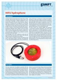
Hydrophone . ........................................................... 17<br />
Test block (transparent) . .................................................. 18<br />
Test block (black) ......................................................... 18<br />
Test cylinder set . ........................................................ 19<br />
�������������� ........................................................... 19<br />
��������������������������������� ............................................ 20<br />
����������������������������������� ........................................ 20<br />
����������������������������� ............................................. 20<br />
����������������������� .................................................... 21<br />
������������������������ ................................................... 21<br />
Test block for angle beam probe . ............................................ 21<br />
Angle beam wedge . ...................................................... 22<br />
Crack depth test block . .................................................... 22<br />
Discontinuity test block . .................................................. 22<br />
����������������������������� ............................................... 23<br />
Acoustic impedance samples . .............................................. 23<br />
������������������������ ................................................. 23<br />
Hydrophone set. . . . . . . . . . . . . . . . . . . . . . . . . . . . . . . . . . . . . . . . . . . . . . . . . . . . . . . . . . 24<br />
������������� ........................................................... 24<br />
��������������������� .................................................... 25<br />
Lambda plates ........................................................... 25<br />
Transit time pipe ......................................................... 25<br />
Breast phantom . ........................................................ 26<br />
Eye phantom ............................................................ 26<br />
Heart model . ........................................................... 26<br />
Tripod set ............................................................... 27<br />
��������������� ......................................................... 27<br />
Adapter BNC/LEMO for GAMPT-Scan . ......................................... 27<br />
cw (continuous wave) 28-35<br />
cw generator SC500 . ......................................................28<br />
Debye-Sears set ..........................................................29<br />
Multifrequency probe . ....................................................29<br />
Laser module (red) . ......................................................30<br />
GAMPT mbH · Hallesche Straße 99F · D-06217 Merseburg · Germany · Fon: +49 - 34 61-2786910 · Fax: +49 - 34 61-278691110 · www.<strong>gampt</strong>.de
GAMPT <strong>Catalogue</strong><br />
Laser module (green) . ....................................................30<br />
Adapter BNC/LEMO for SC500 . ..............................................30<br />
�������������������� .....................................................31<br />
������������������������������ .............................................31<br />
Projection lens . .........................................................31<br />
AOM probe adjustment . ...................................................32<br />
Acoustic absorber . .......................................................32<br />
Beam splitter ............................................................33<br />
������������������� ......................................................33<br />
������������������� ......................................................33<br />
Thermoacoustic sensor . ...................................................34<br />
������������������� ......................................................34<br />
Stirrer for SC500 . ........................................................35<br />
Adapter LEMO/BNC for hydrophone . .........................................35<br />
Doppler 36-41<br />
Ultrasonic pulse Doppler FlowDop . ..........................................36<br />
Doppler prism ...........................................................37<br />
Flow measuring set . ......................................................37<br />
Standpipes ..............................................................38<br />
Centrifugal pump MultiFlow . ..............................................38<br />
���������������� .........................................................39<br />
Flexible tubes set . .......................................................39<br />
������������ ............................................................39<br />
Arm phantom . ..........................................................40<br />
������������������ .......................................................40<br />
Ultrasonic Doppler probe . .................................................41<br />
Scanning 42-44<br />
CT scanner ..............................................................42<br />
CT control unit . .........................................................43<br />
������������ .............................................................44<br />
CT sample . .............................................................44<br />
Hydrophone support. . . . . . . . . . . . . . . . . . . . . . . . . . . . . . . . . . . . . . . . . . . . . . . . . . . . . . 44<br />
Ultrasonic gel . ..........................................................45<br />
GAMPT mbH · Hallesche Straße 99F · D-06217 Merseburg · Germany · Fon: +49 - 34 61-2786910 · Fax: +49 - 34 61-278691110 · www.<strong>gampt</strong>.de<br />
13
Equipment and materials • Pulse echo method<br />
Ultrasonic echoscope GAMPT-Scan<br />
The GAMPT-Scan�������������������������������������������<br />
unit for connection to a PC or an oscilloscope. The supplied<br />
measurement software AScan (Windows XP/7) enables an<br />
���������� ������� ����������� ���� �������� ���������� �������<br />
B-scan, M-mode, spectrum analysis). The ultrasonic probes<br />
are connected by robust snap-in plugs. The probe frequency<br />
��� ����������� �������������� ��� ���� ���������� �������� ��<br />
���������������������������������������������������������<br />
ultrasonic signal can be adjusted to nearly any test object.<br />
The loss of intensity of the ultrasonic signal from deeper<br />
������������ ����� ��� ������������ ��� ��� ������������� ��<br />
����������� ��� ����� ��� ������ ��� ������ ������ ����� ����<br />
control). Parameter such as threshold, start point, wide<br />
or slope can be chosen freely. The most important signals<br />
�������������������������������������������������������������<br />
at BNC sockets.<br />
������������������������������������������������������������<br />
a wide assortment of ultrasonic probes (1 MHz, 2 MHz<br />
and 4 MHz). The spectrum of subjects ranges from the<br />
physical basics of ultrasound up to medical and industrial<br />
applications. In connection with the scanner system (order<br />
���� ������ ���� �������� ���������� ������������� ������� ���<br />
ultrasonic imaging methods can be realised. Normally USB<br />
ist used to connect the GAMPT-Scan to the PC or notebook.<br />
Technical data<br />
• Dimensions: 225 mm x 170 mm x 315 mm<br />
• Frequency: 1-5 MHz<br />
• PC connection: USB<br />
• �������������������������������������������<br />
• Transmission signal: 10-300 Volt<br />
• ������������������������ ��<br />
• Gain: 0-35 dB<br />
• TGC: 0-30 dB, threshold, wide (width), slope, start<br />
• Outputs: TGC, trigger, TGC, RF signal, A-Scan (LF)<br />
•<br />
����������������������� �������� ��<br />
14<br />
Order no. 10121<br />
GAMPT mbH · Hallesche Straße 99F · D-06217 Merseburg · Germany · Fon: +49 - 34 61-2786910 · Fax: +49 - 34 61-278691110 · www.<strong>gampt</strong>.de
Software<br />
The supplied software AScan� ��������� ���� ���������� ����<br />
��������� ����� ��� �� ���������� ���������� ���� ������� ���<br />
connected using the USB interface.<br />
After the programm initialisation the measuring system<br />
��� ������������ �������� ���� ������������� ������������ ���<br />
connected probes are recognised due to a hardware coding<br />
in the probe plug and appropriate parameters are set up.<br />
���������������������������������������������������������������<br />
���������������������������������������������������������������<br />
and displayed on the measurement screen. The current<br />
measured amplitudes are displayed as time signal and are<br />
updated permanently. One can choose whether the HF<br />
�������������������������������������������������������������<br />
���� ����� ������������ ������������� ������������� ��� �����<br />
����������������������������������������������������������<br />
measuring marks. A freeze� ��������� ��� ����� ��� ���������<br />
����� ���������� ����������� ���� ������������ ��� ��������� ���<br />
������������������������������������������������������������<br />
�����������������������������������������������������������<br />
(FFT) and the cepstral analysis, the illustration of twodimensional<br />
ultrasonic cross-sections (B-scan) or the time<br />
��������������������������������������������������������<br />
Experiments<br />
PHY01 Basics of pulse echo method (A-Scan)<br />
PHY02� ������������������������<br />
PHY03 Acoustic attenuation in solids<br />
PHY04 Acoustic attenuation in liquids<br />
PHY05� �����������������������<br />
PHY06 Frequency dependence of resolution power<br />
PHY07� ���������������������<br />
PHY08 Ultrasonic B-Scan<br />
PHY09 Ultrasonic computer tomography (CT)<br />
PHY10� �����������������������������<br />
PHY16 Mechanical scan methods<br />
PHY20 Determination of focus zone<br />
PHY21� ����������������������������������������<br />
PHY22� ��������������������������������<br />
PHY23� �������������������������������������������<br />
IND01� �����������������������������<br />
IND02� ���������������������������������������<br />
IND03� �����������������<br />
IND06 Angle beam testing<br />
IND07 Crack depth determination (TOFD)<br />
IND08 Detection of discontinuities<br />
IND09� ����������������������<br />
MED01 Ultrasonic TM-mode (echocardiography)<br />
MED02 Ultrasonic imaging at breast phantom<br />
(mammasonography)<br />
MED04 Biometry at the eye phantom<br />
Additional part<br />
�������������������������������������������GAMPT-Scan units<br />
������������������������������������<br />
Adapter parallel to USB for GAMPT-Scan 10260<br />
Equipment and materials • Pulse echo method<br />
GAMPT mbH · Hallesche Straße 99F · D-06217 Merseburg · Germany · Fon: +49 - 34 61-2786910 · Fax: +49 - 34 61-278691110 · www.<strong>gampt</strong>.de<br />
15
Equipment and materials • Pulse echo method<br />
Ultrasonic probe 1 MHz<br />
������������������������������������������������������������<br />
intensity and short sound pulses. It makes them particularly<br />
���������������������������������������������������������<br />
metal housing and are cast on the sound surface with a<br />
�����������������������������������������������������������<br />
special plug for connection to the GAMPT-Scan or with a BNC<br />
����� ���� ���������� ����� ���� ��� ������ ����� ������ ���������<br />
����� ���� ����������� ��������� ���� ��������������� ����� �����<br />
�����������������������������������������������������������<br />
materials and for the generation of Rayleigh and shear<br />
������������������������������������������������������������<br />
���������<br />
Technical data:<br />
• Frequency: 1 MHz<br />
• Dimensions: length = 70 mm, diameter = 27 mm<br />
• Cable length: about 1 m<br />
• Sound adaptation to water/acrylic<br />
• �������������������������������������������������������<br />
GAMPT-Scan����������������������������������<br />
Experiments<br />
PHY01 Basics of pulse echo method (A-Scan)<br />
PHY02 ������������������������<br />
PHY03 Acoustic attenuation in solids<br />
PHY06 Frequency dependence of resolution power<br />
PHY07 ���������������������<br />
Ultrasonic probe 2 MHz<br />
At a frequency of 2 MHz, these probes are suitable for a wide<br />
������������������������������������������������������������<br />
axial and lateral resolution is clearly higher than that of 1<br />
MHz probes. On the other hand the attenuation of 2 MHz<br />
sound in most materials is not yet too large, so areas under<br />
����������������������������������������������������������<br />
��������������������������������������������������������������<br />
objects and as ultrasound Doppler probes.<br />
Technical data:<br />
• Frequency: 2 MHz<br />
• Dimensions: length = 70 mm, diameter = 27 mm<br />
• Cable length: about 1 m<br />
• Sound adaptation to water/acrylic<br />
�������������������������������������������������������<br />
GAMPT-Scan����������������������������������<br />
16<br />
Order no. 10131<br />
Order no. 10141 (BNC)<br />
• Order no. 10132<br />
Experiments<br />
PHY02 ������������������������<br />
PHY03 Acoustic attenuation in solids<br />
PHY04 Acoustic attenuation in liquids<br />
PHY05 �����������������������<br />
PHY08 Ultrasonic B-Scan<br />
PHY09 Ultrasonic computer tomography (CT)<br />
PHY10 �����������������������������<br />
PHY13 ������������������������<br />
PHY15 Fluid mechanics<br />
PHY16 Mechanical scan methods<br />
PHY20 Determination of focus zone<br />
PHY08 Ultrasonic B-Scan<br />
PHY16 Mechanical scan methods<br />
PHY20 Determination of focus zone<br />
PHY22 ��������������������������������<br />
PHY23 �������������������������������������������<br />
IND02 ���������������������������������������<br />
MED02 Ultrasonic imaging at breast phantom<br />
(mammasonography)<br />
Order no. 10142 (BNC)<br />
PHY21 ����������������������������������������<br />
PHY22 ��������������������������������<br />
PHY23 �������������������������������������������<br />
IND01 �����������������������������<br />
IND03 �����������������<br />
IND05 �����������������������<br />
IND06 Angle beam testing<br />
IND07 Crack depth determination (TOFD)<br />
IND08 Detection of discontinuities<br />
IND09 ����������������������<br />
GAMPT mbH · Hallesche Straße 99F · D-06217 Merseburg · Germany · Fon: +49 - 34 61-2786910 · Fax: +49 - 34 61-278691110 · www.<strong>gampt</strong>.de
Ultrasonic probe 4 MHz<br />
The 4 MHz probes are distinguished by an extreme short<br />
�����������������������������������������������������������<br />
�������������������������������������������������������������<br />
structures.<br />
Technical data<br />
• Frequency: 4 MHz<br />
• Dimensions: length = 70 mm, diameter = 27 mm<br />
• Cable length: about 1 m<br />
• Sound adaptation to water/acrylic<br />
• �������������������������������������������������������<br />
GAMPT-Scan����������������������������������<br />
Experiments<br />
PHY03 Acoustic attenuation in solids<br />
PHY06 Frequency dependence of resolution power<br />
MED01 Ultrasonic TM-mode (echocardiography)<br />
Hydrophone<br />
���� ����������� ���� ��� ����� ��� �������� ���� ������ ����<br />
characteristic of an ultrasonic probe. The amplitude<br />
modulation along the central axis of a sound probe can<br />
��� ����� ��� ���������� ���� ����� ����� ������� ������� ������<br />
����������� ���� ������ ���������� ��� ���� ������ ����� ���� ��<br />
��������������������� ���������� ����� ���� ������ ��������<br />
The hydrophone is suitable for a frequency range from 1 to<br />
� �������������������������������������������������������<br />
of the GAMPT-Scan. In the simplest case, measurements<br />
�������������������������������������������������������<br />
using the CT scanner. A suitable holder for the hydrophone<br />
������������������������������������<br />
Technical data<br />
• Frequency range: 1-5 MHz<br />
• Dimensions: length = 125 mm, width = 24 mm<br />
• �������������������������������� ��<br />
• Cable length: about 1 m<br />
Experiments<br />
PHY10 �����������������������������<br />
PHY19 ������������������������<br />
PHY20 Determination of focus zone<br />
PHY23 �������������������������������������������<br />
Order no. 10134<br />
Order no. 10144 (BNC)<br />
Order no. 10250<br />
Equipment and materials • Pulse echo method<br />
GAMPT mbH · Hallesche Straße 99F · D-06217 Merseburg · Germany · Fon: +49 - 34 61-2786910 · Fax: +49 - 34 61-278691110 · www.<strong>gampt</strong>.de<br />
17
Equipment and materials • Pulse echo method<br />
Test block (transparent)<br />
The transparent test block of homogeneous acrylic is<br />
����������� ��������� ���� ����������� ���������������� �������<br />
is a material with medium acoustic damping, therefore<br />
���� ������������ ������ ��� ���������� ���� ���� �������� ���<br />
������������������������������������������������������������<br />
depths, a large defect (acoustic shadow) and a double<br />
defect (resolution power). This allows basic knowledge to<br />
����������������������������������������������������������<br />
�������������������������������������������������������<br />
�����������������������������������������������������������<br />
frequencies.<br />
Technical data<br />
• Dimensions: 150 mm x 80 mm x 40 mm<br />
• Material: acrylic, transparent<br />
• ��������������������� ������������������<br />
• Density: 1.2 g/cm³<br />
Defects: 11<br />
• Order no. 10201<br />
Experiments<br />
PHY01 Basics of pulse echo method (A-Scan)<br />
PHY06 Frequency dependence of resolution power<br />
PHY08 Ultrasonic B-Scan<br />
PHY16 Mechanical scan methods<br />
IND01 �����������������������������<br />
Test block (black)<br />
This test block of black, opaque acrylic is intended for an<br />
���������������������������������������������������������<br />
focuses on searching for defects in unknown test objects.<br />
The test block can be scanned from all sides and the number<br />
and position of defects determined. In further experiments,<br />
��������������������������������������������������������<br />
����������������������������������������������������������<br />
����������������������������������������������������������<br />
strategies for the complete localisation of all defects. All<br />
experiments, for which the transparent test block is required<br />
can also be carried out with the black test block. The acoustic<br />
properties and arrangement of defects correspond to those<br />
of the transparent test block.<br />
Technical data<br />
• Dimensions: 150 mm x 80 mm x 40 mm<br />
• Material: acrylic, black<br />
• ��������������������� ������������������<br />
• Density: 1.2 g/cm³<br />
• Defects: 11<br />
Experiments<br />
PHY01 Basics of pulse echo method (A-Scan)<br />
PHY06 Frequency dependence of resolution power<br />
PHY08 Ultrasonic B-Scan<br />
PHY16 Mechanical scan methods<br />
IND01 �����������������������������<br />
18<br />
Order no. 10204<br />
GAMPT mbH · Hallesche Straße 99F · D-06217 Merseburg · Germany · Fon: +49 - 34 61-2786910 · Fax: +49 - 34 61-278691110 · www.<strong>gampt</strong>.de
Test cylinder set<br />
������ ���������� ��������� ���������� ���� �����������<br />
���� �������� ��������� �������� ����������� ������ ���� ��<br />
����������������������������������������������������������<br />
�������������������������������������������������������������<br />
���� ������ �������� ��� ��������� ������� ���� ����� ��������<br />
allows a detailed discussion of error. The determination<br />
��� ���� ��������� ������������ ��� ������������� ��� ��������<br />
ultrasound frequencies teaches the basic relations of<br />
ultrasonic absorption in solids.<br />
Technical data<br />
• Dimensions: diameter = 40 mm, length = 40 mm, 80 mm<br />
and 120 mm<br />
• Material: acrylic, transparent<br />
• ��������������������� ������������������<br />
• Density: 1.2 g/cm³<br />
Experiments<br />
PHY02 ������������������������<br />
PHY03 Acoustic attenuation in solids<br />
PHY22 ��������������������������������<br />
Shear wave set<br />
�����������������������������������������������������������<br />
������������������������������������������������������������<br />
������ ����� �� ��������� ��������������� ����� ������������<br />
������� ����� ����� ������������� ���������� ���� ����������<br />
����� ������������� ��� ������ ������ ���� ��� ��������� ��� ��<br />
angle-dependent manner. The measurement is carried<br />
���� ��� ������������� ����� ���� ������� ������� �� ������ ���<br />
������������������������������������������������������<br />
in the longitudinal direction and has an angle scale. From<br />
������������� ��� ������������� ���� ������ ������ ���������<br />
the elastic constants of the material can be determined.<br />
��������������������������������������������������������<br />
With the aluminium sample, this experimental set up is<br />
also suitable for determining the attenuation of ultrasound<br />
in liquids (water, glycerin, oil etc.) due to its adjustable<br />
sample plate.<br />
Technical data<br />
•<br />
•<br />
•<br />
•<br />
•<br />
•<br />
•<br />
Sample holder with angle scale 0-360° (5° graduation)<br />
Sample material 1: acrylic (transparent)<br />
��������������� ������������������ ����<br />
����������������� ���<br />
Sample material 2: aluminium<br />
��������������� ������������������ ����<br />
����������������� ���<br />
2 probe supports of acrylic (black)<br />
������������������<br />
Experiments<br />
PHY04 Acoustic attenuation in liquids<br />
PHY07 ���������������������<br />
Order no. 10207 (Set)<br />
Spare parts<br />
Equipment and materials • Pulse echo method<br />
3 cylinders 10203<br />
Probe support 10215<br />
Cylinder holder 10205<br />
Order no. 10218 (Set)<br />
Spare parts<br />
���������������� 10214<br />
Probe support 10215<br />
Acrylic sample 10211<br />
Aluminium sample 10213<br />
GAMPT mbH · Hallesche Straße 99F · D-06217 Merseburg · Germany · Fon: +49 - 34 61-2786910 · Fax: +49 - 34 61-278691110 · www.<strong>gampt</strong>.de<br />
19
Equipment and materials • Pulse echo method<br />
Acrylic sample<br />
for shear wave set<br />
��� ���������� �������� ��������� ���������� ���� ������������<br />
��������������������������������������������������������������<br />
�������������������������������������������������������������<br />
�������������������������������������������������������������<br />
�����������������������������������������������������������<br />
water.<br />
Technical data<br />
• Sample material: acrylic<br />
• ��������������� ������������������ ���<br />
����������������� ���<br />
Experiments<br />
PHY07 ���������������������<br />
Aluminium sample<br />
for shear wave set<br />
������������������������������������������������������������<br />
�����������������������������������������������������������<br />
����������������������������������������������������������<br />
��������� ���� ���� ������ ������ ��������� ��� ���������� ���<br />
greater than in water. The aluminium sample is also suitable<br />
����������������������������������������������������������<br />
the pulse echo method, for example for the determination<br />
of the acoustic attenuation in liquids.<br />
Technical data<br />
• Sample material: aluminium<br />
• ��������������� ������������������ ���<br />
����������������� ���<br />
Experiments<br />
PHY04 Acoustic attenuation in liquids<br />
PHY07 ���������������������<br />
POM sample<br />
for shear wave set<br />
������������������������������������������������������������<br />
�������������������������������������������������������������<br />
��� ����������������� ������ ����������� ���� ������������ ��<br />
�����������������������������������������������������������<br />
in water.<br />
Technical data<br />
• Material: POM<br />
• ��������������� ������������������ ���<br />
����������������� ���<br />
Experiments<br />
PHY07 ���������������������<br />
20<br />
Order no. 10211<br />
Order no. 10213<br />
Order no. 10212<br />
GAMPT mbH · Hallesche Straße 99F · D-06217 Merseburg · Germany · Fon: +49 - 34 61-2786910 · Fax: +49 - 34 61-278691110 · www.<strong>gampt</strong>.de
�����������������������<br />
The pair of acrylic plates allows a number of interesting<br />
�����������������������������������������������������������<br />
�����������������������������������������������������������<br />
������������������������������������������������������������<br />
shift of the spectrum to lower frequencies due to frequency<br />
���������� ������������� ���� ��������� ��� ���� ����������<br />
includes the thickness of the plate as a periodic modulation.<br />
��� �������������� ���� �������� ���� �������� �� ������� ����<br />
������������������������������������������������������<br />
���������������������������������������������������������<br />
using cepstrum analysis. The set contains an acrylic delay<br />
line.<br />
Technical data<br />
•<br />
•<br />
•<br />
•<br />
Material: acrylic, transparent<br />
Dimensions: width = 40 mm, length = 80 mm,<br />
�������������� ���������� ��<br />
��������������������� ������������������<br />
Density: 1.2 g/cm³<br />
Rayleigh wave test block<br />
������������������������������������������������������������<br />
�����������������������������������������������������������<br />
���������������������������������������������������������<br />
�������� ����� ���� �������� ��������� �������� ������ ���� ��<br />
����������������������������������������������������������<br />
in the material testing is the measurement of crack depth<br />
��� ������ ��� ��������� ������� ����������� ������ ���� �������<br />
������� ��� ��������� ������� ��� ���� ����� ������ ���� ������<br />
������������������������������������������������<br />
Technical data<br />
• Material: aluminium<br />
• Dimensions: 35 mm x 35 mm x 600 mm<br />
• Weight: 2.5 kg<br />
• ���������������������������������������� ���<br />
• ����������������������������������������������������<br />
Test block for angle beam probe<br />
The aluminium test block is used to adjust angle beam<br />
probes in terms of the angle of incidence, the sound<br />
����������������������������������������������������������<br />
line. The angle is determined by measuring the wall echos<br />
��� ��������� ����������� ����������� ���� ����������� ������ ��<br />
carried out on a cylindrical discontinuity (drill hole).<br />
Technical data<br />
•<br />
•<br />
•<br />
•<br />
Material: aluminium<br />
��������������� ������������������ ����<br />
����������������� ���<br />
Dimensions: 35 mm x 35 mm x 120 mm<br />
Drill hole: diameter = 8 mm<br />
Order no. 10202<br />
Experiments<br />
PHY05 �����������������������<br />
Order no. 10232<br />
Equipment and materials • Pulse echo method<br />
Experiments<br />
IND02 ���������������������������������������<br />
Order no. 10240<br />
Experiments<br />
IND06 Angle beam testing<br />
GAMPT mbH · Hallesche Straße 99F · D-06217 Merseburg · Germany · Fon: +49 - 34 61-2786910 · Fax: +49 - 34 61-278691110 · www.<strong>gampt</strong>.de<br />
21
Equipment and materials • Pulse echo method<br />
Angle beam wedge<br />
���� ��� ���� ����� ���������� �������� ��� ���������������<br />
testing by ultrasound is the angle beam testing. The<br />
���������������������������������������������������������<br />
results in accordance with the law of refraction from the<br />
��������������������������������������������������������<br />
���� ��������� ������ ��������������� ���� ������ ����� �����<br />
������������������������������������������������������������<br />
�����������������������������������������������������������<br />
probe). The angle beam wedges can be used with all GAMPT<br />
probes (1, 2 and 4 MHz).<br />
Technical data<br />
• Material: acrylic<br />
• �������������������������������� ������������������<br />
• Angle of incidence (delay line):<br />
• Resulting angle in aluminium<br />
17° 38° 56°<br />
������������������ ����� ��� ��� ���<br />
������������������������� ����� ���<br />
Crack depth test block<br />
���� ����� ������ ��������� ������� ��� ��������� �������� ���<br />
���������������������������������������������������������<br />
cracks and determine their depth. An angle beam probe is<br />
used to determine the angle echo amplitude depending on<br />
the depth of cracks. At greater crack depths this method<br />
������������������������������������������������������<br />
cracks at greater depth as well. The performance and limits<br />
of both methods are determined with this test block.<br />
Technical data<br />
•<br />
•<br />
•<br />
•<br />
22<br />
Material: aluminium<br />
��������������� ������������������ ����<br />
����������������� ���<br />
Dimensions: 35 mm x 35 mm x 300 mm<br />
Crack depths: 2, 4, 6, 8, 10 and 15 mm<br />
Discontinuity test block<br />
���� ���������� ����� ������ ��������� ��������� ������ ���<br />
���������� ������ ���� ����� ���� ���� ����������� ��� �������<br />
����� ������������ ���������� ���� �� ����������� ��������� ���<br />
��������������� ���� ������������ ���������� ���� �� ���������� �<br />
�������������������������������������������������������������<br />
����������� ��� ���� ��������� ����������� ������� ���� ��<br />
examined at the crack. For the detection of discontinuities<br />
�����������������������������������������������������������<br />
as echo-method, delta-method, tandem-method, transfermethod<br />
and angle-method.<br />
Technical data<br />
• Material: aluminium<br />
• ��������������� ������������������ ����<br />
����������������� ���<br />
• Dimensions: 35 mm x 35 mm x 300 mm<br />
Order no. 10233 (17°)<br />
Order no. 10234 (38°)<br />
Order no. 10235 (56°)<br />
Experiments<br />
IND06 Angle beam testing<br />
IND07 Crack depth determination (TOFD)<br />
IND08 Detection of discontinuities<br />
Order no. 10241<br />
Experiments<br />
IND07 Crack depth determination (TOFD)<br />
Order no. 10242<br />
•<br />
Number of discontinuities: 6<br />
Experiments<br />
IND08 Detection of discontinuities<br />
GAMPT mbH · Hallesche Straße 99F · D-06217 Merseburg · Germany · Fon: +49 - 34 61-2786910 · Fax: +49 - 34 61-278691110 · www.<strong>gampt</strong>.de
Transceiver delay line (TOFD)<br />
For the inspection of discontinuities according to the TOFD<br />
�����������������������������������������������������������<br />
����� ��������� ��� �� ������������ ������ ���� �� ��������� �����<br />
������ ���� ������� ����� ���� �������� ������� ����� ������� ��� �<br />
�����������������������������������������������������������<br />
����� ��� ������������� ���������� ������ ����� ���� ���� �����<br />
probes of the same frequency, it is simple to assemble such<br />
a TR probe.<br />
Technical data<br />
• Material: acrylic<br />
• ������������������������������� ���<br />
• Angle of incidence: 38°<br />
• ����������������������������������������������<br />
��������� ����� ���<br />
Acoustic impedance samples<br />
��������������������������������������������������������<br />
�����������������������������������������������������������<br />
��� ���������� ��� ��������� ��������� ����������� ����� ��������<br />
���� ������ ���� ���������� ��� ������� ����������� ������������<br />
����������������������������������������������������������<br />
���� ����������� ���� ��� ����� ��� ���������� ���� ����������<br />
��������������������������������������������������������<br />
Technical data<br />
•<br />
•<br />
�����������������������������������������<br />
(height = 20 mm, diameter = 38 mm)<br />
Material combinations: acrylic/PVC, acrylic/brass and<br />
PVC/brass (height = 40 mm, diameter = 38 mm)<br />
Experiments<br />
PHY21 ����������������������������������������<br />
PHY22 ��������������������������������<br />
Rayleigh wave attachment<br />
����� ����� ������������ ��� ��� ��������� ��� ������� ���� �������<br />
�������� ������ ���������� ������� ��� �� ����� ������� ������� ���<br />
aluminium). This can be used to determine the sound<br />
�����������������������������������������������������������<br />
material faults near the surface. The attachment has a<br />
directionally dependent design in order to optimise signal<br />
amplitude and is especially adapted to a 1 MHz probe.<br />
Technical data<br />
• Material: acrylic<br />
• Required excitation frequency (probe): 1 MHz<br />
• Diameter: 32 mm<br />
• Height: 10 mm<br />
Experiments<br />
IND02 ���������������������������������������<br />
Order no. 10237<br />
Experiments<br />
IND07 Crack depth determination (TOFD)<br />
IND08 Detection of discontinuities<br />
Order no. 10208<br />
Order no. 10231<br />
Equipment and materials • Pulse echo method<br />
GAMPT mbH · Hallesche Straße 99F · D-06217 Merseburg · Germany · Fon: +49 - 34 61-2786910 · Fax: +49 - 34 61-278691110 · www.<strong>gampt</strong>.de<br />
23
Equipment and materials • Pulse echo method<br />
Hydrophone set<br />
���������������������������������������������������������<br />
examine ultrasonic propagation phenomena and sound<br />
������� ��� ��������� �� ����������� ����� ��� �������� �����<br />
���������������������������������������������������������<br />
a lateral resolution of about 3 mm. To determine the focus<br />
zone of an ultrasonic probe, the set contains a small sample<br />
��������������������������������������������������������<br />
���������������������������������������������������������<br />
�������������� ����������� ��� ��������� ���������������<br />
focus zone of the probe. At the same time, this arrangement<br />
��� ����� ��������� ���� ������������ ���� ������ ��������� ���<br />
���� ������ ��������� ����� ���� ��� ���������� ������ � ������<br />
no.20100). A part of the hydrophone holder is directly<br />
adaptable to the sample holder of the CT scanner (order<br />
no. 60100). This allows also the use of the hydrophone to to<br />
�����������������������������������������������������������<br />
at high resolution.<br />
Technical data (hydrophone)<br />
• Frequency range: 1-5 MHz<br />
• Dimensions: length = 125 mm, width = 24 mm<br />
• �������������������������������� ��<br />
• Cable length: about 1 m<br />
Experiments<br />
PHY10 �����������������������������<br />
PHY19 ������������������������<br />
PHY20 Determination of focus zone<br />
Lamb wave set<br />
This set permits the measurement of the frequency<br />
���������� ������������ ��������� ������������� ��� ����������<br />
������ ��� �� ����� ������ ������ ������ �������� ������ ��������<br />
������ ������������� ����� ������ ��� ��������� �����������<br />
are excited in thin glass plates. To determine the sound<br />
��������� ������ ������ ��� ����� �������������� ������ �����<br />
are decoupled in water and recorded with a hydrophone<br />
(order no. 10250). This measurement setup allows the<br />
�������������� ��� ���� ������ ���� ������ ��������� ��� ���<br />
��������������������������������������������������������<br />
�����������������������������������<br />
Technical data<br />
•<br />
•<br />
24<br />
�������������������������������������������������<br />
attachment with comb structure, thin plate of glass<br />
Special lift table arrangement with probe support<br />
�������������������<br />
Experiments<br />
PHY23 �������������������������������������������<br />
Order no. 10251 (Set)<br />
Spare parts<br />
���������������� 10214<br />
Probe support 10215<br />
Hydrophone 10250<br />
Hydrophone support plate 10252<br />
Hydrophone support 60123<br />
Order no. 10300<br />
Spare parts<br />
Tripod set<br />
10301<br />
10310<br />
Lift table set with probe support 10320<br />
��������������������� 10308<br />
GAMPT mbH · Hallesche Straße 99F · D-06217 Merseburg · Germany · Fon: +49 - 34 61-2786910 · Fax: +49 - 34 61-278691110 · www.<strong>gampt</strong>.de
Lamb wave delay lines<br />
���������������������������������������������������������<br />
��� �� ����� ����� ������� ������ ����� ����������� ��� ��������<br />
������������ ����� ������ ��� ��������� ������������ ���� ��<br />
excited. This makes it possible to measure the frequency<br />
���������� ������������ ��������� ������������� ��� ����������<br />
������ ��� �� ����� ������ ������� ��� ���������� ������ ��������<br />
������ ����� ��� ������ �������������� ������ ������ ���<br />
decoupled in water and recorded with a hydrophone (order<br />
no. 10250).<br />
Technical data<br />
•<br />
����������������������������������<br />
acrylic - probe attachment with comb structure,<br />
glass - thin plate<br />
Experiments<br />
PHY23 �������������������������������������������<br />
Lambda plates<br />
������ ������ ���� ���������� ��� ��������� ��������� ��<br />
���� ��������� �������� ���� ���������� ����� ��������<br />
��������������� ��������� ���������� �������� ���� ���������<br />
���������������������������������������������������������<br />
��������������������������������������������������������<br />
������� ���� ��� ���������� ��� ���� ��������� ��� ������������<br />
������������� ������������� ������������ ������� ������ ������<br />
passage through thin layers whose thickness falls within<br />
����������������������������������������������������������<br />
������ ������������ ������ ������� ���� ��� ��������� ����� ����<br />
plate set.<br />
Technical data<br />
• Material: aluminium,<br />
• ��������������� ������������������ ���<br />
• ����������������������������������������������� ����<br />
Experiments<br />
PHY22 ��������������������������������<br />
Transit time pipe<br />
��������������������������������������������������������<br />
measurements using the transit time method. It consists<br />
��� �� �������� ���� ����� ���� ���� ����������� ������� ����<br />
connections for the measurement circulation and holders<br />
for the ultrasonic probes.<br />
Technical data<br />
• Material: acrylic<br />
• Dimensions: 50 mm x 55 mm x 310 mm<br />
• ����������������������������������� ��<br />
• Connectors: 3/8“<br />
Experiments<br />
IND09 ����������������������<br />
Order no. 10308<br />
Order no. 10209<br />
Order no. 10180<br />
Equipment and materials • Pulse echo method<br />
GAMPT mbH · Hallesche Straße 99F · D-06217 Merseburg · Germany · Fon: +49 - 34 61-2786910 · Fax: +49 - 34 61-278691110 · www.<strong>gampt</strong>.de<br />
25
Equipment and materials • Pulse echo method<br />
Breast phantom<br />
The breast phantom silicone rubber has two inclusions. These<br />
simulate benign tumours. The position of the tumours can<br />
initially be palpated in order to carry out a targeted ultrasonic<br />
examination. By a hand guided B-scan (compound scan)<br />
����������������������������������������������������������<br />
coupling and local assignment) the tumours can be shown<br />
clearly. Position and size of the tumours can be determined<br />
�����������������������������������������������������������<br />
a practical example in the ultrasound training of physicians.<br />
Technical data<br />
• Material: silicone<br />
• ����������������������������������������� ���������<br />
diameter about 20 mm<br />
Experiments<br />
MED02 Ultrasonic imaging at breast phantom<br />
(mammasonography)<br />
Eye phantom<br />
Biometric measurements with ultrasound are an important<br />
diagnostic method in ophthalmology. The typical biometric<br />
measurements of the length of the axis of the eye are<br />
excellent for demonstrating the basics of ultrasonic pulse<br />
����� �������������� ����� ������ ���� ���� ����������� ������<br />
GAMPT-Scan (order no. 10121) with a 2 MHz probe can<br />
�������� ��������������� ������� ����� ���� ���� ��������� ����<br />
����������������������������������������������������������<br />
The geometrical dimensions of these objects can be<br />
determined by the distances of the echoes. A lesion near<br />
��������������������������������������������������������<br />
be detected.<br />
Technical data<br />
• ���������������������������������������������������������<br />
• Diameter: 80 mm<br />
Heart model<br />
������������������������������������������������������������<br />
mode (time motion mode) is used. This continuously records<br />
�����������������������������������������������������������<br />
�����������������������������������������������������������������<br />
������ �������� ��������� �� �������� ��������� ������ ����<br />
������������������������������������������������������������<br />
and heart walls. The membrane is bent upwards periodically<br />
���������������������������������������������������������������<br />
��������������������������������������������������������������<br />
��������������������������������������������������������<br />
Technical data<br />
• Double container with rubber membrane<br />
• Pressure ball of rubber<br />
Experiments<br />
MED01 Ultrasonic TM-mode (echocardiography)<br />
26<br />
Order no. 10221<br />
Order no. 10222<br />
Experiments<br />
MED04 Biometry at the eye phantom<br />
Order no. 10220<br />
GAMPT mbH · Hallesche Straße 99F · D-06217 Merseburg · Germany · Fon: +49 - 34 61-2786910 · Fax: +49 - 34 61-278691110 · www.<strong>gampt</strong>.de
Tripod set<br />
���� ������� ���� ���� ����� ������������ ��������� ���� ���<br />
together for the experiments in this catalogue. It consists of<br />
�������������������������������������������������������� ��<br />
����� �������������� ���������� ������� ���� �������� ���������<br />
���������������������������������������������������������<br />
��������������������������������������������������������<br />
to 80 mm. So all holders can be realised, which are needed<br />
for the experiments.<br />
Technical data<br />
• 1 base plate of steel, powder-coated, 25 cm x 16 cm<br />
• ������������������������������������������� ��<br />
• 2 bossheads of steel, powder-coated, Allen head screws<br />
�������������������������������� ��������������� ��<br />
• Order no. 10310<br />
Experiments<br />
IND03 �����������������<br />
PHY23 �������������������������������������������<br />
PHY24 Thermoacoustic sensor<br />
���������������<br />
���� ����������� ����� ��� ������������� ������ ��� ��������� ����<br />
������������ ����� ������ ������������� ���� ������ �������<br />
permits good coupling of the ultrasonic sensor to the<br />
�����������������������������������������������������������<br />
with a simple laboratory clamp. At a total height of 280 mm,<br />
�� ���������� ������� ��� ��������� ���� ����������� ���� ���<br />
�����������������������������������������������������������<br />
��������������������������<br />
Technical data<br />
• Material: borosilicate glass<br />
• Capacity: 2000 ml (500 ml graduation )<br />
• Height: 280 mm<br />
Diameter: 166 mm<br />
Spare parts<br />
• Order no. 10330<br />
Experiments<br />
IND03 �����������������<br />
Adapter BNC/LEMO<br />
for GAMPT-Scan<br />
The adapter permits the connection of ultrasonic probes<br />
with a BNC plug connection to the LEMO connectors of the<br />
GAMPT-Scan echoscope.<br />
Caution: GAMPT Scan and GAMPT probes are adapted<br />
������������ ��� ���� ��������� ������� ������ ������� ��� ������<br />
��������������� ������� ����� ����� ����� ���� ���������<br />
��������������������������<br />
Equipment and materials • Pulse echo method<br />
Clamp<br />
10304<br />
10305<br />
Bosshead 10303<br />
Order no. 10270<br />
GAMPT mbH · Hallesche Straße 99F · D-06217 Merseburg · Germany · Fon: +49 - 34 61-2786910 · Fax: +49 - 34 61-278691110 · www.<strong>gampt</strong>.de<br />
27
Equipment and materials • cw (continuous wave)<br />
cw generator SC500<br />
The cw generator SC500 enables the generation of<br />
����������� ������ ������ ����������� ����� �� ���� ����� ����<br />
������ ����� �� ����� ���������� ������ ��� ��� ��� ����� ���<br />
transmission frequency can be changed digitally in steps of<br />
1 Hz and is shown on a display. The sound power can also be<br />
�������������������������������������������������������������<br />
��������������������������������������������������������<br />
The transmission mode is indicated by a control lamp. An<br />
����������������������������������������������������������<br />
������� ������ ��� �� ����� ������� ���������� ����� �� �������<br />
amplitude of 50 V. The transmission frequency is also<br />
������������������������������������������<br />
To control laser diodes (red/green) in the Debye-Sears<br />
����������� ��� ���� �������� ����������� ��� ��������� ������<br />
�������������������������������������������������������������<br />
������������������������������������������������������������<br />
The cw generator SC500 is designed especially for connection<br />
��������������������������������������������������������<br />
can be generated in a range from 1–13 MHz.<br />
Technical data<br />
•<br />
•<br />
•<br />
•<br />
•<br />
•<br />
•<br />
•<br />
•<br />
•<br />
28<br />
��������������� ���<br />
Frequency resolution: 1 Hz<br />
Signal amplitude: 2-50 V<br />
��������������������������������������������������<br />
switch, status LED<br />
��������������� ���������������������<br />
Sine output: ± 5 V<br />
�������������������������������������������������������<br />
status LED<br />
����������������������������������������������<br />
Dimensions: 255 mm x 170 mm x 255 mm<br />
����������������������� �������� ��<br />
Experiments<br />
PHY11 �����������������<br />
PHY12 ����������������������������<br />
PHY17 ��������������������������������������������<br />
PHY18 ����������������������������������������������<br />
PHY19 ������������������������<br />
PHY24 Thermoacoustic sensor<br />
IND04 Concentration measurement with resonance cell<br />
Order no. 20100<br />
GAMPT mbH · Hallesche Straße 99F · D-06217 Merseburg · Germany · Fon: +49 - 34 61-2786910 · Fax: +49 - 34 61-278691110 · www.<strong>gampt</strong>.de
Debye-Sears set<br />
���� ����������� ��� ��������� ������ ���� ���� �����������<br />
������������������������������������������������������������<br />
���������������������������������������������������������<br />
that can be used for the precision adjustment of the<br />
�����������������������������������������������������������<br />
����� �� ������ �������� ��������� ����������� ��� ���� ������ ����<br />
with a lens holder that enables an exact positioning of<br />
���� ������ ����� ��� ���� ������ ����� ���� ���� ���������� ��� �<br />
����������������������������������������������������������<br />
projection).<br />
Technical data<br />
•<br />
•<br />
•<br />
•<br />
�����������������������������������������������<br />
lens holder, 105 mm x 125 mm x 100 mm<br />
Probe adjustment: POM, three-point adjustment,<br />
105 mm x 125 mm x 50 mm<br />
Ultrasonic probe: 1-13 MHz, metal housing,<br />
��������������<br />
���������������������� ��<br />
Experiments<br />
PHY11 �����������������<br />
PHY12 ����������������������������<br />
PHY17 ��������������������������������������������<br />
PHY18 ����������������������������������������������<br />
IND04 Concentration measurement with resonance cell<br />
Multifrequency probe<br />
This ultrasonic probe is designed especially for the use<br />
with the multifrequency cw generator. It is characterised<br />
��� ����� ����� ������ ����������� ����������� ��� �� ���������<br />
������������������������������������������������������������<br />
�������������������������������������������������������<br />
range can be done with only one ultrasonic probe. Like all<br />
GAMPT probes it has a robust metal housing. The sound<br />
emission surface is cast and waterproof.<br />
Technical data<br />
• Frequency: 1-13 MHz<br />
• Dimensions: 65 mmx27mm<br />
• Cable length: about 1 m<br />
Experiments<br />
PHY11 �����������������<br />
PHY12 ����������������������������<br />
PHY17 ��������������������������������������������<br />
PHY18 ����������������������������������������������<br />
PHY19 ������������������������<br />
PHY24 Thermoacoustic sensor<br />
IND04 Concentration measurement with resonance cell<br />
Order no. 20200 (Set)<br />
Spare parts<br />
Order no. <strong>2013</strong>8<br />
Equipment and materials • cw (continuous wave)<br />
Multifrequency probe <strong>2013</strong>8<br />
Laser module (red) 20210<br />
AOM probe adjustment 20224<br />
�������������������� 20225<br />
GAMPT mbH · Hallesche Straße 99F · D-06217 Merseburg · Germany · Fon: +49 - 34 61-2786910 · Fax: +49 - 34 61-278691110 · www.<strong>gampt</strong>.de<br />
29
Equipment and materials • cw (continuous wave)<br />
Laser module (red)<br />
��������������������������������������������������� ������<br />
a special housing for easy positioning in the laser support<br />
����������������������������������������������������������<br />
��� ���� ��� ���������� ���� ��� ���������� ���� ����� ���������<br />
����������������������������������������������<br />
Technical data<br />
• ��������������� ��<br />
• Power: < 5 mW<br />
• Dimensions: length = 90 mm, diameter = 17 mm<br />
• ����������� ����<br />
• Current consumption: max. 30 mA<br />
• Laser class: 3R (EN 60825-1)<br />
Experiments<br />
PHY11 �����������������<br />
PHY12 ����������������������������<br />
PHY17 ��������������������������������������������<br />
PHY18 ����������������������������������������������<br />
IND04 Concentration measurement with resonance cell<br />
Laser module (green)<br />
����������������������������������������������������������<br />
a special housing for easy positioning in the laser support of<br />
������������������������������������������������������������<br />
������������������������������������������������������������<br />
����������������������������������������������������<br />
Technical data<br />
• ���������������� ��<br />
• Power: < 5 mW<br />
• Dimensions: length = 90 mm, diameter = 17 mm<br />
• ����������� ����<br />
• Current consumption: max. 250 mA<br />
• Laser class: 3R (EN 60825-1)<br />
Experiments<br />
PHY11 �����������������<br />
PHY12 ����������������������������<br />
Adapter BNC/LEMO for SC500<br />
The adapter permits the connection of ultrasonic probes<br />
with a BNC plug connection to the LEMO sockets of the cw<br />
generator SC500.<br />
Caution: ������ ���� ������ ������� ���� ��������� ���� ���<br />
�����������������������������������������������������������<br />
�������������������������������������������������������<br />
30<br />
Order no. 20210<br />
Order no. 20211<br />
Order no. 20280<br />
GAMPT mbH · Hallesche Straße 99F · D-06217 Merseburg · Germany · Fon: +49 - 34 61-2786910 · Fax: +49 - 34 61-278691110 · www.<strong>gampt</strong>.de
AOM sample reservoir<br />
������������������������������������������������������������<br />
easy to clean and has with the plane base and walls optimal<br />
����������������������������������������������������������<br />
������������������������������������������������������������<br />
an orthogonal direction to the walls, so only the ultrasonic<br />
probe has to be adjusted. Additionally inside the laser<br />
support is a slot to input a lens holder. The lens is used to<br />
��������� �� ���������� ������ ������ ���� ���� ������������ ���<br />
�������������������������������������������������������������<br />
trays is recommended so that measurements can be carried<br />
out in rapid succession simply by replacing the sample<br />
���������������������������������������������������������<br />
costly probe adjustment (order no. 20224) just has to be<br />
purchased once.<br />
Technical data<br />
• Material: glass (wall thickness 4 mm)<br />
• Dimensions: 120 mm x 110 mm x 140 mm<br />
Experiments<br />
PHY11 �����������������<br />
PHY12 ����������������������������<br />
Cover for AOM sample reservoir<br />
��� ����� ����� ���� ������� ���������� ��� ������ ����� �����<br />
��������������������������������������������������������<br />
������������������������������������������������������������<br />
Technical data<br />
• Material: POM<br />
• Dimensions: 120 mm x 25 mm x 105 mm<br />
Experiments<br />
PHY11 �����������������<br />
Projection lens<br />
���� �������������� �������� ����� ��� ������� ��� ���� ����<br />
����� �������� ���� ������ ������� ���� ���� ����������� ����<br />
�����������������������������������������������������������<br />
�����������������������������������������������������������<br />
to a rectangular glass holder that can be inserted into<br />
the corresponding slot in the laser holder at the sample<br />
�������������������������������������������������������������<br />
����������������������������������������������������������<br />
experiments.<br />
Technical data<br />
• Dimensions of glass holder: 25 mm x 75 mm<br />
• Lens diameter: 16 mm<br />
• Focal distance of lens: 100 mm<br />
Experiments<br />
PHY12 ����������������������������<br />
Order no. 20225<br />
Order no. 20223<br />
Equipment and materials • cw (continuous wave)<br />
PHY17 ��������������������������������������������<br />
PHY18 ����������������������������������������������<br />
IND04 Concentration measurement with resonance cell<br />
Order no. 20230<br />
GAMPT mbH · Hallesche Straße 99F · D-06217 Merseburg · Germany · Fon: +49 - 34 61-2786910 · Fax: +49 - 34 61-278691110 · www.<strong>gampt</strong>.de<br />
31
Equipment and materials • cw (continuous wave)<br />
AOM probe adjustment<br />
������������������������������������������������������������<br />
consists of a probe holder for the recording of the multi<br />
��������������������������������������������������������<br />
����� �� ������� ���� �������� �������� ������ ������� ���� ��<br />
adjusted with three screws so that the probe and the sound<br />
����������������������������������������������������������<br />
���������������������������������������������������������<br />
�����������������������������������������������������������<br />
���������������������������������������������������������<br />
pattern and sharp images of the central projection.<br />
Technical data<br />
• Material: POM<br />
• Dimensions: 120 mm x 50 mm x 105 mm<br />
• Three-point adjustment with probe support<br />
Experiments<br />
PHY11 �����������������<br />
PHY12 ����������������������������<br />
PHY17 ��������������������������������������������<br />
PHY18 ����������������������������������������������<br />
IND04 Concentration measurement with resonance cell<br />
Acoustic absorber<br />
The acoustic absorber consists of a special silicone material<br />
����� ��� �������� ��� ���������� ����������� ������ ������<br />
���������������������������������������������������������<br />
��������������������������������������������������������<br />
sensor. The acoustic impedance of the silicone material is<br />
������������������������������������������������������������<br />
the surface of the absorber. The sound energy absorbed is<br />
������������������������������������������������������������<br />
of the material. (The colour of the supplied acoustic absorber<br />
�������������������������������������������������<br />
Technical data<br />
• Material: silicone<br />
Dimensions: 90 mm x 110 mm x 19 mm<br />
Experiments<br />
PHY12 ����������������������������<br />
PHY18 ����������������������������������������������<br />
PHY24 Thermoacoustic sensor<br />
32<br />
Order no. 20224<br />
• Order no. 20227<br />
GAMPT mbH · Hallesche Straße 99F · D-06217 Merseburg · Germany · Fon: +49 - 34 61-2786910 · Fax: +49 - 34 61-278691110 · www.<strong>gampt</strong>.de
Beam splitter<br />
A semitransparent mirror is used as a beam splitter for laser<br />
��������������������������������������������������<br />
Technical data<br />
• Dimensions of the mirror: 38 mm x 25 mm<br />
• Dimensions of the support: 90 mm x 60 mm x 80 mm<br />
Experiments<br />
PHY17 ��������������������������������������������<br />
PHY18 ����������������������������������������������<br />
�������������������<br />
���� ��������� ��� ��������� ��� �� �������� ����� �����������<br />
����������������������������������������������������������<br />
in order to adjust the laser beam precisely to the target<br />
���������������������������������������������<br />
Technical data<br />
• ������������������������������ ������� ��<br />
• Dimensions of the support: 120 mm x 60 mm x 80 mm<br />
Experiments<br />
PHY17 ��������������������������������������������<br />
PHY18 ����������������������������������������������<br />
IND04 Concentration measurement with resonance cell<br />
Photodiode receiver<br />
���� ����������� ��������� ���� ����������� ��������� ����<br />
���� ������������� ���������� ��� ���� ���������� ��� ���� �����<br />
�����������������������������������������������������������<br />
be measured and the modulations that occur (AOM) are<br />
���������������������������������������������������������<br />
supplied completely with power supply and BNC connector<br />
cable.<br />
Technical data<br />
• ���������������������������������������������������������<br />
400-1100 nm<br />
• ������������������������������ ��<br />
• ����������������������� ���<br />
• Power supply: 12 V, 500 mW<br />
• ��������������������������� ������������<br />
• Dimensions: 120 mm x 60 mm x 80 mm<br />
Experiments<br />
PHY17 ��������������������������������������������<br />
PHY18 ����������������������������������������������<br />
IND04 Concentration measurement with resonance cell<br />
Order no. 20301<br />
Order no. 20302<br />
Order no. 20303<br />
Equipment and materials • cw (continuous wave)<br />
GAMPT mbH · Hallesche Straße 99F · D-06217 Merseburg · Germany · Fon: +49 - 34 61-2786910 · Fax: +49 - 34 61-278691110 · www.<strong>gampt</strong>.de<br />
33
Equipment and materials • cw (continuous wave)<br />
Thermoacoustic sensor<br />
���� ��������������� ������� ��� �� ����� �������� �������������<br />
measurement method for the determination of the local<br />
����������������������������������������������������������<br />
���� ������ ��� ����������� ��� ������ ������� ����� ����� ������<br />
������������������������������������������������������������<br />
��������������������������������������������������������������<br />
���������������������������������������������������������<br />
�����������������������������������������������������������<br />
or with the PC through a USB interface. To compensate for<br />
���� �������� ������������� ���� ������������ ��������<br />
has a zero point calibration. The set includes a connection<br />
�����������������������������������������������������������<br />
�������������������������������������������������������������<br />
local resolution, so that the intensity distribution of sound<br />
����������������������<br />
Technical data<br />
Sensor:<br />
• ���������������������� ����<br />
• ��������������������� ��� ���<br />
• ��������������������� ��� ��<br />
• ������������������������������������� ����������<br />
��� ��<br />
�������������������<br />
• Signal output: ± 10 V DC<br />
• Zero point calibration (temperature compensation)<br />
• Dimensions: 80 mm x 107 mm x 140 mm<br />
• ����������������������� �<br />
Experiments<br />
PHY24 Thermoacoustic sensor<br />
Measuring reservoir<br />
������������������������������������������������������������<br />
����������� �� �������� ��� ��������� ��� ���� ������ ����� ��� ���<br />
�������������������������������������������������������������<br />
�������������������������������������������������������������<br />
to hold an ultrasonic acoustic absorber of silicone (order<br />
no. 20227).<br />
Technical data<br />
• Material: acrylic<br />
• Dimensions: about 310 mm x 112 mm x 116 mm<br />
Experiments<br />
PHY24 Thermoacoustic sensor<br />
34<br />
Order no. 20400<br />
Spare parts<br />
Thermoacoustic probe 20410<br />
������������������ 20420<br />
�������������������� 20421<br />
Order no. 20430<br />
GAMPT mbH · Hallesche Straße 99F · D-06217 Merseburg · Germany · Fon: +49 - 34 61-2786910 · Fax: +49 - 34 61-278691110 · www.<strong>gampt</strong>.de
Stirrer for SC500<br />
We recommend the use of a stirrer for measurements with the<br />
thermoacoustic probe or the concentration measurements<br />
with the resonance cell. In case of the thermoacoustic sensor,<br />
���� �������� ��������� ���� ���������� ��� ������ �����������<br />
�������������������������������������������������������<br />
������������������������������������������������������������<br />
be plugged directly into the laser probe socket of the SC500<br />
and the speed can be controlled by the controller for the<br />
�����������������������������������������������������������<br />
stirrer.<br />
Technical data<br />
• Propeller stirrer of plastic<br />
• Speed: 0-120 rpm<br />
• Connection: plug connector for connection to laser plug<br />
socket of the SC500<br />
Experiments<br />
PHY24 Thermoacoustic sensor<br />
Adapter LEMO/BNC<br />
for hydrophone<br />
The adapter allows the connection of the GAMPT hydrophone<br />
with LEMO plug connection to the BNC connectors of an<br />
oscilloscope.<br />
Order no. 20450<br />
Order no. 20290<br />
Equipment and materials • cw (continuous wave)<br />
GAMPT mbH · Hallesche Straße 99F · D-06217 Merseburg · Germany · Fon: +49 - 34 61-2786910 · Fax: +49 - 34 61-278691110 · www.<strong>gampt</strong>.de<br />
35
Equipment and materials • Doppler<br />
Ultrasonic pulse Doppler FlowDop<br />
The pulse Doppler unit generates transmission pulses<br />
with an adjustable frequency of 1, 2 or 4 MHz transmitted<br />
����������������������������������������������������������<br />
������ ���� ��������� ��� ���������� ��� ������� ���������� ��<br />
�����������������������������������������������������������<br />
���� ��������� ��� ���������� ����������� ������ ���� ����������<br />
���� ���������� ��� ���� �������� ���� ��������� ������� ��� ����<br />
�����������������������������������������������������������<br />
is a measure of the amplitude of the registered signal and<br />
������������������������������������������������������������<br />
particles. The measured signal can be adapted to the<br />
�������������������������������������������������������<br />
transmission power and measurement depth. The measured<br />
���������������������������������������������������������<br />
on the computer using a USB interface.<br />
Technical data<br />
• Frequency: 1, 2 and 4 MHz<br />
• Gain: 10-40 dB<br />
• �����������������������������������������������������<br />
• Interface to PC: USB<br />
• Dimensions: 255 mm x 170 mm x 315 mm<br />
• ����������������������� ����� ����� ��<br />
Software<br />
Using the FlowView software included, data measured by<br />
��������������������������������������������������������<br />
connected using a USB interface. During measurement, the<br />
������������������������������������������������������������<br />
is carried out by a transformation into the frequency space<br />
using the Fourier transformation. The spectrum is used<br />
��� ���������� ���� �������� ���� �������� ���������� ������<br />
��������������������������������������������������������<br />
����������������������������������������������������������<br />
�������������������������������������������������������������<br />
also displayed.<br />
����������� ����������� ���������� ���� ���� �������� ��� ���<br />
����������������������������������������������������������<br />
36<br />
�������������������������������������������������������������<br />
�����������������������������������������������������������<br />
it is possible to obtain information from neighbouring areas<br />
��� ���� ����� �������������� ���� ����� ��������� ������� ��� ����<br />
������������������������������������������������������������<br />
����������������������������������<br />
Experiments<br />
PHY13 ������������������������<br />
PHY15 Fluid mechanics<br />
IND05 �����������������������<br />
MED03 Basics of Doppler sonography<br />
MED05 Vascular ultrasound (angiology)<br />
MED06 Peripheral Doppler blood pressure measurement<br />
Order no. 50100<br />
GAMPT mbH · Hallesche Straße 99F · D-06217 Merseburg · Germany · Fon: +49 - 34 61-2786910 · Fax: +49 - 34 61-278691110 · www.<strong>gampt</strong>.de
Doppler prism<br />
���� �������� ������ ������� ��� �� ����������� �������� ���<br />
����������� ������ ���� ���� ���� ����� ��� ������ ���� ���������<br />
�������� ��� ��� ��� ���������� ������� ���� ��������� ��� ���� ���<br />
pipe or the hose. The plane surfaces guarantee a good<br />
coupling to the ultrasonic probe. The extent of frequency<br />
shift depends primarily on the angle between the irradiating<br />
����������� ����� ���� ���� ���������� ��� ����� ���� �������<br />
����������������������������������������������������������<br />
demonstrate the dependence of the frequency shift on the<br />
Doppler angle.<br />
Technical data<br />
• Material: acrylic<br />
• Adapter for tubes/pipes: 1/2“, 3/8“ or 1/4“<br />
• Angle of incidence: 15°, 30°, 60°<br />
• Delay line: 30 mm<br />
Experiments<br />
PHY13 ������������������������<br />
PHY15 Fluid mechanics<br />
IND05 �����������������������<br />
Flow measuring set<br />
����������������������������������������������������������<br />
���� ������ ����� ������ ��������� ������ ����������� ���<br />
connectors are designed for 3/8“ tubes. Using the Doppler<br />
����������������������������������������������������������<br />
����������������������������������������������������������<br />
combined with the standpipes for pressure measurement<br />
(order no. 50150) and the centrifugal pump (order no.<br />
50130). With that a lot of interesting experiments can be<br />
������������ ��������� ��� ���� ����������� ����������������<br />
����������������������������������������������������������<br />
���� ����� ����������� ������� ��� ���������� �� ���� �������<br />
(including luer lock connectors).<br />
Technical data<br />
• Material: acrylic<br />
• Pipe length: 300 mm<br />
• ������������������������� ������� ������ ��<br />
• Connections: 3/8“<br />
Experiments<br />
PHY13 ������������������������<br />
PHY15 Fluid mechanics<br />
IND05 �����������������������<br />
Order no. 50111 (1/2“)<br />
Order no. 50112 (3/8“)<br />
Order no. 50113 (1/4“)<br />
Order no. 50201 (Set)<br />
Spare parts<br />
GAMPT mbH · Hallesche Straße 99F · D-06217 Merseburg · Germany · Fon: +49 - 34 61-2786910 · Fax: +49 - 34 61-278691110 · www.<strong>gampt</strong>.de<br />
Equipment and materials • Doppler<br />
Doppler prisms 50111, 50112, 50113<br />
Tubes 50121<br />
Tube connectors 50122<br />
Flow pipes 50151, 50152, 50153<br />
37
Equipment and materials • Doppler<br />
Standpipes<br />
�������������������������������������������������������������<br />
equation it is necessary to measure the pressure conditions<br />
�����������������������������������������������������������<br />
pressure measurement with standpipes. The pressure drop<br />
������ �� ����� ���� ����� ��� ����� ������� ���������� ����� ���<br />
�������� ������ ��� ���� ����� ��������� ���� ��������� ������ ���<br />
four standpipes, which can be connected by means of the<br />
����������������������������������������������������������<br />
��������� ����������� ���� ��� ���������� ��� ���� ���������<br />
������� ��� ���� ���� �������� ������� ���� �������� ���� ������ ��<br />
���������������������������������������������������������<br />
appropriate pressures has to be done by the students.<br />
Technical data<br />
• Material: glass<br />
• Length of standpipes: 1000 mm<br />
• Length of tubes: 800 mm<br />
• Connections: luer lock, male<br />
• Tripod<br />
Experiments<br />
PHY15 Fluid mechanics<br />
Centrifugal pump MultiFlow<br />
���� ������������ ����� ��������� ���� ������������� ���<br />
���������������������������������������������������������<br />
�����������������������������������������������������������<br />
��������������������������������������������� ����������<br />
���������������������������������������������������������<br />
can be calibrated using a potentiometer.<br />
To simulate heart function for the experiments on Doppler<br />
������������ ������������������������������������������<br />
������ ������� ���� ����� ���������� ���������� ����� ����<br />
��������� ������� ���� �������� ������� ���� ������ ��������<br />
��������������������������������������������������������<br />
Technical data<br />
• Connections: 3/8“<br />
• Pump power: max. 10 l/min, adjustable<br />
• Display: LCD<br />
• ����������������������� �������� ��<br />
Experiments<br />
PHY13 ������������������������<br />
PHY15 Fluid mechanics<br />
IND05 �����������������������<br />
IND09 ����������������������<br />
MED03 Basics of Doppler sonography<br />
MED05 Vascular ultrasound (angiology)<br />
MED06 Peripheral Doppler blood pressure measurement<br />
38<br />
Order no. 50150<br />
Order no. 50130<br />
GAMPT mbH · Hallesche Straße 99F · D-06217 Merseburg · Germany · Fon: +49 - 34 61-2786910 · Fax: +49 - 34 61-278691110 · www.<strong>gampt</strong>.de
Double reservoir<br />
���� ������� ���������� �������� ����������� ������������ ����<br />
������������������������������������������������������<br />
��� ��� ������������� ���� �������� ���� ������������ ��� ���<br />
measurement using the Doppler method (IND05) or transit<br />
����� ������� ��������� ���� ������� ���������� ��������� ���<br />
���� ��������� �������� ���������� ��� �� ����� ����� �� ��������<br />
������� ������ ���� ������ ���������� ���� ������� ���������<br />
can be connected through connections on its sides to the<br />
centrifugal pump (order no. 50130) and the corresponding<br />
measurement segments (order nos. 50152 and 10180).<br />
Technical data<br />
• Material: acrylic<br />
• Dimensions: 470 mm x 500 mm x 200 mm<br />
• Volume per column: about 3.4 l<br />
Experiments<br />
IND05 �����������������������<br />
IND09 ����������������������<br />
Flexible tubes set<br />
The acoustical properties are important for the choice<br />
��� ���� ��������� ������� ���� ��������� ���� ������������ ����<br />
���������������������������������������������������������<br />
�������������������������������������������������������<br />
�������������� ������ ������� ������ ���� ����� ��� ���������<br />
The tubes are easy to replace and there is no risk of fraction<br />
and injury.<br />
Technical data<br />
• Tube diameter: 3/8“<br />
• Total tube length: about 2.5 m<br />
• ������������������������<br />
Experiments<br />
PHY13 ������������������������<br />
������������<br />
For the measurement of ultrasonic Doppler signals<br />
����������������������������������������������������������<br />
match in size and acoustic impedance to the used ultrasound<br />
����������������������������������������������������������<br />
�������������������������������������������������������������<br />
���������������������������������������������������������<br />
�����������������������������������<br />
Technical data<br />
• ��������������������������������� �<br />
Ultrasonic scattering: 1-6 MHz<br />
Experiments<br />
PHY13 ������������������������<br />
PHY15 Fluid mechanics<br />
MED03 Basics of Doppler sonography<br />
Order no. 50170<br />
Spare parts<br />
Order no. 50120<br />
• Order no. 50140<br />
GAMPT mbH · Hallesche Straße 99F · D-06217 Merseburg · Germany · Fon: +49 - 34 61-2786910 · Fax: +49 - 34 61-278691110 · www.<strong>gampt</strong>.de<br />
Equipment and materials • Doppler<br />
Tubes 50171<br />
MED05 Vascular ultrasound (angiology)<br />
MED06 Peripheral Doppler blood pressure measurement<br />
39
Equipment and materials • Doppler<br />
Arm phantom<br />
This realistic model of a human arm permits an introduction<br />
to the methods of ultrasonic Doppler diagnostics. These<br />
�������� �������� �� ����� ������ ��� ���������� ������ ���<br />
Doppler- sonography and their results. By using the<br />
arm phantom, it is possible to show basic principles and<br />
���������������������������������������������������������<br />
��������� �������� �������� ���� ���� ���������� ��������� ����<br />
the centrifugal pump ��������� (order no. 50130) a high<br />
number of experiments on the arm can be realized. In the<br />
experiments the students can measure the typical spectra<br />
��� ����������� ���� ������� ������ ����� ����� ���� ��������<br />
�������������� �������������������������������������������<br />
index are calculable. Additional measurements are the<br />
��������������������������������������������������������<br />
�� ���� �������� ��� ���� ����� ��� ���� ���������� ���� ���������<br />
���������������������������������������������������������<br />
����������������������������������������������������������<br />
���������������������������������������������������������<br />
���������������������������� ����<br />
������������������<br />
For experiments with the arm phantom (order no. 50160) for<br />
blood pressure measurement using the ultrasonic Doppler<br />
������� ��������� �� �������� ������ ��������� ���� �������<br />
to the arm phantom is required. The product shown in the<br />
������ ��� ���� ������ ��� ����� ��� �������� �������������� ��<br />
shape and colour.<br />
Technical data<br />
• Pressure range: 0-300 mmHg<br />
Experiments<br />
MED06 Peripheral Doppler blood pressure measurement<br />
40<br />
Technical data<br />
• Skin and tubes made of silicone<br />
Experiments<br />
MED03 Basics of Doppler sonography<br />
MED05 Vascular ultrasound (angiology)<br />
MED06 Peripheral Doppler blood pressure measurement<br />
Spare parts<br />
����������������� ��� 50161<br />
Order no. 50160 (Set)<br />
Order no. 50300<br />
GAMPT mbH · Hallesche Straße 99F · D-06217 Merseburg · Germany · Fon: +49 - 34 61-2786910 · Fax: +49 - 34 61-278691110 · www.<strong>gampt</strong>.de
Ultrasonic Doppler probe<br />
The ultrasonic Doppler probe with a frequency of 2MHz<br />
���� ������������ ���������� ���� ������������� ��� ���<br />
arm phantom (order no. 50160) The pin form and small<br />
������ ����� ������� ����� ��������� ���� �������� ���������<br />
local resolution. The delay line, with an angle of 30°, is<br />
���������������������������������������������������������<br />
���������� ������� ������������� ������������� ���� ���<br />
��������������������������������������������������<br />
Technical data<br />
• Frequency: 2 MHz<br />
• Dimensions: length = 200 mm, diameter = 15 mm<br />
• Cable length: about 1 m<br />
• Special connection for ultrasonic pulse Doppler FlowDop<br />
Experiments<br />
MED03 Basics of Doppler sonography<br />
MED05 Vascular ultrasound (angiology)<br />
MED06 Peripheral Doppler blood pressure measurement<br />
Order no. 50135<br />
GAMPT mbH · Hallesche Straße 99F · D-06217 Merseburg · Germany · Fon: +49 - 34 61-2786910 · Fax: +49 - 34 61-278691110 · www.<strong>gampt</strong>.de<br />
Equipment and materials • Doppler<br />
41
Equipment and materials • Scanning<br />
CT scanner<br />
The computerised tomography (CT) is an important<br />
����������������������������������������������������������<br />
diagnostics but also for testing materials. Thereby the<br />
principle of the generation of tomographic images is<br />
independent of the measuring method. In addition to<br />
the known methods of magnetic resonance tomography<br />
���� ���� ������ ������������ ������ ��������� ������� ���<br />
also be recorded by tomography, e.g. positron emission<br />
tomography (PET) or ultrasonic tomography. The CT scanner<br />
realises the rotation and the linear shift of a sample piece<br />
for the tomography. In connection with the CT control unit<br />
���� ���� ����������� ������ GAMPT-Scan one can built a<br />
��������� ���������������� ������������������������������<br />
has a sample table to hold suitable test objects. The sample<br />
table is turned with exact angle positioning using a stepper<br />
motor. A second stepper motor can realise a linear shift with<br />
a local resolution < 10 µm. The sample table is submerged<br />
������������������������������������������������������������<br />
be adjusted, so that the examination area of the sample<br />
�����������������������������������������������������<br />
the sample back and forth between the ultrasonic probes<br />
coupled to the sample container in accordance with the CT<br />
algorithm.<br />
����������������������������������������������������������<br />
possibilities when used for cross-section imaging. The<br />
sample table is used as a probe holder for a GAMPT ultrasonic<br />
probe (1, 2 or 4 MHz). The test object, e.g. the test block<br />
��� ������� ��������� ��� ������� ��� ���� ������� ���������� ���<br />
scanned with the scanner controller. The scanner can be<br />
���������������������������������������������������������<br />
The recorded B scans are free of motion artifacts and an<br />
������ ������ ����������� ��� ���������� ���� ������� ����� ����<br />
quality, since the scan can be performed with a high line<br />
density (see also: CT control unit).<br />
42<br />
Order no. 60100<br />
Spare parts<br />
CT sample holder 60124<br />
Technical data<br />
• �������������������������� ���������������� �� ���<br />
max. rate of linear motion 18 cm/min<br />
• �����������������������������������������<br />
max. rotating speed 1 rpm<br />
• Dimensions: 210 mm x 353 mm x 520 mm<br />
• Maintenance sliding bearing<br />
Experiments<br />
PHY09 Ultrasonic computer tomography (CT)<br />
PHY10 �����������������������������<br />
PHY16 Mechanical scan methods<br />
GAMPT mbH · Hallesche Straße 99F · D-06217 Merseburg · Germany · Fon: +49 - 34 61-2786910 · Fax: +49 - 34 61-278691110 · www.<strong>gampt</strong>.de
CT control unit<br />
The CT control unit for the CT scanner is connected to the<br />
��� ���� ��� ���� ����������� ��������� ����� ���� ����������<br />
������ GAMPT-Scan� ���� ���� ������ ��������� ��� ���������<br />
��������� �������������� ������� �������� ��� ����������� �<br />
microcontroller can be used to control two stepper motors<br />
(linear axis, rotary axis). The PC and controller electronics<br />
are used to adjust the rate of linear motion or the rotating<br />
speed and control the positioning of the carriage. The motors<br />
can also be controlled directly by hand on the controller<br />
using rotary switches for direction of linear motion or<br />
rotation (LINEAR, ROTATION) and for rate of linear motion<br />
and/or rotating speed (SPEED).<br />
Technical data<br />
• Output: 2 x stepper motor control, bipolar 5 V, max. 2 A<br />
• Interface: USB<br />
• Dimensions: 155 mm x 170 mm x 315 mm<br />
• ����������������������� �������� ��<br />
• Power consumption: max. 50 VA<br />
Software<br />
Using the measurement and control software AScan, both<br />
the readout and processing of measured data from the<br />
����������� ������ GAMPT-Scan (order no. 10121) as well<br />
as CT control (order no. 60110) can be managed from the<br />
computer. Thus both mechanically scanned B-scans as well<br />
as ultrasonic tomography images can be generated. The CT<br />
algorithm is integrated as module in the AScan software.<br />
�������������������������������������������������������<br />
images, the current A-scan, the settings for TGC (time gain<br />
control) and the amplitude of the currently ongoing linear<br />
scan are shown graphically. The current scanner position<br />
is also displayed in millimetres and the current angle of<br />
rotation in degrees. The CT image (attenuation and time-of-<br />
Order no. 60110<br />
GAMPT mbH · Hallesche Straße 99F · D-06217 Merseburg · Germany · Fon: +49 - 34 61-2786910 · Fax: +49 - 34 61-278691110 · www.<strong>gampt</strong>.de<br />
Equipment and materials • Scanning<br />
������������������������������������������������������������<br />
step by step to show in detail how the tomogram originates.<br />
The CT or B-scans can be exported and printed. Depending<br />
on time and sample, the number of rotary positions and<br />
the step size can be determined as well as the length of the<br />
scan.<br />
Experiments<br />
PHY09 Ultrasonic computer tomography (CT)<br />
PHY10 �����������������������������<br />
PHY16 Mechanical scan methods<br />
43
Equipment and materials • Scanning<br />
CT reservoir<br />
���� ������� ���������� ��� ����� ��� ����� ����������� �������<br />
���������� �� ����� ��������� ��� ���� ������� ��� ���� ���������<br />
wall is guaranteed. For plexiglass (acrylic), the acoustic<br />
����������������������������������������������������������<br />
������������������������������������������������������������<br />
multiple probe holders with which the ultrasonic probes<br />
������������������������������������������<br />
Technical data<br />
• Dimensions: 430 mm x 150 x 150 mm<br />
• Material: acrylic | wall thickness: 4 mm<br />
Experiments<br />
PHY09 Ultrasonic computer tomography (CT)<br />
PHY10 �����������������������������<br />
PHY16 Mechanical scan methods<br />
CT sample<br />
�������������������������������������������������������<br />
���������� ���� ����������� ���� ���� ��������� ��� ������� ���<br />
sample for the tomography is a black synthetic cylinder<br />
�������������������������������������������������������<br />
sample is fastened to the turntable of the scanner using a<br />
magnetic holder.<br />
Technical data<br />
• Diameter: 60 mm<br />
• Height: 70 mm<br />
Experiments<br />
PHY09 Ultrasonic computer tomography (CT)<br />
Hydrophone support<br />
The hydrophone holder helps to adapt the hydrophone<br />
to the CT sample holder (order no. 60124). So that the<br />
hydrophone can be easily used with the CT scanner for<br />
��������������������������������������������������������<br />
hydrophone set to adapt the hydrophone to the hydrophone<br />
plate.)<br />
Technical data<br />
• Diameter: 25 mm<br />
• Height: 25 mm<br />
Experiments<br />
PHY10 �����������������������������<br />
PHY19 ������������������������<br />
PHY20 Determination of focus zone<br />
44<br />
Order no. 60120<br />
Order no. 60121<br />
Order no. 60123<br />
GAMPT mbH · Hallesche Straße 99F · D-06217 Merseburg · Germany · Fon: +49 - 34 61-2786910 · Fax: +49 - 34 61-278691110 · www.<strong>gampt</strong>.de
Ultrasonic gel<br />
For the coupling of ultrasonic probes to the test object a<br />
��������� ������� ����� ��� ������ ���� ����� �������� ����� ���<br />
��������������������������������������������������������������<br />
of ultrasonic gel from medical diagnostics is recommended,<br />
�����������������������������������������������������������<br />
any oily components (there is no danger of contamination).<br />
The ultrasonic gel is non-poisonous, water-soluble and<br />
skin-friendly.<br />
Technical data<br />
• Sound transfer in a wide range of frequency<br />
• Soluble in water<br />
• Hypoallergenic<br />
• Content of the dispenser bottle: 250 ml<br />
Order no. 70200<br />
GAMPT mbH · Hallesche Straße 99F · D-06217 Merseburg · Germany · Fon: +49 - 34 61-2786910 · Fax: +49 - 34 61-278691110 · www.<strong>gampt</strong>.de<br />
Equipment and materials<br />
45
GAMPT · Experiments<br />
Ultrasound in laboratory course<br />
46<br />
Nowadays ultrasound has a wide range of applications. The use of ultrasound<br />
can be found everywhere, from the household and medicine to many industrial<br />
������� ����� ��������� ��� ���� ���� ��� ����������� ���� ������������ �����������<br />
cleaning devices, distance measuring devices, inner organs and foetus<br />
������������ ��������� ��� ������ ����� ������������ ����������� ��������� ���� ������<br />
sensors, ultrasonic welding, echo-sounder and non-destructive testing (NDT).<br />
A basic knowledge of generation, propagation and interaction of ultrasound, the<br />
design principals of ultrasound devices as well as special measuring methods is<br />
�������������������������������������������������������������������������������<br />
�����������������������������������������������������������������������������<br />
sections.<br />
PHY: The section physics includes the basics of generation, propagation<br />
and interaction of ultrasound and the methodology of ultrasonic methods.<br />
IND: The section industry includes suggested experiments for some<br />
selected industrial applications of ultrasound and the topic of non-destructive<br />
testing.<br />
MED: The section medicine includes examples for experiments about<br />
medical topics.<br />
The experimental descriptions give an overview of the tasks and learning goals<br />
of the individual experiments. This is followed by a brief theoretical introduction<br />
to the basic principles or related topics to be covered, as well as a representation<br />
of example experimental results. The equipment list includes all devices,<br />
accessories and consumables needed, by order number.<br />
Supplemental and additional experiments are also suggested. All presented<br />
experiments are examples that can be combined and/or extended as needed.<br />
Both short basic experiments and complex topics can thus be covered (by<br />
combination). The experimental descriptions are provided with pictograms as a<br />
basic orientation guide, which:<br />
� ������������������������������������������������������<br />
a short, medium or long experimental duration.<br />
The experiments are continually being reworked and enhanced. For more<br />
information, please visit our web page at www.<strong>gampt</strong>.de.<br />
GAMPT mbH · Hallesche Straße 99F · D-06217 Merseburg · Germany · Fon: +49 - 34 61-2786910 · Fax: +49 - 34 61-278691110 · www.<strong>gampt</strong>.de
Experiments<br />
GAMPT mbH · Hallesche Straße 99F · D-06217 Merseburg · Germany · Fon: +49 - 34 61-2786910 · Fax: +49 - 34 61-278691110 · www.<strong>gampt</strong>.de<br />
GAMPT · Experiments<br />
Physics 48-70<br />
PHY01 Basics of pulse echo method (A-Scan) . ................................. 48<br />
PHY02 Sound velocity in solids . ........................................... 49<br />
PHY03 Acoustic attenuation in solids . ....................................... 50<br />
PHY04 Acoustic attenuation in liquids . ...................................... 51<br />
PHY05 Spectral investigations . ............................................ 52<br />
PHY06 Frequency dependence of resolution power . ........................... 53<br />
PHY07 Shear waves in solids . .............................................. 54<br />
PHY08 Ultrasonic B-Scan . ................................................ 55<br />
PHY09 Ultrasonic computer tomography (CT) . ................................ 56<br />
������ ����������������������������� ........................................ 57<br />
������ ����������������� ................................................. 58<br />
PHY12 Projection of standing waves . ....................................... 59<br />
������ ������������������������ ........................................... 60<br />
PHY15 Fluid mechanics . ................................................. 61<br />
PHY16 Mechanical scan methods . .......................................... 62<br />
PHY17 Acousto-optical modulation at standing waves . ......................... 63<br />
PHY18 Acousto-optical modulation at travelling waves . ........................ 64<br />
PHY19 Phase and group velocity . .......................................... 65<br />
PHY20 Determination of focus zone . ....................................... 66<br />
������ ���������������������������������������� ............................. 67<br />
������ �������������������������������� ..................................... 68<br />
PHY23 Dispersion of ultrasonic waves (Lamb waves) . ........................... 69<br />
PHY24 Thermoacoustic sensor . ............................................ 70<br />
Industry 71-79<br />
IND01 Non-Destructive Testing (NDT) . ...................................... 71<br />
IND02 Detection of cracks with Rayleigh waves. . . . . . . . . . . . . . . . . . . . . . . . . . . . . . . . 72<br />
IND03 Level measurement . .............................................. 73<br />
IND04 Concentration measurement with resonance cell . ....................... 74<br />
������ ����������������������� ......................................... 75<br />
IND06 Angle beam testing . ............................................... 76<br />
IND07 Crack depth determination (TOFD) . ................................... 77<br />
IND08 Detection of discontinuities . ........................................ 78<br />
������ ���������������������� ............................................. 79<br />
Medicine 80-85<br />
MED01 Ultrasonic TM-mode (echocardiography) . .............................. 80<br />
MED02 Ultrasonic imaging at breast phantom (mammasonography) . .............. 81<br />
MED03 Basics of Doppler sonography . ....................................... 82<br />
MED04 Biometry at the eye phantom . ....................................... 83<br />
MED05 Vascular ultrasound (angiology) . .................................... 84<br />
MED06 Peripheral Doppler blood pressure measurement . ...................... 85<br />
47
Experiments · Physics<br />
PHY01<br />
������������������������������������������������������������������������������������������������������������������������<br />
test object are carried out. The echo signals shown in the recorded A-scans are examined and analysed.<br />
Related topics<br />
������������ ��� ����������� ������� ����� ��� ������ ��� �������<br />
velocity of sound, characteristic acoustic impedance,<br />
���������� ���� ������������� ��� ������������ ������ �����<br />
method, ultrasonic A-scan<br />
The pulse echo method is the basic technique underlying<br />
numerous imaging methods for non-invasive medical<br />
diagnostics and non-destructive testing (NDT). In this<br />
method, electrical pulses are converted by an ultrasonic<br />
probe into mechanical oscillations. These are coupled into<br />
the object to be examined and travel across it as sound<br />
������� ������ ��������� ����� ���������������� ������� ���<br />
the probe and are converted back into an electric signal.<br />
The recording of the amplitude of this signal over time<br />
(amplitude scan) is graphically presented as a so-called<br />
����������������������������������������������������������<br />
��������������������������������������������������������������<br />
of sound in the material calculated and discontinuities in<br />
the object detected.<br />
Equipment<br />
48<br />
Basics of pulse echo method (A-Scan)<br />
Ultrasonic echoscope GAMPT-Scan 10121<br />
Ultrasonic probe 1 MHz 10131<br />
Test block (transparent) 10201<br />
- optional: test block (black) 10204<br />
Ultrasonic gel 70200<br />
Results<br />
The screen capture of the measurement software shows a<br />
typical ultrasonic A-scan of our test block. We can see: the<br />
initial echo, the echo from a defect and the bottom echo at<br />
the material/air boundary at the opposite end of the test<br />
block. The value determined for the velocity of sound in the<br />
test block (acrylic) is about 2700 m/s. The calculated velocity<br />
����������������������������������������������������������<br />
echoes from the discontinuities can be used to calculate<br />
their depth within the test block.<br />
Related experiments<br />
PHY02 Sound velocity in solids<br />
PHY03 Acoustic attenuation in solids<br />
PHY21� ����������������������������������������<br />
IND01 Non-Destructive Testing (NDT)<br />
IND06 Angle beam testing<br />
MED02 Ultrasonic imaging at breast phantom<br />
(mammasonography)<br />
GAMPT mbH · Hallesche Straße 99F · D-06217 Merseburg · Germany · Fon: +49 - 34 61-2786910 · Fax: +49 - 34 61-278691110 ·www.<strong>gampt</strong>.de
PHY02<br />
Sound velocity in solids<br />
GAMPT mbH · Hallesche Straße 99F · D-06217 Merseburg · Germany · Fon: +49 - 34 61-2786910 · Fax: +49 - 34 61-278691110 ·www.<strong>gampt</strong>.de<br />
Experiments · Physics<br />
��� ����� ������������ ���� ������������� ��������� ��� ������ ��� �������� ��� ��������� ���� ����������� ���� ���� ��������� ������<br />
������������� �������������� ������������� ���� ����� �������� ���� ��� ������ �������� ���������� ��� ��������� ������� ������ ����<br />
pulse-echo method (ultrasonic A-scan).<br />
Related topics<br />
Propagation of ultrasonic waves, characteristic acoustic<br />
����������� ����������� ����� ��� ������� ��������� ��� �������<br />
pulse echo method, ultrasonic A-scan<br />
Ultrasonic waves propagate in a medium at a velocity<br />
depending on the material, which can be frequencydependent<br />
as well. In gases and liquids, sound can only<br />
propagate in the form of longitudinal waves. On the other<br />
hand, due to the elastic properties of solids, shear waves can<br />
also occur in them. Shear and longitudinal waves generally<br />
������������������������������������������������������������<br />
longitudinal waves generated in a solid body with vertical<br />
���������������������������������������������������������<br />
measurements using the pulse-echo method. By using<br />
����� �������� ��� ��������� ������� ���� ����������� ������� ���<br />
�������������������������������������������������������<br />
about the frequency-dependence of sound propagation and<br />
about sources of error due to the structure of the ultrasonic<br />
probes in use.<br />
Equipment<br />
Ultrasonic echoscope GAMPT-Scan 10121<br />
Ultrasonic probe 1 MHz 10131<br />
Ultrasonic probe 2 MHz 10132<br />
Test cylinder set 10207<br />
Ultrasonic gel 70200<br />
Results<br />
�����������������������������������������������������������<br />
���������������������������������������������������������<br />
the measuring length increases and which is determined<br />
��� ���� ��������� ����� ��� ������ ��� ���� ����������� ������ ���<br />
the probe itself. In this case, the 2 MHz probe has a thicker<br />
adaption layer, so it has a larger error in the velocities of<br />
������������������������������������������������������������<br />
���������������������������������������������������������<br />
eliminate this error (green line in the graph, c L = 2750 m/s,<br />
same values for both frequencies, no dispersion).<br />
Related experiments<br />
PHY07 Shear waves in solids<br />
IND01 Non-Destructive Testing (NDT)<br />
IND06 Angle beam testing<br />
MED04 Biometry at the eye phantom<br />
49
Experiments · Physics<br />
PHY03<br />
50<br />
Acoustic attenuation in solids<br />
���������� ������������� ������ ���� ������ ������������� ������� ��� �������� ��� ��������� ������� ���� ����� ��� ����������<br />
����������������������������������������������������������������������������������������������������������������������<br />
������������������������������������������������������������������������������������������������������������<br />
Related topics<br />
Acoustic attenuation in solids, scattering, absorption,<br />
����������� ������������ ������������ ���������������������<br />
of acoustic attenuation, transmission measurement<br />
Sound waves lose energy on their way through a medium<br />
������������������������������������������������������������<br />
����������� ����� ������� ����� ������� �� ������� ��� ���� ������<br />
����������� ������ ������ ��� ��� ���� ��������� ����������� ����<br />
extent of this sound dissipation or attenuation depends<br />
��� ���� ���������� ��� ���� ��� ����������� ���� ���������<br />
distances by measuring the amplitudes of transmission<br />
������� ��� ���������� ������� ��� ��� ���������� ������ ���� ���<br />
���� ��� ���������� ������ ���� ����������������� ������������<br />
��������������������������������������������������������<br />
�������������������������������������������������������������<br />
statements about the frequency-dependence of acoustic<br />
attenuation in acrylic, these measurements are carried out<br />
�������������������������������<br />
Equipment<br />
Ultrasonic echoscope GAMPT-Scan 10121<br />
2 ultrasonic probes 1 MHz 10131<br />
2 ultrasonic probes 2 MHz 10132<br />
2 ultrasonic probes 4 MHz 10134<br />
Test cylinder set 10207<br />
Ultrasonic gel 70200<br />
Results<br />
The graph shows the measured values for an example<br />
measurement in transmission mode on three acrylic test<br />
���������� ��� ��������� ��������� ��� ���� ���������� ������ ���<br />
������ ��� ������ ���������� ���� ������������ ������������<br />
determined lie between 2.7 dB/cm and 5.7 dB/cm. It can<br />
be seen that acoustic attenuation in acrylic increases<br />
sharply with increasing frequency. To extend the database<br />
with additional transit lengths, the cylinders can also be<br />
����������������������������������<br />
Related experiments<br />
PHY04 Acoustic attenuation in liquids<br />
IND01 Non-Destructive Testing (NDT)<br />
IND03 Level measurement<br />
MED02 Ultrasonic imaging at breast phantom<br />
(mammasonography)<br />
GAMPT mbH · Hallesche Straße 99F · D-06217 Merseburg · Germany · Fon: +49 - 34 61-2786910 · Fax: +49 - 34 61-278691110 ·www.<strong>gampt</strong>.de
PHY04<br />
Acoustic attenuation in liquids<br />
GAMPT mbH · Hallesche Straße 99F · D-06217 Merseburg · Germany · Fon: +49 - 34 61-2786910 · Fax: +49 - 34 61-278691110 ·www.<strong>gampt</strong>.de<br />
Experiments · Physics<br />
�������������������������������������������������������������������������������������������������������������������������<br />
����������������������������������������������������������������������������������<br />
Related topics<br />
Sound propagation in liquids, longitudinal waves,<br />
����������� ������������ ������������ ��������� ������������ ���<br />
�������������������������������<br />
In gases and liquids, sound propagates in the form of<br />
longitudinal waves. The sound waves can lose energy on<br />
����������������������������������������������������������<br />
��� ������������ ���� ������ ����� ��������� ���� ����� �����<br />
��� ��������� ��� ������ ������������� ��� ���� ������������<br />
���� ����������� ��� ���������� ������� ����� ��� ��������<br />
����� ������ ��������� ��� ���������� ���� ���������� ��� ����<br />
���������������������������������������������������������<br />
��������������������������������������������������������<br />
determined quickly using the pulse echo method. This can<br />
be used to describe the attenuation of the signal amplitudes<br />
A using the general attenuation law A = A 0 e ��� . For two<br />
��������� �������� ��� ������ ����� � 1 and x 2, the following<br />
linearized form results: 2 Ln(A 2/A 1�������� 1 -x 2). Thus the<br />
����������������������������������������������������������<br />
using a linear regression over the measured points in the<br />
attenuation/sound path diagram.<br />
Equipment<br />
Ultrasonic echoscope GAMPT-Scan 10121<br />
2 ultrasonic probes 2 MHz 10132<br />
Shear wave set 10218<br />
Ultrasonic gel 70200<br />
Results<br />
In the experiment, acoustic attenuation is examined in<br />
�����������������������������������������������������������<br />
(86.5%). The diagram shows the measured values with the<br />
regression lines to determine the acoustic attenuation<br />
����������������������������������������������������������<br />
with water shows no measurable attenuation, so the<br />
�������������������������������������������������������<br />
the experiment can be seen as negligible.<br />
Related experiments<br />
PHY01 Basics of pulse echo method (A-Scan)<br />
PHY02 Sound velocity in solids<br />
PHY03 Acoustic attenuation in solids<br />
PHY19 Phase and group velocity<br />
51
Experiments · Physics<br />
PHY05<br />
52<br />
Spectral investigations<br />
��������������������������������������������������������������������������������������������������������������������<br />
a pulse and the spectra of periodic signals. The periodic spectrum is used to derive the cepstrum and both are used to<br />
determine the periodic time for calculation of the thickness of the plate.<br />
Related topics<br />
����������� �������������� ��������� ���������� ����� ����<br />
or more plates, single pulse, periodic signals, Fourier<br />
transformation, frequency spectrum, cepstrum<br />
A signal that changes over time, like the signal of an<br />
amplitude scan (A-scan) can be broken down into its<br />
frequency components using a Fourier transform (FFT = fast<br />
Fourier transformation). This spectrum can be used to make<br />
small periodic structures visible and derive properties like<br />
layer thickness and scattering distances. While the Fourier<br />
transform of a pulse only yields its basic maximum, the<br />
frequency spectrum of a periodic stimulus (for example<br />
���������������������������������������������������������<br />
with equidistant shifts from which the periodic time of the<br />
��������� ������ ��� ������ �������� ���� ������������ ���������<br />
By smoothing the frequency spectrum using the cepstrum<br />
method, the equidistant frequency shift can be isolated as a<br />
maximum on the time axis of the cepstrum.<br />
Equipment<br />
Ultrasonic echoscope GAMPT-Scan 10121<br />
Ultrasonic probe 2 MHz 10132<br />
����������������������� 10202<br />
Ultrasonic gel 70200<br />
Results<br />
The screen capture of the measurement software shows the<br />
�����������������������������������������������������������<br />
������������������������������������������������������������<br />
at the boundaries of the delay line/plate 1, plate 1/plate 2<br />
and plate 2/air can still clearly be seen, as the amplitude<br />
signal continues there is no clear separation between<br />
����������� �������� ����� ���������� ��� ��������� ��� ���� ����<br />
spectrum of the signal. In the cepstrum, on the other hand,<br />
������������������������������������������������������������<br />
�������� ��� �� ������ ��������� ��� ������ ���������� ����� �������<br />
plate thicknesses of 7.8 mm and 9.8 mm.<br />
Related experiments<br />
PHY02 Sound velocity in solids<br />
PHY03 Acoustic attenuation in solids<br />
PHY06 Frequency dependence of resolution power<br />
GAMPT mbH · Hallesche Straße 99F · D-06217 Merseburg · Germany · Fon: +49 - 34 61-2786910 · Fax: +49 - 34 61-278691110 ·www.<strong>gampt</strong>.de
PHY06<br />
Frequency dependence of resolution<br />
power<br />
GAMPT mbH · Hallesche Straße 99F · D-06217 Merseburg · Germany · Fon: +49 - 34 61-2786910 · Fax: +49 - 34 61-278691110 ·www.<strong>gampt</strong>.de<br />
Experiments · Physics<br />
���������������������������������������������������������������������������������������������������������������������������<br />
can be examined. Evaluation of the A-scans recorded make the relationships between wavelength, frequency, pulse length<br />
and resolution power clear.<br />
Related topics<br />
Pulse echo method, A-scan, sound frequency, period<br />
length, wavelength, velocity of sound, pulse length, axial<br />
and lateral resolution<br />
The methods of investigation with ultrasonic systems are<br />
based on the exact correlation of the information about a<br />
point in the examination area to a recorded ultrasonic echo.<br />
Therefore the resolution power of the ultrasonic probes<br />
are of enormous importance. The resolution power can be<br />
described as the smallest possible distance between two<br />
points whose echoes the probes can still detect separately.<br />
In the experiment, two neighbouring defects should be<br />
examined in a test block with a 1 MHz probe and with a 4 MHz<br />
probe. The defects are selected in terms of size, location and<br />
�����������������������������������������������������������<br />
only possible with one of the two ultrasonic probes. This<br />
�������� ���� ��������� ��� ���������� ��� ������ �����������<br />
power of an ultrasonic probe to be demonstrated clearly.<br />
Equipment<br />
Ultrasonic echoscope GAMPT-Scan 10121<br />
Ultrasonic probe 1 MHz 10131<br />
Ultrasonic probe 4 MHz 10134<br />
Test block (transparent) 10201<br />
- optional: test block (black) 10204<br />
Ultrasonic gel 70200<br />
Results<br />
�������������������������������������������������������������<br />
is used to search for a slightly damped echo, and the<br />
frequency, wavelength and pulse length are determined.<br />
Then the double defect in the test block is examined. The<br />
screen captures of the measurement software show the Ascans<br />
recorded from the double defect (1 MHz top, 4 MHz<br />
bottom). In addition to the higher resolution of the 4 MHz<br />
probe, however, the greater attenuation of the 4 MHz signal<br />
is also clear. For example, in comparison with the 1 MHz<br />
������� ���� ����� ����� ��� ������� ���������� ����� ���� ������<br />
probe.<br />
Related experiments<br />
PHY08 Ultrasonic B-Scan<br />
IND01 Non-Destructive Testing (NDT)<br />
MED02 Ultrasonic imaging at breast phantom<br />
53
Experiments · Physics<br />
PHY07<br />
54<br />
Shear waves in solids<br />
������ ��� ���� ����������� ������������� �������� �� ��������������� ������ ��� ��������� ������� ��� ����������� ���� ������� ����<br />
propagation of longitudinal and shear sound waves in solids can be examined. From the longitudinal and transversal or<br />
shear sound velocities determined, elastic material properties such as the elastic and shear modulus and Poisson’s ratio<br />
can be derived for the plate materials used.<br />
Related topics<br />
�����������������������������������������������������������<br />
longitudinal wave, transverse or shear wave, longitudinal<br />
and transverse velocity of sound, elastic modulus, shear<br />
modulus, Poisson’s ratio<br />
In contrast with gases and liquids, the elastic material<br />
properties of solids permits not only longitudinal waves,<br />
but also shear waves to be induced. When passing through<br />
a plane-parallel plate, longitudinal and/or shear waves are<br />
induced depending on the angle of incidence. The angles<br />
�������������������������������������������������������������<br />
as the angle at which the shear weave shows its maximum,<br />
����������������������������������������������������������<br />
the amplitudes of the longitudinal and shear transmission<br />
signals over a corresponding range of angle of incidence,<br />
these angles can be determined and the associated velocities<br />
of sound determined. The velocities of sound can then be<br />
used to calculate the elastic material properties of the plate<br />
materials used, such as the elastic and shear moduli as well<br />
as the Poisson’s ratio.<br />
Equipment<br />
Ultrasonic echoscope GAMPT-Scan 10121<br />
2 ultrasonic probes 1 MHz 10131<br />
Shear wave set 10218<br />
Ultrasonic gel 70200<br />
Results<br />
The graph shows the amplitude/angle curves for determining<br />
������������������������������������������������������������<br />
maximum amplitude (shear). Independently of the material<br />
��������������������������������������������������������<br />
of the transmission can always be described by three ranges:<br />
longitudinal signal only (1), a mixed mode of longitudinal<br />
and shear signal and shear signal only (2).<br />
Related experiments<br />
PHY20 Determination of focus zone<br />
IND06 Angle beam testing<br />
IND08 Detection of discontinuities<br />
MED02 Ultrasonic imaging at breast phantom<br />
(mammasonography)<br />
GAMPT mbH · Hallesche Straße 99F · D-06217 Merseburg · Germany · Fon: +49 - 34 61-2786910 · Fax: +49 - 34 61-278691110 ·www.<strong>gampt</strong>.de
PHY08<br />
Ultrasonic B-Scan<br />
GAMPT mbH · Hallesche Straße 99F · D-06217 Merseburg · Germany · Fon: +49 - 34 61-2786910 · Fax: +49 - 34 61-278691110 ·www.<strong>gampt</strong>.de<br />
Experiments · Physics<br />
By manual recording the ultrasonic cross-section of a simple test object using the ultrasonic echoscope, the basics of the<br />
B-scan method can be taught understandably. Special details with respect to image quality, such as sound focus, spatial<br />
resolution and imaging errors are also examined and analysed.<br />
Related topics<br />
��������� ��� ������� ����������� �������������� ����������<br />
������������ ����������� ����������� ������� ����� ���������<br />
A-scan, grey value presentation, B-scan, lateral resolution,<br />
focus zone, image artefacts<br />
The conversion of amplitude values from an A-scan into<br />
����� ��� ������� ������� ���� ���� �������� ��� ����� ��� ������ ���<br />
�� ������������ ������ ������� �� ����� ��� ������� ����� ���������<br />
brightness or colour values. The sequencing of such<br />
neighbouring depth scans from an ultrasonic probe that is<br />
guided along a line above the area to be examined produces<br />
a cross-section image, the so-called B-scan. The localization<br />
along this line uses the position of the probe and its rate<br />
of motion. A simple form of obtaining a B-scan is slowly<br />
moving the ultrasonic probe by hand. The image quality<br />
then depends on coordinate accuracy in pixel transmission,<br />
the axial and lateral resolution of the ultrasonic probe, the<br />
grey value or colour resolution, the line count and imaging<br />
errors. For example, to obtain an exact lateral resolution,<br />
an additional coordinate measurement system such as a<br />
linear scanner is necessary.<br />
Equipment<br />
Ultrasonic echoscope GAMPT-Scan 10121<br />
Ultrasonic probe 1 MHz 10131<br />
Ultrasonic probe 2 MHz 10132<br />
Test block (transparent) 10201<br />
- optional: test block (black) 10204<br />
Ultrasonic gel 70200<br />
Results<br />
The screen capture of the measurement software shows<br />
���� ������� ���� ������������ ��� �� ����� ������� ����� �������<br />
defects built in. Manual probing of the test object makes<br />
it comprehensible how the B-scan method works. Using<br />
mechanical scanning (PHY16), the problem of movement<br />
artefacts caused by manual scanning, can be reduced in<br />
terms of lateral resolution.<br />
Related experiments<br />
PHY16 Mechanical scan methods<br />
PHY20 Determination of focus zone<br />
MED02 Ultrasonic imaging at breast phantom<br />
(mammasonography)<br />
55
Experiments · Physics<br />
PHY09<br />
56<br />
Ultrasonic computer tomography (CT)<br />
�������������������������������������������������������������������������������������������������������������������������<br />
particular measurement parameters such as acoustic attenuation and velocity of sound are analysed. Furthermore the<br />
�����������������������������������������������������������<br />
Related topics<br />
����������� �������������� ������������ ������������ ���������<br />
attenuation, sound velocity, resolution, ultrasonic<br />
echography (A-scan, B-scan), tomography, CT image, image<br />
������������������<br />
X-ray CT, MRI and PET are computer-supported imaging<br />
processes that are used in medical diagnostics, industry<br />
and research. Processes like radiation absorption, magnetic<br />
resonance or particle emission are used to generate crosssectional<br />
images according to measurable physical values.<br />
Ultrasonic computer tomography is another CT method.<br />
��� ������� ����� ������ ��� ��� ����� �������� ��� ���� ������������<br />
��� ������ ������� ���� ������������ ���� ������ ��� ������ ���<br />
ultrasonic signals in the test object are measured. With our<br />
����������� ���� ����� ������ ���� ��������� ��� ��������� �������<br />
and composed into a cross section. The sample, located<br />
between transmitting and receiving probe, is moved and<br />
turned under computer control. The superimposition of<br />
projections of individual scans can be followed on the PC<br />
step by step.<br />
Equipment<br />
Ultrasonic echoscope GAMPT-Scan 10121<br />
CT scanner 60100<br />
CT control unit 60110<br />
2 ultrasonic probes 2 MHz 10132<br />
CT sample 60121<br />
CT reservoir 60120<br />
Ultrasonic gel 70200<br />
Results<br />
��� ���� ������������ ��� ������� ���� ��������� ���� ���������<br />
settings of the transmission power and gain, and<br />
����������������������������������������������������������<br />
tomograms are shown on the left in the measurement<br />
���� �������� ���������� ���������� ��� ���� ���� ���� ������<br />
��������������� ��������� ��� ���� ������� ������ ��������<br />
enhancement). By changing the brightness, contrast and<br />
colour, simple image processing is possible.<br />
Related experiments<br />
PHY02 Sound velocity in solids<br />
PHY03 Acoustic attenuation in solids<br />
PHY04 Acoustic attenuation in liquids<br />
PHY10� �����������������������������<br />
GAMPT mbH · Hallesche Straße 99F · D-06217 Merseburg · Germany · Fon: +49 - 34 61-2786910 · Fax: +49 - 34 61-278691110 ·www.<strong>gampt</strong>.de
PHY10<br />
�����������������������������<br />
GAMPT mbH · Hallesche Straße 99F · D-06217 Merseburg · Germany · Fon: +49 - 34 61-2786910 · Fax: +49 - 34 61-278691110 ·www.<strong>gampt</strong>.de<br />
Experiments · Physics<br />
��� ���� ������������ ���� ������ ����� ��� ��� ����������� ������ ��� ������ ��� ��������� ��� ������������ ���� ������ ���������<br />
���������������������������������������������������������������������������������������������������������������������<br />
Related topics<br />
�������������������������������������������������������������<br />
sound pressure distribution, velocity of sound, sound<br />
intensity<br />
The area in a medium in which sound waves are propagating<br />
��� ������� ���� ������ ������ ��� ���� �� ����������� ����������<br />
depending on the material and the sound generation<br />
���� ���������� ��� ���� ����������� ����������� ��� ���� ��������<br />
�����������������������������������������������������������<br />
���������������������������������������������������������<br />
����������������������������������������������������������<br />
particle velocity or sound energy parameters like sound<br />
energy and sound intensity. Using a hydrophone, the<br />
��������������������������������������������������������<br />
sound pressure amplitude along and perpendicular to the<br />
����� ��� ���� ������ ������ ����� ���� ���������� ��������������<br />
��������������� ����������� ����� ��� ����� ����� ������� ����<br />
��������������������������������<br />
Equipment<br />
Ultrasonic echoscope GAMPT-Scan 10121<br />
CT scanner 60100<br />
CT control unit 60110<br />
CT reservoir 60120<br />
Ultrasonic probe 2 MHz 10132<br />
Hydrophone 10250<br />
Hydrophone support 60123<br />
Ultrasonic gel 70200<br />
Results<br />
For a 2 MHz probe (16 mm diameter) in water (c = 1497 m/s,<br />
�����������������������������������������������������������<br />
derived. The hydrophone measurement along the sound<br />
����� ����� ������� ��������� ������ �� �������� ������ �����<br />
a little, at about 100 mm. Measurements of the lateral<br />
�����������������������������������������������������������<br />
diagram) show a local modulation of the signal amplitude<br />
�����������������������������<br />
Related experiments<br />
PHY04 Acoustic attenuation in liquids<br />
PHY06 Frequency dependence of resolution power<br />
PHY09 Ultrasonic computer tomography (CT)<br />
57
Experiments · Physics<br />
PHY11<br />
58<br />
�����������������<br />
���������������������������������������������������������������������������������������������������������������������������<br />
��������������������������������������������������������������������������������������������������������������������������<br />
to determine the velocity of sound in the liquid (water).<br />
Related topics<br />
������������������������������������������������������������<br />
�����������������������������������������������������������<br />
and travelling waves<br />
������������������������������������������������������������<br />
passing through a liquid that is induced by a high frequency<br />
������������� ��� ����������� ��� ����� ������ ����������� ���� ���<br />
made visible. The density maxima and minima generated by<br />
��������������������������������������������������������������<br />
������������������������������������������������������������<br />
grating generated by an ultrasonic wave corresponds to the<br />
wavelength of that ultrasonic wave. It can be determined<br />
������������������������������������������������������������<br />
�������������������������������������������������������<br />
�����������������������������������������������������������<br />
can be used in this experimental setup to determine the<br />
����������������������������������������������������������������<br />
scanned by sound.<br />
Equipment<br />
cw generator SC500 20100<br />
Debye-Sears set 20200<br />
Laser module (green) 20211<br />
AOM sample reservoir 20225<br />
Cover for AOM sample reservoir 20223<br />
Results<br />
�������������������������������������������������������������<br />
and red laser light at a standing ultrasonic wave in water at<br />
sound frequencies from 3 MHz to 10 MHz (step size: 1 MHz).<br />
As the ultrasonic frequency rises, the distances between<br />
���� ����������� ����������� ������� ���������� �������� ����<br />
������� ���� ������ ������ ��� ���������� ����� ���������� ����<br />
������� ��� ����������� ������� ��� ���������� ����������� ���<br />
the transmission properties of the sound probe and the<br />
frequency-dependent attenuation.<br />
Related experiments<br />
PHY12 Projection of standing waves<br />
PHY17 Acousto-optical modulation at standing waves<br />
PHY18 Acousto-optical modulation at travelling waves<br />
IND04 Concentration measurement with resonance cell<br />
GAMPT mbH · Hallesche Straße 99F · D-06217 Merseburg · Germany · Fon: +49 - 34 61-2786910 · Fax: +49 - 34 61-278691110 ·www.<strong>gampt</strong>.de
PHY12<br />
Projection of standing waves<br />
GAMPT mbH · Hallesche Straße 99F · D-06217 Merseburg · Germany · Fon: +49 - 34 61-2786910 · Fax: +49 - 34 61-278691110 ·www.<strong>gampt</strong>.de<br />
Experiments · Physics<br />
In the experiment, a standing ultrasonic wave in a liquid is imaged using divergent laser light. The dependence of the<br />
brightness modulation of the generated projections on the wavelength of the light and the frequency of the ultrasonic<br />
wave is examined and the velocity of sound in the liquid (water) is determined.<br />
Related topics<br />
Sound wavelength, velocity of sound, standing wave,<br />
travelling wave, divergent monochromatic light, refraction<br />
indices, focal length of an optical lens, projection<br />
A standing ultrasonic wave in a liquid can be imaged<br />
using divergent monochromatic light. The standing wave<br />
���������� ������ ��������� ����������� ��� ���� ������� �����<br />
repeat periodically along the sound axis. The resulting<br />
������ �������� ����������� ������� ��� �������� ��������� ����<br />
periodically repeating refraction indices along the sound<br />
axis. The projection of standing waves therefore shows<br />
a bright-dark modulation when using monochromatic<br />
light, with periodically repeating brightness maxima<br />
�������������� ��� ���� �������� ������������ ���� ���������<br />
between these brightness maxima can be used to determine<br />
the sound wavelength and therefore the velocity of sound<br />
in the liquid.<br />
Equipment<br />
cw generator SC500 20100<br />
Debye-Sears set 20200<br />
Laser module (green) 20211<br />
Projection lens 20230<br />
Acoustic absorber 20227<br />
Results<br />
The projection images obtained with green and red laser<br />
light of ultrasonic waves in water (here at 2.8 MHz, 3.5 MHz<br />
and 4.5 MHz) show the reduction in distance between<br />
brightness maxima to be expected as sound frequency<br />
����������� ���� ���������� �������� ������ ���� ���� ������� ���<br />
due to the wavelength-dependence of the refraction index.<br />
Related experiments<br />
PHY11� �����������������<br />
PHY17 Acousto-optical modulation at standing waves<br />
PHY18 Acousto-optical modulation at travelling waves<br />
59
Experiments · Physics<br />
PHY13<br />
60<br />
������������������������<br />
���������������������������������������������������������������������������������������������������������������������<br />
��������������������������������������������������������������������<br />
Related topics<br />
�����������������������������������������������������������<br />
�����������������������������������<br />
����������������������������������������������������������<br />
waves when the transmitter and the receiver are moving<br />
��������� ��� ���� ��������� ����� ������ ��� ����� ��� ��������<br />
moving structures. For example, ultrasound can be used<br />
����������������������������������������������������������<br />
����������������������������������������������������������<br />
�� �������� �������� ������ ��� ���� ������� ���� ��� ��������� ���<br />
case of scattering of the wave on small particles such as<br />
contamination. In the experiment, a variation in pump<br />
power, the transmission frequency and the angle of<br />
incident is used to examine the dependence of the Doppler<br />
���������� ������ ��� ��� ���� ���� ����� �� ������ ��� ���������<br />
��� ���� ����������� ����������� ���� ���� �������� ������ �� ���<br />
���������������������������� 0. For a pulse echo system with<br />
�����������������������������������������������������������<br />
��������������� 0����������<br />
Equipment<br />
Ultrasonic pulse Doppler FlowDop 50100<br />
Ultrasonic probe 1 MHz 10131<br />
Ultrasonic probe 2 MHz 10132<br />
Ultrasonic probe 4 MHz 10134<br />
Flow measuring set 50201<br />
Centrifugal pump MultiFlow 50130<br />
������������ 50140<br />
Ultrasonic gel 70200<br />
Results<br />
������������������������������������������������������������<br />
��������������������������������������������������������<br />
at the transmission frequency 2 MHz. The Doppler frequency<br />
shift determined increases as the pump speed increases and<br />
�������������������������������������������������������������<br />
��������������������������������������������������������������<br />
no angle-dependent faulty measurement.<br />
Related experiments<br />
PHY15 Fluid mechanics<br />
IND05� �����������������������<br />
MED03 Basics of Doppler sonography<br />
MED05 Vascular ultrasound (angiology)<br />
MED06 Peripheral Doppler blood pressure measurement<br />
GAMPT mbH · Hallesche Straße 99F · D-06217 Merseburg · Germany · Fon: +49 - 34 61-2786910 · Fax: +49 - 34 61-278691110 ·www.<strong>gampt</strong>.de
PHY15<br />
Fluid mechanics<br />
GAMPT mbH · Hallesche Straße 99F · D-06217 Merseburg · Germany · Fon: +49 - 34 61-2786910 · Fax: +49 - 34 61-278691110 ·www.<strong>gampt</strong>.de<br />
Experiments · Physics<br />
���������������������������������������������������������������������������������������������������������������������<br />
���������������������������������������������������������������������������<br />
Related topics<br />
���������������������������������������������������������<br />
�����������������������������������������������������������<br />
������ ���� ������������ ��������� �������� ������� ���� ��������<br />
pressure, viscosity<br />
With this experimental setup, the Doppler frequency<br />
������ ���� ��� ��������� ���� ��������� ����� ������� ��� ����<br />
������ ����� ��������� ����� ���������� ��� ���� ����� ������<br />
standpipes can be used to determine the corresponding<br />
pressure drops. This permits a clear demonstration of the<br />
������������������������������������������������������������<br />
rates determined using the Doppler method, the pipe<br />
geometries and the measured pressure drops can be used<br />
in the continuity equation, the Bernoulli’s equation, and<br />
����������������������������������������������������������<br />
����������������������������������������������������������<br />
��� ������������ ���� ��������� �������� ���� ���� ���������<br />
���� ������ ���� ����� ���������� ��� ���� ��� �������� ��������<br />
�����������������������������������������������������������<br />
measurements.<br />
Equipment<br />
Ultrasonic pulse Doppler FlowDop 50100<br />
Ultrasonic probe 2 MHz 10132<br />
Flow measuring set 50201<br />
Standpipes 50150<br />
Centrifugal pump MultiFlow 50130<br />
������������ 50140<br />
Ultrasonic gel 70200<br />
Results<br />
����� ���� ���� ������ ��������� ���� ���� �������� ������<br />
����������������������������������������������������������<br />
This is nearly equivalent in this experimental setup for<br />
all pipe diameters for the same settings of the centrifugal<br />
pump, thus satisfying the continuity equation.<br />
��� �� �������� �������� ���� �������� ������ ������ ���� ����<br />
����������� �� ����������� ���� ��������� ����� ���������� ����<br />
��������� ������ ����� ������ ���� ������� ����������� ��� ����<br />
pipe radius r to be expected from the Hagen-Poiseuille<br />
����������������� 4 .<br />
Related experiments<br />
PHY13� ������������������������<br />
IND05 �����������������������<br />
MED03 Basics of Doppler sonography<br />
MED05 Vascular ultrasound (angiology)<br />
MED06 Peripheral Doppler blood pressure measurement<br />
61
Experiments · Physics<br />
PHY16<br />
62<br />
Mechanical scan methods<br />
Using a computer-controlled scanner, ultrasonic B-scans are recorded for a simple test object with two ultrasonic probes of<br />
���������������������������������������������������������������������������������������������������������������������������<br />
artefacts.<br />
Related topics<br />
Ultrasonic echography, pulse echo method, A-scan, B-scan,<br />
resolution power, mechanical scanning, image artefacts<br />
To obtain a B-scan with an ultrasonic probe, its shift or that<br />
of the sound beam along the desired cross-section line is<br />
required. In comparison with a manual scanning procedure,<br />
����������������������������������������������������������<br />
image quality with better resolution and a freely selectable<br />
line density. Due to the low image sequence frequency,<br />
however, electronic multielement scanners are used for<br />
real-time images and moving structures. By using ultrasonic<br />
������� ����� ��������� ������������ ��� ������������ �����<br />
mechanically guided uniform scanning, the experiment<br />
can examine and evaluate both axial and lateral frequencydependent<br />
resolution.<br />
Equipment<br />
Ultrasonic echoscope GAMPT-Scan 10121<br />
CT scanner 60100<br />
CT control unit 60110<br />
Ultrasonic probe 1 MHz 10131<br />
Ultrasonic probe 2 MHz 10132<br />
Test block (transparent) 10201<br />
- optional: test block (black) 10204<br />
CT reservoir 60120<br />
Ultrasonic gel 70200<br />
Results<br />
The illustration shows the B-scan of an acrylic block with<br />
������ ������ ��� ��������� ����� ���� ���������� ��������� ����� ��<br />
2 MHz probe. By performing the examination in a water<br />
������������������������������������������������������������<br />
from the upper edge as well as the lower edge of the holes.<br />
������������������������������������������������������������<br />
above.<br />
Related experiments<br />
PHY08 Ultrasonic B-Scan<br />
PHY10� �����������������������������<br />
PHY20 Determination of focus zone<br />
MED02 Ultrasonic imaging at breast phantom<br />
(mammasonography)<br />
IND08 Detection of discontinuities<br />
GAMPT mbH · Hallesche Straße 99F · D-06217 Merseburg · Germany · Fon: +49 - 34 61-2786910 · Fax: +49 - 34 61-278691110 ·www.<strong>gampt</strong>.de
PHY17<br />
Acousto-optical modulation<br />
at standing waves<br />
GAMPT mbH · Hallesche Straße 99F · D-06217 Merseburg · Germany · Fon: +49 - 34 61-2786910 · Fax: +49 - 34 61-278691110 ·www.<strong>gampt</strong>.de<br />
Experiments · Physics<br />
�����������������������������������������������������������������������������������������������������������������������<br />
��������������������������������������������������������������������<br />
Related topics<br />
�������������� ������� ��������� ����������� ������ ������<br />
������������ ������������ �������� ��������� �������� ����������<br />
amplitude modulation, phase shift<br />
��� ����������� ����� ���� ������������ ������ ��������� ������<br />
��� ���������� ��� �� ��������� ��� ����������� ����������� �����<br />
��� �� ������� ��� ������� ���� ����������� ������� ���������� ���<br />
����������� ��� �� ��������� ����������� ����� ���� ����������<br />
modulated, with a phase shift of 180° occurring between<br />
the maximum of 0th and a maximum of nth order. This<br />
������ ��� ����� ��� ���������������� ����������� ������� ������<br />
photodiodes and an oscilloscope, amplitude modulation<br />
and phase shift can be demonstrated. A change in sound<br />
���������� ���������� ���� ����������� ����������� ����<br />
modulation amplitude is always greatest when the distance<br />
�� �������� ����������� ������ ���� ���� ������ ��������� ���<br />
a multiple m of the half wavelength of the sound. This<br />
permits determination of the velocity of sound c in the<br />
������� ������ ���������������� ����� ���������� ����������<br />
between maximum modulation amplitudes).<br />
Equipment<br />
cw generator SC500 20100<br />
Debye-Sears set 20200<br />
Beam splitter 20301<br />
���������������������� 20302<br />
2 photodiode receivers 20303<br />
Oscilloscope -<br />
Results<br />
To determine the velocity of sound in water, the 0th<br />
������������������������������������������������������������<br />
maximum amplitude sought. Then the sound frequency<br />
is incrementally increased and the frequencies of the<br />
subsequent maximum amplitudes determined. For the<br />
measurement points shown in the diagram, we arrive at<br />
a velocity of sound in water of (1498 ±7) m/s (T = 25 °C).<br />
To determine the phase shift, the laser beam is split with<br />
a beam splitter. The second beam is then adjusted onto a<br />
������� ����������� ��� ����� �� ���� ����� �������� �����������<br />
maximum is recorded with it. On the oscilloscope, the<br />
�����������������������������������������������������������<br />
be determined.<br />
Related experiments<br />
PHY11� �����������������<br />
PHY18 Acousto-optical modulation at travelling waves<br />
IND04 Concentration measurement with resonance cell<br />
63
Experiments · Physics<br />
PHY18<br />
64<br />
Acousto-optical modulation<br />
at travelling waves<br />
��� ���� ������������ ���� ������������� ������� ����� ������ ������� ���� ����������� ��� �������������� ������ ��� �� �����������<br />
ultrasonic wave in a liquid (water) are examined with respect to its frequency shift.<br />
Related topics<br />
������������������������������������������������������������<br />
��� �������� ��������� ����������� ������� ���������� �������<br />
�������������<br />
���� �������� ������������ ������� ��� �� ��������� �����������<br />
��������������������������������������������������������������<br />
and variable over time for passing laser light. A travelling<br />
wave, on the other hand, acts like a locally variable grating<br />
������������������������������������������������������������������<br />
�����������������������������������������������������������<br />
��������� ������� ���� ��������� ��� ���� ��������� ���������<br />
������� �� ���������� ������ ��� ���� ���������� ������ ���������<br />
�����������������������������������������������������������<br />
orders may deviate slightly from one another. For the<br />
frequency f of the travelling ultrasonic wave, the frequency<br />
v of the laser light and frequency v n�����������������������<br />
�������������������������������������������� n����������<br />
Equipment<br />
cw generator SC500 20100<br />
Debye-Sears set 20200<br />
Beam splitter 20301<br />
���������������������� 20302<br />
Photodiode receiver 20303<br />
Acoustic absorber 20227<br />
Oscilloscope -<br />
Results<br />
The oscilloscope images below show, from left to right, the<br />
���������������� ��� ���������� ������ ������ ��� ���� ����� ����<br />
���������������������������������������������������������������<br />
The sound frequency is about 9 MHz. We can see that the<br />
interference frequency increases linearly with the distance<br />
�����������������������������������������������<br />
Related experiments<br />
PHY11� �����������������<br />
PHY17 Acousto-optical modulation at standing waves<br />
IND04 Concentration measurement with resonance cell<br />
GAMPT mbH · Hallesche Straße 99F · D-06217 Merseburg · Germany · Fon: +49 - 34 61-2786910 · Fax: +49 - 34 61-278691110 ·www.<strong>gampt</strong>.de
PHY19<br />
Phase and group velocity<br />
GAMPT mbH · Hallesche Straße 99F · D-06217 Merseburg · Germany · Fon: +49 - 34 61-2786910 · Fax: +49 - 34 61-278691110 ·www.<strong>gampt</strong>.de<br />
Experiments · Physics<br />
In the experiment, the phase and group velocity of an ultrasonic wave in water are examined. The phase velocity is<br />
measured for multiple frequencies depending on the wavelength. Determination of the group velocity is carried out by<br />
�����������������������������������������������������������������<br />
Related topics<br />
������������������������������������������������������������<br />
pulse, group velocity, frequency dependence, dispersion<br />
The term dispersion describes the dependence of a wave<br />
property on wave length or frequency. The property or<br />
value examined in the experiment is the phase velocity of<br />
an ultrasonic wave in water. To carry this out, a hydrophone<br />
is moved along the sound axis of an ultrasonic probe.<br />
The hydrophone signal is applied to an oscilloscope. By<br />
measuring the change in the distance between the probe and<br />
hydrophone and the associated number of phase transitions<br />
�����������������������������������������������������������<br />
velocity c P��������� ���� ��� ������������ ����� ������������ ���<br />
������������������������������������������������������������<br />
To determine the group velocity, the ultrasonic generator is<br />
operated in pulse mode, with short ultrasonic pulses being<br />
generated by the multifrequency probe. By measuring the<br />
������������������������������������������������������������<br />
s between the ultrasonic probe and the hydrophone, the<br />
group velocity c G =s/t can be determined.<br />
Equipment<br />
cw generator SC500 20100<br />
Hydrophone set 10251<br />
Multifrequency probe <strong>2013</strong>8<br />
Ultrasonic gel 70200<br />
Oscilloscope -<br />
Results<br />
For the measurement results shown in the diagram, the<br />
�����������������������������������������������������������<br />
����� ��� �� ��������� ���������� �������� ���� ���������������<br />
probe and the hydrophone. For water, in the frequency<br />
range examined (5-10 MHz), no dependence of the phase<br />
velocity on the wavelength is found. As group velocity, a<br />
����������������������������������������������������������<br />
��������������������������������������������������<br />
Related experiments<br />
PHY04 Acoustic attenuation in liquids<br />
PHY10� �����������������������������<br />
PHY20 Determination of focus zone<br />
65
Experiments · Physics<br />
PHY20<br />
66<br />
Determination of focus zone<br />
�������������������������������������������������������������������������������������������������������������������������<br />
�����������������������������������������������������������������������������������<br />
Related topics<br />
Velocity of sound, wavelength, Huygens’ principle,<br />
�����������������������������������������������������������<br />
zone, axial resolution, hydrophone<br />
Ultrasonic probes show in dependence on their frequency<br />
�� ��������� ������ ���� �������� ������������ ������ ���� ������<br />
resolution is limited by the frequency of the ultrasonic<br />
probes, the lateral resolution and the location of the focus<br />
���������������������������������������������������������<br />
to interference according to the Huygens’ principle, a<br />
���������������������������������������������������������<br />
���������������������������������������������������������<br />
relationships with strong amplitude modulations, and<br />
���� ���� ������ ������ ���� ��� ����� ��� �� ������ ������� �����<br />
����������� ����������� ���� ����� ����� ������� ��� ������� ���<br />
the last maximum of the sound pressure amplitude on<br />
the acoustic axis. In this experiment, the sound pressure<br />
amplitudes along the sound propagation axis is measured by<br />
a hydrophone for two ultrasonic probes (1 MHz and 2 MHz).<br />
From the measurement curves, the focus zones of the<br />
probes are determined and compared with the theoretical<br />
��������������������������������������������������������������<br />
the probe ceramics and the wavelengths of the ultrasonic<br />
frequencies.<br />
Equipment<br />
Ultrasonic echoscope GAMPT-Scan 10121<br />
Ultrasonic probe 1 MHz 10131<br />
Ultrasonic probe 2 MHz 10132<br />
Hydrophone set 10251<br />
Ultrasonic gel 70200<br />
Results<br />
���� ����������� ����� ����� ������� ��� �� ��������� ���������<br />
of sound in water of 1477.64 m/s (18.5 °C) is 43.3 mm<br />
(1 MHz) and 86.6 mm (2 MHz). The values determined<br />
from the measurement curves for the maxima of the signal<br />
amplitudes are approx. 30 mm (1 MHz) and 100 mm (2 MHz).<br />
The results cannot be more precisely due to the relatively<br />
simple test set up. However, the measurements show that<br />
the focus zone of the 2 MHz probe is much further away<br />
����������������������������������������������������������<br />
to estimate the focus area of a probe.<br />
Related experiments<br />
PHY04 Acoustic attenuation in liquids<br />
PHY10� �����������������������������<br />
PHY19 Phase and group velocity<br />
GAMPT mbH · Hallesche Straße 99F · D-06217 Merseburg · Germany · Fon: +49 - 34 61-2786910 · Fax: +49 - 34 61-278691110 ·www.<strong>gampt</strong>.de
PHY21<br />
�����������������������������<br />
boundaries<br />
GAMPT mbH · Hallesche Straße 99F · D-06217 Merseburg · Germany · Fon: +49 - 34 61-2786910 · Fax: +49 - 34 61-278691110 ·www.<strong>gampt</strong>.de<br />
Experiments · Physics<br />
��������������������������������������������������������������������������������������������������������������������������<br />
���������������������������������������������������������������������������������������������<br />
Related topics<br />
Propagation of ultrasonic waves in solids, pulse echo<br />
�������� ���������� ���� ������������� ��� ������������<br />
���������� ������������ ��������������� ��������� �����������<br />
acoustic attenuation<br />
If an ultrasonic wave strikes the boundary between two<br />
������������������������������������������������������������<br />
������������������������������������������������������������<br />
������� ��������� �������� ��� ���� ���������� �������� ����<br />
acoustic impedances of the two materials and is described<br />
��� ���� ���������� ������������ ���� ��� ���� ���� �������� ����<br />
��������� ��� ������ ��� ����� ���� ���������� ����������� ��� ��<br />
solid-air boundary is nearly 1. Thus the experiment<br />
���� ���������� ���� ���������� ������������ ���� ���������<br />
combinations of the materials acrylic, PVC and brass by<br />
��������������������������������������������������������<br />
against air. Furthermore, a qualitative description of the<br />
attenuation properties of the materials is possible due to<br />
������������������������������������������������<br />
Equipment<br />
Ultrasonic echoscope GAMPT-Scan 10121<br />
Ultrasonic probe 2 MHz 10132<br />
Acoustic impedance samples 10208<br />
Ultrasonic gel 70200<br />
Results<br />
����������������������������������������������������������<br />
PVC/acrylic are nearly equal and are probably above the<br />
theoretical values due to there being no 100% coupling at<br />
���� ��������� ������������� ���� ������������ ���� ������������<br />
and PVC/acrylic are almost equal and due to the slight<br />
���������� ��� ������ ��������������� ��������� �����������<br />
almost zero. The acoustic attenuation is least in brass.<br />
����� ������ ��� ���� �������� ������� ��� ��������� �����������<br />
PVC shows the greatest acoustic attenuation, since the<br />
�����������������������������������������������������������<br />
�������������������������������������������������������������<br />
�����������������������������������������������<br />
Related experiments<br />
PHY03 Acoustic attenuation in solids<br />
PHY22� ��������������������������������<br />
IND08 Detection of discontinuities<br />
MED02 Ultrasonic imaging at breast phantom<br />
(mammasonography)<br />
67
Experiments · Physics<br />
PHY22 ��������������������������������<br />
��� ����� ������������ ����������� �������� ��� ����������� ��� ����������� ��� ��������� ���������� ���� ��������� ���� ���������<br />
��������������������������������������������������������������������������������������������������������������������������<br />
�����������������������������������������������������������<br />
Related topics<br />
��������������������������������������������������������������<br />
acoustic impedance, phase shift, quarter-wave and halfwave<br />
layer<br />
If a plane ultrasonic wave from a medium with characteristic<br />
acoustic impedance Z 1 strikes a plane boundary with a<br />
second medium with impedance Z 2, it will be partly or<br />
����������� ���������� ���� ��������� �������� ��� ���� ������<br />
energy is dependent on the relation of the impedances and<br />
��� ���������� ��� ���� ���������� �������� � ���� ��������� �����<br />
�������������������������������������������������������������<br />
sound is vertical, the phase change can only take on two<br />
values: 0° for Z 1 Z 2. Based on such<br />
a phase shift, the impedance ratio between two adjacent<br />
materials can be qualitatively described. Particularly<br />
������������ ������� ������ ��� ������ ������� �������� �����<br />
layers whose thickness is a quarter or a half of the sound<br />
wavelength. Quarter-wave layers, for example, are used as<br />
matching layers������������������������������������������<br />
greatest possible portion of sound energy from one medium<br />
into the other.<br />
Equipment<br />
68<br />
Ultrasonic echoscope GAMPT-Scan 10121<br />
2 ultrasonic probes 1 MHz 10131<br />
Ultrasonic probe 2 MHz 10132<br />
Test cylinder set 10207<br />
Acoustic impedance samples 10208<br />
Lambda plates 10209<br />
Ultrasonic gel 70200<br />
Results<br />
���� ����� ������ ������ ����� �������� ����� ��� ��������������<br />
or brass-acrylic boundary with vertical incidence of the<br />
�����������������������������������������������������������<br />
was determined by the velocity of sound c and the material<br />
���������������������������������������������������������������<br />
The second graph shows measurements in transmission on<br />
an acrylic cylinder. Between the transmitting probe and the<br />
cylinder there was a thin aluminium plate (c L�������������<br />
������������������������������������������������������������<br />
���������������������������������������<br />
Related experiments<br />
PHY05 Spectral investigations<br />
PHY21� ����������������������������������������<br />
GAMPT mbH · Hallesche Straße 99F · D-06217 Merseburg · Germany · Fon: +49 - 34 61-2786910 · Fax: +49 - 34 61-278691110 ·www.<strong>gampt</strong>.de
PHY23<br />
Dispersion of ultrasonic waves<br />
(Lamb waves)<br />
GAMPT mbH · Hallesche Straße 99F · D-06217 Merseburg · Germany · Fon: +49 - 34 61-2786910 · Fax: +49 - 34 61-278691110 ·www.<strong>gampt</strong>.de<br />
Experiments · Physics<br />
In this demanding experiment, the phenomenon of the origin and propagation of Lamb waves is examined. The frequency-<br />
������������������������������������������������������������������������������������������������������������������������<br />
at dispersive sound propagation is measured.<br />
Related topics<br />
Surface waves, Lamb waves, dispersion, phase and group<br />
velocity, law of refraction<br />
Lamb waves propagate by the superimposition of<br />
longitudinal and shear sound waves in thin plates whose<br />
thickness is smaller than the wavelength. Primarily the<br />
������������������������������������������������������������<br />
are interesting. A frequency-dependent change of the<br />
propagation velocity is generally not observed with other<br />
������ ������� ���� ��� ���� ����������� ������������ ���������<br />
values for phase and group velocity result for Lamb waves.<br />
�����������������������������������������������������������<br />
�������������������������������������������������������<br />
with special attachments for the ultrasonic probes and by<br />
means of a hydrophone the frequency, phase and group<br />
��������� ���� ������������ ���� ������������ ��� ���� ���������<br />
��������������������������������������������������������������<br />
and the relationship of the Lamb waves with longitudinal,<br />
shear and Rayleigh waves in combination with the elastic<br />
constants of the material are all discussed.<br />
Equipment<br />
Ultrasonic echoscope GAMPT-Scan 10121<br />
Ultrasonic probe 1 MHz 10131<br />
Ultrasonic probe 2 MHz 10132<br />
Hydrophone 10250<br />
Lamb wave set 10300<br />
Ultrasonic gel 70200<br />
Results<br />
���� ����������� ��� ������ ��� ����� ������ ��� ���������<br />
wavelengths were determined as group and phase velocity<br />
and shown in the dispersion diagram. The frequency curve<br />
corresponds to the asymmetric mode of a Lamb wave in<br />
�� ������ ������� ��� ���� ������ ��� ���� ��������� ���� �����������<br />
between phase and group velocity are discussed.<br />
Related experiments<br />
PHY02 Sound velocity in solids<br />
PHY07 Shear waves in solids<br />
PHY19 Phase and group velocity<br />
IND02 Detection of cracks with Rayleigh waves<br />
IND08 Detection of discontinuities<br />
69
Experiments · Physics<br />
PHY24<br />
70<br />
Thermoacoustic sensor<br />
���� ����������� ��� ��� ������������� ��� ���� ������������ ��� ���� ������ ������������ ��� ����������� ������ ���� �������� ���<br />
���� ��������������� �������� ���� �������������� �������� ���� ��������� ����������� ���� ���� ������������ ��� ��������� ������<br />
measurements for dosimetry in diagnostic and therapeutic ultrasound applications are discussed.<br />
Related topics<br />
Sound energy parameters, sound pressure, sound<br />
particle velocity, sound intensity, sound power, ultrasonic<br />
dosimetry, thermoacoustic sensor<br />
Ultrasonic intensity measurements are of vital importance<br />
for patient safety during quality assurance of therapeutic<br />
����������� ��������� ���� ��������������� ������� ������ ��<br />
simple possibility of the usually complex measurement<br />
of sound intensities using hydrophones and acoustic<br />
radiometers. The sensor is based on the conversion of<br />
incoming sound energy into heat in the interior of a small<br />
absorber. This permits the sound intensity to be measured<br />
as a temperature change in the absorber material using<br />
a thermoelement. The sensor is constructed as a bridge<br />
�������� ��� ����� ��������� ������������ ���������� ���� ���<br />
������������� ��� ��������� �������� ��� ����� ��� ������� ����<br />
temperature change as a voltage value. In the experiment,<br />
the sound intensity emitted by an ultrasonic probe is<br />
���������������������������������������������������������<br />
voltages. Problems about the sound generation with<br />
�������������� ���������� ���������� ������� ���� ������������<br />
������������������������������������������������������<br />
are discussed. The sound intensity emitted by the probe is<br />
calculated based on the sensor‘s calibration curve. As the<br />
conversion of energy in the sensor is frequency dependent,<br />
the measured values must be corrected accordingly.<br />
Equipment<br />
Cw generator SC500 20100<br />
Multifrequency probe <strong>2013</strong>8<br />
Thermoacoustic sensor 20400<br />
Measuring reservoir 20430<br />
Acoustic absorber 20227<br />
Stirrer for SC500 20450<br />
Tripod set 10310<br />
Results<br />
���� ������ ������������ ��� ��������� ������������ �����<br />
determined for the multifrequency probe. The measurement<br />
shows two intensity maxima resulting from superposition of<br />
the frequency responses of the probe and the generator. For<br />
both resonance points, the sound intensities are measured<br />
depending on the excitation voltage.<br />
Related experiments<br />
PHY10� �����������������������������<br />
PHY20 Determination of focus zone<br />
GAMPT mbH · Hallesche Straße 99F · D-06217 Merseburg · Germany · Fon: +49 - 34 61-2786910 · Fax: +49 - 34 61-278691110 ·www.<strong>gampt</strong>.de
IND01<br />
Non-Destructive Testing (NDT)<br />
GAMPT mbH · Hallesche Straße 99F · D-06217 Merseburg · Germany · Fon: +49 - 34 61-2786910 · Fax: +49 - 34 61-278691110 ·www.<strong>gampt</strong>.de<br />
Experiments · Industry<br />
The ultrasound device is calibrated for a normal probe to locate discontinuities and to determine their sizes by the pulse<br />
echo method. To do this, an distance-gain-size (DGS) diagram is recorded and a horizontal evaluation line is placed in<br />
���������������������������������������������������������������������������������������������������������������������<br />
�������������<br />
Related topics<br />
��������� ��� ������� ����������� ������ ����� ��������<br />
��������������� ������������ ���������� ������� ������� ����<br />
diagram, time gain control (TGC)<br />
For ultrasound testing using the pulse echo method with<br />
vertical coupling of sound, normal-beam probes are used.<br />
����������������������������������������������������������������<br />
�����������������������������������������������������������<br />
of the discontinuity depth. Due to the material-dependent<br />
������������ ���� ���� ��������������� ��� ���� ������ ����� ���<br />
������������������������������������������������������������<br />
discontinuities of large spatial extent can be determined by<br />
scanning. The size of smaller discontinuities is determined<br />
����������������������������������������������������������<br />
���������� ����� �� ��������������������������� ��������� ���<br />
���� ������������ �� ����� ������� ����� ������� ������������<br />
��������������������������������������������������������������<br />
prepare such an DGS diagram.<br />
Equipment<br />
Ultrasonic echoscope GAMPT-Scan 10121<br />
Ultrasonic probe 2 MHz 10132<br />
Test block (transparent) 10201<br />
- optional: test block (black) 10204<br />
Ultrasonic gel 70200<br />
Results<br />
In the DGS diagram, the echo amplitudes of the replacement<br />
������������������������������������������������������������<br />
�������������������������������������������������������������<br />
������ ��������� ��� ���� ����� ����� ������� � N. For the series<br />
of diagonally arranged identically sized replacement<br />
����������� ���������������� ������������� ��� ����� ���<br />
determine and plot a horizontal evaluation line.<br />
Related experiments<br />
PHY01 Basics of pulse echo method (A-Scan)<br />
PHY02 Sound velocity in solids<br />
PHY06 Frequency dependence of resolution power<br />
IND08 Detection of discontinuities<br />
71
Experiments · Industry<br />
IND02<br />
72<br />
Detection of cracks with Rayleigh waves<br />
In this experiment, the origin and propagation of Rayleigh waves is examined. The velocity of sound of the Rayleigh waves<br />
�����������������������������������������������������������������������������������������������������������������������<br />
determined from the crack depth.<br />
Related topics<br />
Longitudinal wave, surface wave, Rayleigh wave, velocity<br />
��� ������� ������ ������������ ������ ������� �����������<br />
transmission, mode conversion<br />
Rayleigh waves are surface waves, which propagate along<br />
the free boundaries of a solid. They represent a combination<br />
of longitudinal and transversal displacements of particles.<br />
They are used to detect surface defects. In this experiment,<br />
�� ����� ������ ����� ������� ������� ��� �������� �������� ���<br />
examined. The Rayleigh waves are generated by a 90° probe<br />
by mode conversion from longitudinal waves, with a special<br />
attachment with a comb-like structure being used. The<br />
������������������������������������������������������������<br />
������������ ����� ���� �������������� ������������� ����<br />
��������� ������ ����������� ���� ���������� ��� �������������<br />
amplitude of a Rayleigh wave, for crack depths in the range<br />
of its wavelength, can be related to the crack depth. By<br />
comparing the transmission amplitudes without or with<br />
crack, the crack depth can be estimated.<br />
Equipment<br />
Ultrasonic echoscope GAMPT-Scan 10121<br />
2 ultrasonic probes 1 MHz 10131<br />
2 Rayleigh wave attachments 10231<br />
Rayleigh wave test block 10232<br />
Ultrasonic gel 70200<br />
Results<br />
A velocity of Rayleigh waves of approx. 2920 m/s was<br />
calculated for the aluminium test block. For a probe<br />
frequency of 1 MHz, a wavelength of about 2.92 mm<br />
results. For crack depth determination, the probes used as<br />
transmitter or receiver are placed at a distance of 5 cm from<br />
the crack examined. The attenuation of the transmission<br />
������������������������������������������������������������<br />
����������������������������������������������������������<br />
For the crack depth range examined, corresponding to the<br />
exponential drop in amplitude of the Rayleigh wave with<br />
penetration depth, there is a nearly linear relationship<br />
between crack depth and attenuation of the transmission<br />
amplitude.<br />
Related experiments<br />
PHY07 Shear waves in solids<br />
IND01 Non-Destructive Testing (NDT)<br />
IND07 Crack depth determination (TOFD)<br />
IND08 Detection of discontinuities<br />
GAMPT mbH · Hallesche Straße 99F · D-06217 Merseburg · Germany · Fon: +49 - 34 61-2786910 · Fax: +49 - 34 61-278691110 ·www.<strong>gampt</strong>.de
IND03<br />
Level measurement<br />
GAMPT mbH · Hallesche Straße 99F · D-06217 Merseburg · Germany · Fon: +49 - 34 61-2786910 · Fax: +49 - 34 61-278691110 ·www.<strong>gampt</strong>.de<br />
Experiments · Industry<br />
In the experiment, an ultrasonic level measurement is constructed for an arbitrary shaped two-phase liquid reservoir. A<br />
������������������������������������������������������������������������������������������������������������������������<br />
ultrasonic limit switch is tested.<br />
Related topics<br />
������������������������������������������������������������<br />
����������������������������������������������������������<br />
measurement, limit value monitoring<br />
For a variety of industrial processes, particularly the<br />
����������� ��� ����������� �������� ����������� ���� ������<br />
sensors are needed, for example on tank systems, reactors,<br />
����������� ������� ���� ��� ���� ������ ����� ���������<br />
mechanical, capacitive, optical and electromagnetic sensors<br />
in many areas ultrasound sensors are used for the level<br />
measurement They can be used with nearly any medium,<br />
for the overlapping of multiple media, for foaming and<br />
even for very aggressive liquids, since the measurement<br />
can be carried out from outside through the wall of the<br />
������������������������������������������������������������<br />
��� ������ ���� ����������� ������������� ���� ���� ���������<br />
����������������������������������������������������������<br />
is determined and a volume calibration carried out for<br />
each. By the calibration a level measurement on a twolayer<br />
system of the two liquids is carried out. Additionally,<br />
appropriate ultrasound signals for a limit value switch must<br />
be recorded and analysed.<br />
Equipment<br />
Ultrasonic echoscope GAMPT-Scan 10121<br />
Ultrasonic probe 2 MHz 10132<br />
Tripod set 10310<br />
��������������� 10330<br />
Ultrasonic gel 70200<br />
Results<br />
For the calibration of the level measurement the time-<br />
�����������������������������������������������������������<br />
���� ���������� ���� ������������ ���������� ���� ���������<br />
calibration curves were adapted to the measured values.<br />
���������������������������������������������������������<br />
�������������������������������������������������������������<br />
used oil, the calibration curves have a very similar course.<br />
Related experiments<br />
PHY01 Basics of pulse echo method (A-Scan)<br />
PHY04 Acoustic attenuation in liquids<br />
PHY21� ����������������������������������������<br />
73
Experiments · Industry<br />
IND04<br />
74<br />
Concentration measurement with<br />
resonance cell<br />
The dependence of the velocity of sound of a salt solution of the concentration is examined. The velocity of sound is<br />
�������������������������������������������������������������������������������������������������������������������������������<br />
wave.<br />
Related topics<br />
��������������������������������������������������������<br />
������ �������� ����������� ��������� ������������ ������<br />
frequency, velocity of sound, amplitude modulation,<br />
resonance cell<br />
With increasing concentration in electrolytes a decrease<br />
of compressibility and an increase of density follows. This<br />
leads to a concentration-dependent increase of the velocity<br />
of sound. The velocity of sound in the electrolytes can be<br />
���������������������������������������������������������������<br />
wave (PHY17). The interference maxima generated in the<br />
����������� ���� �������������������� ���� ��� ���� ���������<br />
change of the wave. The amplitude modulation occurs<br />
with the double frequency of the standing wave. A change<br />
�������������������������������������������������������<br />
This is always greatest when the distance h between<br />
�����������������������������������������������������������<br />
the half wavelength of the sound. The velocity of sound c<br />
��� ���� ������� �������� ����� ���������������� ����� ����������<br />
�����������������������������������������������������<br />
measured values are compared to values that are calculated<br />
by the empirical formula for the velocity of sound in sea<br />
water of Mackenzie (JASA, 70, 807-12).<br />
Equipment<br />
Cw generator SC500 20100<br />
Debye-Sears set 20200<br />
������������������� 20302<br />
Photodiode receiver 20303<br />
Oscilloscope, common salt, magnetic<br />
stirrer, thermometer<br />
-<br />
Results<br />
In the diagram the measured values and the comparative<br />
values calculated by the Mackenzie formula are shown. In<br />
���� ��������� �������������� ������ �� ����������� ���������<br />
of the velocity of sound with increasing salt concentration<br />
can be seen. In the range of 0-30 g/kg the measured values<br />
comply well with the theoretical values by Mackenzie.<br />
Related experiments<br />
PHY11� �����������������<br />
PHY17 Acousto-optical modulation at standing waves<br />
GAMPT mbH · Hallesche Straße 99F · D-06217 Merseburg · Germany · Fon: +49 - 34 61-2786910 · Fax: +49 - 34 61-278691110 ·www.<strong>gampt</strong>.de
IND05<br />
�����������������������<br />
GAMPT mbH · Hallesche Straße 99F · D-06217 Merseburg · Germany · Fon: +49 - 34 61-2786910 · Fax: +49 - 34 61-278691110 ·www.<strong>gampt</strong>.de<br />
Experiments · Industry<br />
������������������������������������������������������������������������������������������������������������������<br />
�������������������������������������������������������������������������������������������������������������������<br />
�����������������������������������<br />
Related topics<br />
�������� ������� �������� ���������� ������� �������� �������<br />
���������������<br />
���� �������� ������ ���� ���� ������������ ���� ��� ����� ���<br />
���������������������������������������������������������<br />
��������������������������������������������������������<br />
���������������������������������������������������������������<br />
�������������������������������������������������������������<br />
of scattering particles and for which the scattering angle is<br />
������������������������������������������������������������<br />
���������� ������ ��� ����������� ���� ��������� ����� ��������<br />
���� ����� ������������ ������� ���������� ������ ���������<br />
����� �������� ����� ���� ����������� ������ �������� ����<br />
and Doppler frequency shift, a calibration factor can be<br />
�����������������������������������������������������������<br />
��������������������������������������������������������<br />
���� ��������� �������� ���������� ������� ��������� ���� ����<br />
������������ ������� ����� ����� ��� ���������� ���� ������� ����<br />
for each pump setting.<br />
Equipment<br />
Ultrasonic pulse Doppler FlowDop 50100<br />
Ultrasonic probe 2 MHz 10132<br />
Double reservoir 50170<br />
Doppler prism 3/8“ 50112<br />
Flow pipe 3/8“ 50152<br />
Centrifugal pump MultiFlow 50130<br />
Ultrasonic gel 70200<br />
Timer -<br />
Results<br />
In the experiment a linear relation was found between the<br />
��������������������������������������������������������<br />
of the linear regression lines, a calibration factor can be<br />
�����������������������������������������������������������<br />
at an arbitrary measured Doppler frequency shift.<br />
Related experiments<br />
PHY13� ������������������������<br />
PHY15 Fluid mechanics<br />
MED03 Basics of Doppler sonography<br />
MED06 Peripheral Doppler blood pressure measurement<br />
75
Experiments · Industry<br />
IND06<br />
76<br />
Angle beam testing<br />
The experiment demonstrates the use of ultrasonic angle beam probes to locate discontinuities. Measurements are carried<br />
������������������������������������������������������������������������������������������������������������������������������<br />
aluminium.<br />
Related topics<br />
����������������������������������������������������������<br />
velocity of sound, longitudinal wave, shear wave, refraction,<br />
angle echo, skip distance<br />
Discontinuities are often not parallel to the surface of the<br />
test object, so that incoming sound at a certain angle, that<br />
is an examination with angle beam probes, is more practical<br />
or even required. While the calibration of normal test heads<br />
for depth measurement only requires the transit time and<br />
the velocity of sound, for angle beam probes additional<br />
geometric factors such as the angle of incidence, the<br />
length of the delay line, the sound exit and the additional<br />
excitation of shear waves due to the tilted coupling of sound<br />
must be taken into consideration. In contract with practice,<br />
where standard calibration objects are used for calibration,<br />
����������������������������������������������������������<br />
��������������������������������������������������������<br />
�� ������� ����� ������ ���� ����������� ������� ���� ���������<br />
incident angles can be examined.<br />
Equipment<br />
Ultrasonic echoscope GAMPT-Scan 10121<br />
Ultrasonic probe 2 MHz 10132<br />
Angle beam wedge 38° 10234<br />
Test block for angle beam probe 10240<br />
Ultrasonic gel 70200<br />
Results<br />
For 38° and 17° delay lines and the aluminium test block<br />
you will receive a measuring arrangement, which is shown<br />
in the graph, with the following obtainable values.<br />
38° 17° 17°<br />
Properties<br />
trans. long. trans. Unit<br />
Sound exit point 16.8 16.0 14.7 mm<br />
Skip distance 48.9 46.0 36.8 mm<br />
Incidence angle 44.5 40.7 18.5 °<br />
Sound velocity 3091.2 6436.6 3093.2 m/s<br />
Delay line 18,9 13.0 12.9 mm<br />
Related experiments<br />
PHY01 Basics of pulse echo method (A-Scan)<br />
PHY08 Ultrasonic B-Scan<br />
IND07 Crack depth determination (TOFD)<br />
IND08 Detection of discontinuities<br />
GAMPT mbH · Hallesche Straße 99F · D-06217 Merseburg · Germany · Fon: +49 - 34 61-2786910 · Fax: +49 - 34 61-278691110 ·www.<strong>gampt</strong>.de
IND07<br />
Crack depth determination (TOFD)<br />
GAMPT mbH · Hallesche Straße 99F · D-06217 Merseburg · Germany · Fon: +49 - 34 61-2786910 · Fax: +49 - 34 61-278691110 ·www.<strong>gampt</strong>.de<br />
Experiments · Industry<br />
������������������������������������������������������������������������������������������������������������������������<br />
�������������������������������������������������������������������������������������������������������������������<br />
detection limits.<br />
Related topics<br />
Non-destructive testing (NDT), velocity of sound, shear<br />
������� ����������� ������������ ������ ����� ��������� ������<br />
echo, skip distance, TOFD method, ultrasonic B-Scan<br />
In the fracture mechanical testing of components regarding<br />
���������������������������������������������������������������<br />
for the fault geometry, such as crack depth, crack length<br />
and crack depth position. Surface cracks can be detected by<br />
angle beam probes. Echoes are sought that originate in the<br />
angle between the crack and the surface. Depending on the<br />
������������������������������������������������������������<br />
examined and evaluated in the experiment, are used. On<br />
a test block, a) a groove characteristic line is determined<br />
for crack depth determination using the echo amplitude<br />
method and b) the crack depths are then determined using<br />
�����������������������������������������������������������<br />
results, the suitability and sensitivity of the two methods<br />
can be estimated with respect to the crack geometry. In<br />
addition, another crack depth estimate is done and analysed<br />
by recording a TOFD B-scan using the TOFD probe.<br />
Equipment<br />
Ultrasonic echoscope GAMPT-Scan 10121<br />
2 ultrasonic probes 2 MHz 10132<br />
Angle beam wedge 38° 10234<br />
Transceiver delay line (TOFD) 10237<br />
Crack depth test block 10241<br />
Ultrasonic gel 70200<br />
Results<br />
Using the echo amplitude method, an amplitude-depth<br />
characteristic (comparison objects) can be used to estimate<br />
crack depths that are smaller than half the diameter of<br />
the probe (8 mm). For larger cracks, the echo amplitude<br />
saturates and no longer shows any dependence on the crack<br />
depth. The TOFD method is used to analyse deeper cracks.<br />
However, it does not provide any results for small crack<br />
depths (1 and 2 mm). A complete crack depth test results<br />
from combining both methods.<br />
Related experiments<br />
IND01 Non-Destructive Testing (NDT)<br />
IND02 Detection of cracks with Rayleigh waves<br />
IND06 Angle beam testing<br />
IND08 Detection of discontinuities<br />
77
Experiments · Industry<br />
IND08<br />
78<br />
Detection of discontinuities<br />
������������������������������������������������������������������������������������������������������������������������������<br />
locating techniques for non-destructive testing with ultrasound are analysed, and the selection of the correct locating<br />
technique is discussed for special testing tasks.<br />
Related topics<br />
����������������������������������������������������������<br />
angle of incidence, A-scan, B-scan, normal probe, angle<br />
beam probe, signal-to-noise ratio<br />
�����������������������������������������������������������<br />
are required to locate them and determine the size. In the<br />
experiment, a test block with idealized discontinuities with<br />
a normal probe, an angle beam probe and a transmitterreceiver<br />
probe is examined. B-scans of the test block are<br />
recorded and analysed with each probe. In a second test<br />
run, each probe is used to determine the signal-to-noise<br />
ratio for the discontinuities found. Starting from these<br />
��������� ���� ������������� ��� ���� �������������� ������ �����<br />
the individual locating techniques is evaluated and their<br />
selection discussed with respect to special testing tasks in<br />
practical applications.<br />
Equipment<br />
Ultrasonic echoscope GAMPT-Scan 10121<br />
2 ultrasonic probes 2 MHz 10132<br />
Angle beam wedge 38° 10234<br />
Transceiver delay line (TOFD) 10237<br />
Discontinuity test block 10242<br />
Ultrasonic gel 70200<br />
Results<br />
���������������������������������������������������������<br />
�������������� ������ �������� ��������� �������� ���� ������<br />
localised. Small discontinuities, for example, can only<br />
be located by evaluating the scatter signals with the<br />
transmitter-receiver probe. From the oblique crack, we<br />
only receive an echo signal with the angle beam probe,<br />
and from the back wall only with the normal probe. The<br />
limitations of the modelled discontinuities become also<br />
clear. So in practice a vertical crack will not be detected or<br />
��������������������������������������������������������<br />
than the saw cut in the test block, which is intended to<br />
model such a crack.<br />
Related experiments<br />
PHY08 Ultrasonic B-Scan<br />
IND01 Non-Destructive Testing (NDT)<br />
IND06 Angle beam testing<br />
IND07 Crack depth determination (TOFD)<br />
GAMPT mbH · Hallesche Straße 99F · D-06217 Merseburg · Germany · Fon: +49 - 34 61-2786910 · Fax: +49 - 34 61-278691110 ·www.<strong>gampt</strong>.de
IND09<br />
����������������������<br />
GAMPT mbH · Hallesche Straße 99F · D-06217 Merseburg · Germany · Fon: +49 - 34 61-2786910 · Fax: +49 - 34 61-278691110 ·www.<strong>gampt</strong>.de<br />
Experiments · Industry<br />
�������������������������������������������������������������������������������������������������������������������<br />
�����������������������������������������������������������������������������������������������������������������������<br />
������������������������������������������������������������������<br />
Related topics<br />
Velocity of ultrasound, transit time measurement,<br />
������������� �������� ����������� ���������� ���� ������<br />
����������<br />
If an ultrasonic wave moves through a moving medium,<br />
the velocities of the sound wave and that of the medium<br />
are superimposed as vectors. If the medium is moving from<br />
the ultrasonic transmitter to the receiver, the velocities<br />
add together and the sound transit time is shorter than in<br />
���� ����� ������� ��� ������ ��� ���� ������� ��� ������� �����<br />
the receiver to the transmitter, the transit time becomes<br />
�������������������������������������������������������������<br />
��� ������� ���� �������� ���� ����� ��� ���� ������� ���� ����� ���<br />
�����������������������������������������������������<br />
�������������������������������������������������������<br />
the dependence of the transit time and thus of the volume<br />
���� ��� ���� ����� ������ ���� ����� ���� ������� ��������� ���<br />
���������������������������������������������������������<br />
suitable for any gas or liquid, without the need for scattering<br />
particles that are required in the Doppler method.<br />
Equipment<br />
Ultrasonic echoscope GAMPT-Scan 10121<br />
2 ultrasonic probes 2 MHz 10132<br />
Centrifugal pump MultiFlow 50130<br />
Double reservoir 50170<br />
Transit time pipe 10180<br />
Ultrasonic gel 70200<br />
- optional oscilloscope -<br />
Results<br />
���� �������� ������ ���� ��������� �������� ����� ����������<br />
��������������������������������������������������������<br />
depending on the pump speed.<br />
Related experiments<br />
PHY15 Fluid mechanics<br />
IND05� �����������������������<br />
79
Experiments · Medicine<br />
MED01 Ultrasonic TM-mode (echocardiography)<br />
In this experiment, the movement of the cardiac wall is simulated with a simple heart model. This movement is examined<br />
by the time motion method (M-Mode). According to the M-mode recording, the heart rate and the cardiac output are<br />
determined.<br />
Related topics<br />
����������� ������������ ������ ����� �������� �����������<br />
time motion mode, imaging of motion sequences, motion<br />
of cardiac wall, echocardiography<br />
Examining the motion sequences of the heart and its<br />
structures in the echocardiography, the time motion mode,<br />
also called the TM mode or short the M mode, is used. As for<br />
a B-scan, the amplitudes of the ultrasonic signal echo of an<br />
A-scan is shown on the vertical axis in grey or false colour<br />
values. The time-shifted echoes for a high pulse repetition<br />
frequency are shown next to one another on a horizontal<br />
�����������������������������������������������������������<br />
over time of the structure examined. In this experiment, a<br />
movement is created manually by a membrane. It simulates<br />
the periodically repeating movement of a cardiac wall or<br />
cardiac valve. The measurement software records a TM<br />
mode image of the simulated movement of the cardiac<br />
wall. This can be analysed and evaluated with respect to the<br />
characteristic values for the description of cardiac activity.<br />
Equipment<br />
80<br />
Ultrasonic echoscope GAMPT-Scan 10121<br />
Ultrasonic probe 4 MHz 10134<br />
Heart model 10220<br />
- optional: tripod set 10310<br />
Results<br />
The left side of the screen capture of the measurement<br />
software working in TM mode shows the TM mode recording<br />
of a cardiac wall movement simulated with the simple heart<br />
model. From this recording, the pulse duration and the<br />
end-systolic ventricular diameter can be determined. The<br />
heart rate, as well as the end-systolic heart volume and the<br />
cardiac output can be derivated from these two values. In<br />
the case of the model, the end-diastolic volume is assumed<br />
to be zero.<br />
Related experiments<br />
PHY01 Basics of pulse echo method (A-Scan)<br />
PHY08 Ultrasonic B-Scan<br />
MED03 Basics of Doppler sonography<br />
MED05 Vascular ultrasound (angiology)<br />
GAMPT mbH · Hallesche Straße 99F · D-06217 Merseburg · Germany · Fon: +49 - 34 61-2786910 · Fax: +49 - 34 61-278691110 ·www.<strong>gampt</strong>.de
MED02<br />
Ultrasonic imaging at breast phantom<br />
(mammasonography)<br />
GAMPT mbH · Hallesche Straße 99F · D-06217 Merseburg · Germany · Fon: +49 - 34 61-2786910 · Fax: +49 - 34 61-278691110 ·www.<strong>gampt</strong>.de<br />
Experiments · Medicine<br />
The examination of a realistic breast phantom with tumours and their locating and size estimate using the B-scan method<br />
shows a typical application of ultrasound in medical diagnostics.<br />
Related topics<br />
����������� ������������ �������� ����������� ��������� ������<br />
echo method, A-scan, B-scan, mammasonography, tumour<br />
size<br />
Mammasonography - the use of ultrasound in examination<br />
of the breast - follows mammography (X-ray examination)<br />
as the second most important imaging procedure for<br />
diagnosis of benign and malignant changes in the breast<br />
tissue. It is used for the early diagnosis of breast cancer. The<br />
��������� ��� ����������� ��� ������������� ���� ���������������<br />
between changes consisting of solid tissue or hollow<br />
��������� ������ ����� ����� ��������� ������ ����� �������� ����<br />
example, the removal of tissue from the breast can be<br />
performed in a controlled manner. Immediately before an<br />
operation, an ultrasonic examination can show the exact<br />
������������������������������������������������������������<br />
targeted intervention. In the experiment, a realistic breast<br />
phantom is initially examined for any pathological changes<br />
���������������������������������������������������������<br />
found and their approximate position determined. Then<br />
the areas found can be examined again with the ultrasonic<br />
probe in A-scan mode, suitable device parameters and a<br />
suitable orientation of the ultrasonic probe adjusted. With<br />
the settings found in this process, a B-scan of the breast<br />
phantom can be recorded along a selected line and then<br />
analysed.<br />
Equipment<br />
Ultrasonic echoscope GAMPT-Scan 10121<br />
Ultrasonic probe 1 MHz 10131<br />
Breast phantom 10221<br />
Ultrasonic gel 70200<br />
Results<br />
The ultrasonic B-scan recorded with the measurement<br />
software shows the tumours with an oval shape and slightly<br />
tilted axis. Acoustic attenuation is increased in tumour<br />
tissue, so that a sound shadow results on the back wall of<br />
the breast phantom.<br />
Related experiments<br />
PHY01 Basics of pulse echo method (A-Scan)<br />
PHY08 Ultrasonic B-Scan<br />
MED04 Biometry at the eye phantom<br />
81
Experiments · Medicine<br />
MED03<br />
82<br />
Basics of Doppler sonography<br />
���������������������������������������������������������������������������������������������������������������������������<br />
������������������������������������������������������������������������������������������������������������������������<br />
��������������������������������������������������������������������������������������������������������������������<br />
be examined.<br />
Related topics<br />
����������� ������������ �������� ������� ���������� �������<br />
����������������������������������������������������������<br />
cw Doppler, Doppler sonography<br />
With the Doppler sonography, the ultrasound scattering<br />
signal of moving particles (here blood corpuscle) are<br />
detected and evaluated. The signal experiences a frequency<br />
shift due to the movement of the blood cells relative to the<br />
ultrasonic probe. Therefore the signal can be separated<br />
very easily from the signals of the more or less unmoving<br />
vascular walls and organ boundaries. Here, the frequency<br />
������ �������� ��� ���� ���������� ��� ���� ������ ���� ���� ����<br />
velocity among others. If over the course of time during the<br />
measurement (time, x-axis) the scattering intensity (signal<br />
amplitude, colour) is shown depending on the size of the<br />
frequency shift (speed, y-axis), then the so-called Doppler<br />
spectra are obtained. These show characteristic changes<br />
depending on scattering amplitude (number, size, type<br />
��� ������ �������� ���� ���������� ��������� ���� ������ ��� �����<br />
from it) and the speed of the scattering particles. With a<br />
pulse Doppler, a variation in the measurement window also<br />
permits the localisation of the blood vessel.<br />
Equipment<br />
Ultrasonic pulse Doppler FlowDop 50100<br />
Ultrasonic Doppler probe 50135<br />
Centrifugal pump MultiFlow 50130<br />
Arm phantom 50160<br />
Ultrasonic gel 70200<br />
Results<br />
Using the software, the signal processing is shown from the<br />
Doppler shift raw signal (top left) via the Fourier analysis<br />
(top right) up to the colour-coded Doppler frequency<br />
spectrum (bottom). Furthermore the qualitative (pulse<br />
shape) and quantitative (mean and maximum frequency,<br />
signal intensity) evaluation of measurements is possible.<br />
Related experiments<br />
PHY13� ������������������������<br />
PHY15 Fluid mechanics<br />
IND05� �����������������������<br />
MED05 Vascular ultrasound (angiology)<br />
MED06 Peripheral Doppler blood pressure measurement<br />
GAMPT mbH · Hallesche Straße 99F · D-06217 Merseburg · Germany · Fon: +49 - 34 61-2786910 · Fax: +49 - 34 61-278691110 ·www.<strong>gampt</strong>.de
MED04<br />
Biometry at the eye phantom<br />
GAMPT mbH · Hallesche Straße 99F · D-06217 Merseburg · Germany · Fon: +49 - 34 61-2786910 · Fax: +49 - 34 61-278691110 ·www.<strong>gampt</strong>.de<br />
Experiments · Medicine<br />
������������������������������������������������������������������������������������������������������������������������<br />
biometric ultrasound application based on the A-scan method in the medical diagnosis of ophthalmology.<br />
Related topics<br />
���������������������������������������������������������<br />
��������� ��� ������� ����������� �������������� ���������� ����<br />
������������� ������������ �������� ����������� ��� ���� �����<br />
biometry<br />
The ophthalmology is another medical area, in which<br />
ultrasound is used. Here, ultrasonic particularly takes on<br />
great importance in the biometric recording of the eye,<br />
that is, in the measurement of distances within the eye. For<br />
example, the distance between the cornea and iris is very<br />
������������������������������������������������������������<br />
lens to be implanted in patients with cataracts. Since the<br />
cornea or the lens is too cloudy for optical methods, the<br />
use of ultrasonic methods is very useful here. Even if new<br />
methods using laser light or ultrasonic B-scans are used<br />
������� �������������� ������������� ��� ���� �����������<br />
echoes of an A-scan of the eye are still a simple option for<br />
measurement of the eye. While calculating the sound paths<br />
��������������������������������������������������������<br />
������������������������������������������������������������<br />
��������������������������������������������������������������<br />
the eye phantom provided, the velocity of sound in the lens<br />
����������������������������������������������������������<br />
Equipment<br />
Ultrasonic echoscope GAMPT-Scan 10121<br />
Ultrasonic probe 2 MHz 10132<br />
Eye phantom 10222<br />
Ultrasonic gel 70200<br />
Results<br />
The illustration shows a schematic representation of the<br />
eye phantom and an A-scan taken with the measurement<br />
software. Here, the individual ultrasonic echoes from<br />
locations are assigned to their origins in the eye phantom.<br />
Related experiments<br />
PHY01 Basics of pulse echo method (A-Scan)<br />
PHY21� ����������������������������������������<br />
MED02 Ultrasonic imaging at breast phantom<br />
(mammasonography)<br />
83
Experiments · Medicine<br />
MED05<br />
84<br />
Vascular ultrasound (angiology)<br />
�������������������������������������������������������������������������������������������������������������������������<br />
�������������������������������������������������������������������������������������������������������������������<br />
of a stenosis and the air chamber function on pulsatility are also examined.<br />
Related topics<br />
����������� ������������ ���������� ������� �������� �������<br />
Doppler sonography, continuity equation, pulse curves,<br />
stenosis, air chamber function<br />
������������������������������������������������������������<br />
between the transmitted and received ultrasonic signal<br />
in a transceiver system in which the transmitter and the<br />
receiver are in motion relative to one another. Using the<br />
����������������������������������������������������������<br />
be examined and their relative velocities determined and<br />
����������������������������������������������������������<br />
by a Doppler probe on a realistic arm phantom. A vascular<br />
restriction is built into the arm phantom in order to simulate<br />
�����������������������������������������������������������<br />
be shown clearly between healthy and changed vessels in<br />
the spectral image. In addition to continuous operation,<br />
the pumps used can also be operated in a pulsating manner<br />
��� ��������� ��������� ������ ����� ��� ���� ������������ ����<br />
��������� ��� �� ��������� ���� ���� ���� �������� ��������� ���<br />
pulsatility are examined.<br />
Equipment<br />
Ultrasonic pulse Doppler FlowDop 50100<br />
Ultrasonic Doppler probe 50135<br />
Centrifugal pump MultiFlow 50130<br />
Arm phantom 50160<br />
Ultrasonic gel 70200<br />
Results<br />
�������������������������������������������������������<br />
the evaluation and visualisation of the Doppler signals<br />
recorded. The example screen shots from the measurement<br />
software show a comparison of the typical Doppler spectral<br />
��������������������������������������������������������<br />
���������������������������������������������������������<br />
Related experiments<br />
PHY13� ������������������������<br />
PHY15 Fluid mechanics<br />
IND05� �����������������������<br />
MED03 Basics of Doppler sonography<br />
MED06 Peripheral Doppler blood pressure measurement<br />
GAMPT mbH · Hallesche Straße 99F · D-06217 Merseburg · Germany · Fon: +49 - 34 61-2786910 · Fax: +49 - 34 61-278691110 ·www.<strong>gampt</strong>.de
MED06<br />
Peripheral Doppler blood pressure<br />
measurement<br />
GAMPT mbH · Hallesche Straße 99F · D-06217 Merseburg · Germany · Fon: +49 - 34 61-2786910 · Fax: +49 - 34 61-278691110 ·www.<strong>gampt</strong>.de<br />
Experiments · Medicine<br />
������������������������������������������������������������������������������������������������������������������<br />
��������������������������������������������������������������������������������������������������������������������������<br />
����������������������������������������������������������������������������������������������<br />
Related topics<br />
�������� ������������ ����� ��� ������ ����� ������ ��������<br />
closure pressure, indirect non-invasive blood pressure<br />
measurement, peripheral occlusive disease<br />
Ultrasonic Doppler methods (Doppler sonography) are the<br />
most important methods in the non-invasive diagnostics<br />
of peripheral vessel diseases. The determination of the<br />
vascular closure pressure (blood pressure measurement)<br />
is analogue to traditional blood pressure measurement<br />
���������� ��� ����������� ���� ���������� ��������� ����� ����<br />
Doppler method it is possible to get quantitatively more<br />
���������������������������������������������������������<br />
and also for occlusions. This permits the systolic closure<br />
����������������������������������������������������������<br />
more precisely. The procedure is mainly used in the<br />
diagnosis of peripheral, arterial vessel diseases. In the<br />
experiment, the technical performance of the measurement<br />
����������������������������������������������������������<br />
����������������������������������������������������������<br />
the centrifugal pump, it is possible to examine continuous<br />
��������������������������<br />
Equipment<br />
Ultrasonic pulse Doppler FlowDop 50100<br />
Ultrasonic Doppler probe 50135<br />
Centrifugal pump MultiFlow 50130<br />
Arm phantom 50160<br />
������������������ 50300<br />
Ultrasonic gel 70200<br />
Results<br />
The diagram shows the dependence of the mean and<br />
maximum frequency on pressure on the blood vessel for a<br />
��������������<br />
Related experiments<br />
PHY13� ������������������������<br />
MED03 Basics of Doppler sonography<br />
MED05 Vascular ultrasound (angiology)<br />
85
GAMPT <strong>Catalogue</strong><br />
Table of contents<br />
Experimental sets<br />
Set 1 Basics of ultrasound . ........................3<br />
Set 2 Ultrasound in medicine . .....................4<br />
Set 3 Ultrasound in material science and engineering . . . 5<br />
Set 4 Shear and surface acoustic waves . ..............6<br />
������������������������ ...........................7<br />
������������������������������� .....................8<br />
Set 7 Doppler sonography . ........................9<br />
����������������������������� ......................10<br />
Set 9 Ultrasonic CT and scanning methods ............11<br />
Equipment and materials<br />
Pulse echo method 14-27<br />
Ultrasonic echoscope GAMPT-Scan ..................14<br />
Ultrasonic probe 1 MHz . .........................16<br />
Ultrasonic probe 2 MHz . .........................16<br />
Ultrasonic probe 4 MHz . .........................17<br />
Hydrophone . ..................................17<br />
Test block (transparent) . .........................18<br />
Test block (black) . ...............................18<br />
Test cylinder set . ...............................19<br />
Shear wave set . .................................19<br />
Acrylic sample for shear wave set ...................20<br />
Aluminium sample for shear wave set . ..............20<br />
POM sample for shear wave set . ...................20<br />
����������������������� ...........................21<br />
Rayleigh wave test block ..........................21<br />
Test block for angle beam probe ....................21<br />
Angle beam wedge . .............................22<br />
Crack depth test block ............................22<br />
Discontinuity test block . .........................22<br />
Transceiver delay line (TOFD) ......................23<br />
Acoustic impedance samples . .....................23<br />
Rayleigh wave attachment . .......................23<br />
Hydrophone set. . . . . . . . . . . . . . . . . . . . . . . . . . . . . . . . .24<br />
Lamb wave set . .................................24<br />
Lamb wave delay lines . ..........................25<br />
Lambda plates . .................................25<br />
Transit time pipe . ...............................25<br />
Breast phantom . ...............................26<br />
86<br />
Eye phantom . ..................................26<br />
Heart model . ..................................26<br />
Tripod set . .....................................27<br />
��������������� ................................27<br />
Adapter BNC/LEMO for GAMPT-Scan . ................27<br />
cw (continuous wave) 28-35<br />
cw generator SC500 . .............................28<br />
Debye-Sears set . ................................29<br />
Multifrequency probe . ...........................29<br />
Laser module (red) . .............................30<br />
Laser module (green) . ...........................30<br />
Adapter BNC/LEMO for SC500 . .....................30<br />
AOM sample reservoir . ...........................31<br />
Cover for AOM sample reservoir . ...................31<br />
Projection lens . ................................31<br />
AOM probe adjustment . ..........................32<br />
Acoustic absorber . ..............................32<br />
Beam splitter . ..................................33<br />
������������������� .............................33<br />
Photodiode receiver . ............................33<br />
Thermoacoustic sensor . ..........................34<br />
Measuring reservoir . ............................34<br />
Stirrer for SC500 . ...............................35<br />
Adapter LEMO/BNC for hydrophone . ................35<br />
Doppler 36-41<br />
Ultrasonic pulse Doppler FlowDop . .................36<br />
Doppler prism . .................................37<br />
Flow measuring set . .............................37<br />
Standpipes . ....................................38<br />
Centrifugal pump MultiFlow . .....................38<br />
Double reservoir . ...............................39<br />
Flexible tubes set . ..............................39<br />
������������ ...................................39<br />
Arm phantom . .................................40<br />
������������������ ..............................40<br />
Ultrasonic Doppler probe . ........................41<br />
GAMPT mbH · Hallesche Straße 99F · D-06217 Merseburg · Germany · Fon: +49 - 34 61-2786910 · Fax: +49 - 34 61-278691110 · www.<strong>gampt</strong>.de
Table of contents<br />
Scanning 42-44<br />
CT scanner . ....................................42<br />
CT control unit . ................................43<br />
CT reservoir . ...................................44<br />
CT sample . ....................................44<br />
Hydrophone support. . . . . . . . . . . . . . . . . . . . . . . . . . . . . 44<br />
Ultrasonic gel . .................................45<br />
Experiments<br />
Physics 48-70<br />
PHY01 Basics of pulse echo method (A-Scan) ..........48<br />
PHY02 Sound velocity in solids .....................49<br />
PHY03 Acoustic attenuation in solids ................50<br />
PHY04 Acoustic attenuation in liquids . ..............51<br />
PHY05 Spectral investigations . ....................52<br />
PHY06 Frequency dependence of resolution power . . . . 53<br />
PHY07 Shear waves in solids .......................54<br />
PHY08 Ultrasonic B-Scan . ........................55<br />
PHY09 Ultrasonic computer tomography (CT) . ........56<br />
����������������������������������� ................57<br />
����������������������� .........................58<br />
PHY12 Projection of standing waves .................59<br />
������������������������������ ...................60<br />
PHY15 Fluid mechanics ...........................61<br />
PHY16 Mechanical scan methods . ..................62<br />
PHY17 Acousto-optical modulation at standing waves . . 63<br />
PHY18 Acousto-optical modulation at travelling waves . 64<br />
PHY19 Phase and group velocity . ..................65<br />
PHY20 Determination of focus zone .................66<br />
���������������������������������������������� ......67<br />
�������������������������������������� .............68<br />
PHY23 Dispersion of ultrasonic waves (Lamb waves) . . . . 69<br />
PHY24 Thermoacoustic sensor . ....................70<br />
Industry 71-79<br />
IND01 Non-Destructive Testing (NDT) ................71<br />
IND02 Detection of cracks with Rayleigh waves . .......72<br />
IND03 Level measurement . .......................73<br />
GAMPT mbH · Hallesche Straße 99F · D-06217 Merseburg · Germany · Fon: +49 - 34 61-2786910 · Fax: +49 - 34 61-278691110 · www.<strong>gampt</strong>.de<br />
GAMPT <strong>Catalogue</strong><br />
IND04 Concentration measurement with resonance cell 74<br />
����������������������������� ..................75<br />
IND06 Angle beam testing . .......................76<br />
IND07 Crack depth determination (TOFD) . ...........77<br />
IND08 Detection of discontinuities . .................78<br />
���������������������������� .....................79<br />
Medicine 80-85<br />
MED01 Ultrasonic TM-mode (echocardiography) . ......80<br />
MED02 Ultrasonic imaging at breast phantom<br />
(mammasonography) . ...........................81<br />
MED03 Basics of Doppler sonography . ...............82<br />
MED04 Biometry at the eye phantom . ...............83<br />
MED05 Vascular ultrasound (angiology) . ............84<br />
MED06 Peripheral Doppler blood pressure<br />
measurement . .................................85<br />
87
GAMPT <strong>Catalogue</strong><br />
��������������<br />
88<br />
GAMPT<br />
Gesellschaft für Angewandte Medizinische Physik und Technik<br />
(Company for Applied Medical Physics and Technique)<br />
Founded in 1998 by employees of the Institut für Medizinische Physik und Biophysik<br />
of the Martin-Luther-Universität Halle-Wittenberg, the name GAMPT today stands for<br />
comprehensive expertise in the area of ultrasound measurement technology. We create<br />
our own projects and cooperate with partners from all parts of business and research. A<br />
growing network of customers and partners throughout Germany, Europe, Asia and the<br />
United States is an expression of numerous successful cooperative jobs.<br />
Top products for practical education<br />
Based on many years of experience in guiding students in a wide variety of specialisations<br />
through physical laboratory work, we develop and produce equipment and experimental<br />
setups that can be used to provide comprehensible training in the practical applications of<br />
ultrasonic technology in medicine, physics and material science.<br />
State-of-the-art ultrasound measurement<br />
technology<br />
�������������������������������������������������������������������������������������<br />
to plan and implement even very complex and sensitive measurement methods and<br />
equipment – examples are the “BubbleCounter” in the area of medical technology and the<br />
��������������������������������������������������������<br />
Research on behalf of the client<br />
In addition to our own equipment, we also develop custom ultrasound solutions upon<br />
request. From circuit design to the construction of sensors, the development of suitable<br />
software solutions right up to the production of complete devices – the team at GAMPT can<br />
��������������������������������������������������������������<br />
GAMPT mbH · Hallesche Straße 99F · D-06217 Merseburg · Germany · Fon: +49 - 34 61-2786910 · Fax: +49 - 34 61-278691110 · www.<strong>gampt</strong>.de
© <strong>2013</strong> GAMPT mbH<br />
Product images in this catalogue are provided for the purpose of clearer<br />
presentation. Changes in colour and shape are possible. Technical and functional<br />
���������������������������������������������������������������������������������<br />
printing errors are possible.<br />
Image sources:<br />
• GAMPT mbH<br />
• Huntstock / the Agency Collection / Getty Images - Licensed for GAMPT mbH<br />
(catalogue front)<br />
•<br />
University of Stuttgart, Institute for Modelling Hydraulic and Environmental<br />
Systems (back page of catalogue)<br />
Design conception:<br />
ackermannundandere kommunikationsdesign
GAMPT mbH<br />
Hallesche Straße 99F<br />
D-06217 Merseburg<br />
Germany<br />
Fon: +49 - 34 61-2786910<br />
Fax: +49 - 34 61-278691101<br />
info@<strong>gampt</strong>.de<br />
www.<strong>gampt</strong>.de<br />
<strong>Catalogue</strong> for <strong>Education</strong> Products • Experiments xp • Experimental rim ri setups<br />
www.<strong>gampt</strong>.de