Electronic motor protection relay - NHP
Electronic motor protection relay - NHP
Electronic motor protection relay - NHP

You also want an ePaper? Increase the reach of your titles
YUMPU automatically turns print PDFs into web optimized ePapers that Google loves.
Refer catalogue CT<br />
CET 4<br />
CWE 4 -180<br />
CWE 4-630<br />
CET 4 option cards<br />
CUD 4<br />
CPA 4 / CET3-CET 4<br />
adaptor plate<br />
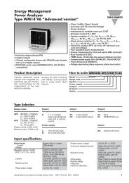
<strong>Electronic</strong> <strong>motor</strong> <strong>protection</strong> <strong>relay</strong><br />
Type CET 4 - ordering information<br />
Description Cat. No.<br />
CET 4<br />
CET 4 basic unit panel mounted 1 )<br />
CET 4 basic unit panel mounted 2 )<br />
CET 4 + earth leakage for NSW MDA 14081 approved to AS 2081.3<br />
Current converters type CWE 4 (required for each CET 4 unit) 3 )<br />
0.5 to 2.5 amps or for use with 1 amp secondary current<br />
transformers (customers own CT’s)<br />
2.5 to 20 amps or for use with 5 amp secondary current<br />
transformers (customers own CT’s)<br />
20 to 180 amps 4 )<br />
160 to 630 amps standard type<br />
160 to 630 amps (new version)<br />
Option cards 5 ) supplied without connector sets<br />
Option card for DeviceNet communications<br />
Profibus card for CET 4<br />
Option card for modbus communications<br />
Option card for remote I/O communications<br />
Profibus card for personal computer 6 )<br />
(includes ‘Visu’ software)<br />
Option card CST 4<br />
(add ‘S’ to Cat. No. or order separately)<br />
Option card CLV 4<br />
(add ‘L’ to Cat. No. or order separately)<br />
Option card CMV 4 (RTD)<br />
(add ‘M’ to Cat. No. or order separately)<br />
Surface mounting set for CET 4<br />
Analogue output meter - use with option card 72 mm<br />
CST 4 (4-20 mA <strong>motor</strong> temperature rise) 96 mm<br />
CET 4 user manual - contains set up instructions application<br />
data and diagnostic information<br />
Adaptor plate for fitting CET 4 in place of CET 3<br />
(metal plate colour grey RAL 7035)<br />
CET 4 test unit for periodic performance testing of CET 4<br />
<strong>protection</strong> <strong>relay</strong>s<br />
CET 4 key switch - panel mounted (prevents unauthorised<br />
setting changes) [Lockout - reset - Normal - Emg start]<br />
Notes: 1 ) CET 4 can be supplied with option cards<br />
and control transformers 24, 36, 48,110,<br />
240 and 415 V AC.<br />
2 ) CET 4 can be supplied with option cards<br />
and power modules 24 - 48 V,120,<br />
and 220 V DC (extra price) power supplies.<br />
3 ) Supplied complete with 5 metre<br />
connection lead for plug-in to CET 4 unit.<br />
4 ) CWE 4-180 has CT openings for <strong>motor</strong><br />
cable- for connection bars.<br />
5 ) It is preferable that CET 4 option cards<br />
are fitted by <strong>NHP</strong> however customer<br />
retrofit is possible.<br />
i<br />
CET 4/…V AC<br />
CET 4/…V DC<br />
CET 4/…V AC/MD<br />
CWE 4-2.5A<br />
CWE 4-20A<br />
CWE 4-180A<br />
CWE 4-630A<br />
CWE 4-630N<br />
CDN4<br />
CPB 4<br />
CMB 4<br />
CRI 4<br />
CPC 4<br />
CST 4<br />
CLV 4<br />
CMV 4<br />
CPM 4<br />
CUD 4-72<br />
CUD 4-96<br />
CUM 4-SS<br />
CPA 4<br />
CTU 4<br />
LE 2-12-10028<br />
6 ) CPC 4 card can communicate with up to<br />
31 CET 4 units.<br />
i<br />
Available on indent only.<br />
240/415 V rated power supplies are<br />
suitable for use on 230/400 V in<br />
accordance with AS 60038 : 2000.
Refer catalogue CT<br />
Cat. No. CET 4<br />
Cat. No. CWE 4<br />
Rear view of CET 4 showing<br />
option cards being installed<br />
<strong>Electronic</strong> <strong>motor</strong> <strong>protection</strong> <strong>relay</strong><br />
Type CET 4 - general information<br />
CET 4 - a new standard in <strong>motor</strong> <strong>protection</strong><br />
The new microprocessor based electronic <strong>motor</strong> <strong>protection</strong> <strong>relay</strong> CET 4 continues the<br />
successful tradition of Sprecher + Schuh in the field of high quality <strong>motor</strong> <strong>protection</strong>.<br />
The CET 4 offers first class <strong>motor</strong> <strong>protection</strong> by use of the proven two body thermal<br />
representation. An extension of this system includes consideration of asymmetrical<br />
conditions and a facility for ambient or cooling temperature feedback if required.<br />
CET 4 - the ideal component for modern control systems<br />
Besides a variety of <strong>protection</strong> functions for different requirements, the microprocessor used<br />
gives way for the integration of the CET 4 into control systems. It provides information and<br />
functions that conventionally were difficult or costly to realise. Clear text readout in English<br />
on the <strong>relay</strong> (LCD display), and a communication option make setting, monitoring, failure<br />
tracking and data logging a simple task.<br />
All functions are easy to set and understand and the basic version can be extended by<br />
means of plug-in cards where additional control functions are required.<br />
Protection functions (basic unit)<br />
❍ Full thermal <strong>protection</strong> with thermal equivalent model<br />
❍ Asymmetry <strong>protection</strong> and phase failure detection<br />
❍ High overload or stalling <strong>protection</strong><br />
❍ Underload <strong>protection</strong><br />
❍ Earth fault <strong>protection</strong><br />
❍ Start time and starts per hour supervision<br />
❍ Warm start <strong>protection</strong><br />
Special settings and features (basic unit)<br />
❍ Selectable auto/manual reset of thermal trip<br />
❍ Adjustable thermal reset level<br />
❍ Cooling constant ratio <strong>motor</strong> on/off adjustable<br />
❍ Failsafe or non failsafe operation of trip <strong>relay</strong><br />
❍ Emergency start facility (modifies copper memory only)<br />
❍ Remote reset facility is standard<br />
❍ Alarm <strong>relay</strong> fitted on basic unit<br />
❍ Set-up disable input (security of set values)<br />
Current converter modules type CWE 4<br />
Only four CWE 4 current converter modules are required to cover the range of 0.5 to<br />
630 amps. Secure operation is assured as the CWE / CET 4 link is continuously monitored.<br />
The CET 4 also checks compatibility of the set current to the connected CWE module. Use<br />
on high or low voltage <strong>motor</strong>s is possible.<br />
Adjustable warning functions (basic unit)<br />
❍ Thermal overload pre-warning<br />
❍ Asymmetry level<br />
❍ High overload (approaching stall)<br />
❍ Earth fault<br />
❍ Underload activated<br />
Modular design for flexibility<br />
The modular system design permits economical and appropriately specified solutions:<br />
❍ Extra features can be added as required<br />
❍ Plug-in option cards allow the operational requirements to be optimally matched<br />
❍ The current converter module covers a wide range. This simplifies selection and planning
Refer catalogue CT<br />
CET 4 display – actual values.<br />
CET 4 display – set values<br />
CET 4 display – recorded<br />
values<br />
Typical CET 4 option card<br />
<strong>Electronic</strong> <strong>motor</strong> <strong>protection</strong> <strong>relay</strong><br />
Type CET 4 - general information<br />
Operating data display (actual values)<br />
Comprehensive information can be displayed on the LCD display in plain text to facilitate and<br />
simplify management of operations. The following data can be requested:<br />
❍ Average <strong>motor</strong> current ❍ Individual phase currents<br />
❍ Thermal utilisation percent ❍ Time to trip (if in overload mode)<br />
❍ Asymmetry percent ❍ Earth current<br />
❍ Time to reset (if tripped) ❍ Temperature levels (if used)<br />
Set parameters display (set values)<br />
Setting the parameters (set points) on a clear LCD display requires only four keys. The<br />
result:<br />
❍ The CET 4 is simple and fast to set up - initially and during operation<br />
❍ Simple and rapid malfunction tracing<br />
❍ Up to 130 set points and adjustments are available from the front keypad<br />
Note: The front keypad is protected to IP 65 as standard<br />
Statistical data (recorded values)<br />
The basic CET 4 stores all important data in non volatile memory (EEPROM). The internal<br />
elapsed time clock operates for up to eight hours on loss of control voltage. This allows the<br />
re-calculation of <strong>motor</strong> thermal capacity when the control supply is restored and provides a<br />
means of logging the time and duration of momentary power failures. The statistical data<br />
recorded includes:<br />
❍ CET 4 operating time ❍ Time since last trip<br />
❍ Motor running hours ❍ Time since four previous trips<br />
❍ Time since last start ❍ Cause of last trip<br />
❍ Time since the four previous starts ❍ Cause of four previous trips<br />
❍ Number of starts ❍ Number of trips on each function<br />
❍ Current, asymmetry, earth current, max. temperature before last trip<br />
Option cards<br />
CMV 4 option card CPB 4 option card<br />
❍ Six RTD inputs (PT 100) RS 485 profibus communication card for<br />
❍ One ambient input (PT 100) CET 4.<br />
CLV 4 option card CPC 4 option card<br />
❍ Phase sequence input RS 485 profibus communication card for<br />
❍ Two extra output <strong>relay</strong>s which can personal computer.<br />
be programmed for auto star/delta<br />
starter control or for other functions<br />
❍ Complete with ‘visu’ software<br />
CST 4 option card<br />
❍ Earth leakage using core balance ❍ Three extra (assignable) output <strong>relay</strong>s<br />
transformer ❍ Two control inputs for special functions<br />
❍ PTC thermistor input ❍ 4-20 mA analogue output for <strong>motor</strong><br />
❍ Relay for short circuit <strong>protection</strong> temperature rise<br />
Communication cards<br />
❍ DeviceNet<br />
❍ Profibus (FMS)<br />
❍ Modbus<br />
❍ Remote I/O
Refer catalogue CT<br />
CET 4 basic unit<br />
Option card CPB 4<br />
<strong>Electronic</strong> <strong>motor</strong> <strong>protection</strong> <strong>relay</strong><br />
Type CET 4 - ordering information<br />
Catalogue Number structure CET 4 main unit<br />
Basic unit<br />
Control voltage<br />
24 V AC<br />
36 V AC<br />
48 V AC<br />
110 V AC<br />
230/240 V AC<br />
400/415 V AC<br />
24-48 V DC<br />
110 V DC<br />
Option card<br />
S = CST 4<br />
Option card<br />
L = CLV 4<br />
} Only one of these cards can be used<br />
M = CMV 4<br />
Option card (communications)<br />
D = CDN 4 Device net card<br />
P = CPB 4 Profibus card (FMS)<br />
B = CMB 4 Modbus card<br />
R = CRI 4 Remote I/O card<br />
CET 4 / . . . . / S / L / P<br />
Basic unit main features<br />
Thermal overload, asymmetry, high overcurrent/stalling, underload, earth fault, warm start,<br />
emergency start, start time monitoring, alarm contact, remote reset, operating data display<br />
(LCD), statistical data, adjustable trip and warning levels, starts per hour inhibit, setting<br />
disable input.<br />
CST 4 option card<br />
Provides additional output <strong>relay</strong>s Nos 1, 2, 3, programmable to any function. Input for core<br />
balance current transformer (earth leakage). Input for thermistor (PTC), two control inputs for<br />
selectable functions including new full load current (two speed <strong>motor</strong> application), speed<br />
switch (stall during start <strong>protection</strong>), on/off delay timers, disable of selected <strong>protection</strong><br />
functions. 4-20 mA analogue output for <strong>motor</strong> temperature rise. Use of short circuit<br />
<strong>protection</strong> function via <strong>relay</strong> No. 1.<br />
CLV 4 option card (cannot be used if CMV 4 card is installed)<br />
Provides additional output <strong>relay</strong>s Nos 4 & 5, programmable to any function or assigned for<br />
automatic star delta starter control (changeover based on time or when current drops below<br />
1.1 x I e).<br />
❍ Provision for phase sequence (voltage) input and also functions as voltage loss<br />
<strong>protection</strong> on one phase. (Normal phase failure <strong>protection</strong> is via asymmetry)<br />
CMV 4 option card (cannot be used if CLV 4 card is installed)<br />
Provides six RTD inputs (PT 100) for stator or bearing temperature measurement. A further<br />
RTD input is provided for ambient or coolant temperature input (considered in thermal<br />
model).<br />
Communications cards<br />
❍ CDN 4 DeviceNet card<br />
❍ Profibus communication card (FMS)<br />
❍ CMB 4 Modbus card<br />
❍ CRI 4 remote I/O card<br />
Note: 240/415 V rated power supplies are suitable for use on 230/400 V in accordance<br />
with AS 60038 : 2000
Refer catalogue CT<br />
<strong>Electronic</strong> <strong>motor</strong> <strong>protection</strong> <strong>relay</strong><br />
Type CET 4 - dimensions and mounting<br />
CET 4 panel mounted 1 ) CET 4 flush mounting<br />
10<br />
144<br />
144<br />
max. 6 mm<br />
Note: 1 ) Using optional CPM mounting set. Mounting depth 139 mm (allow for wiring)<br />
CWE 4-180<br />
Without busbars Straight busbars For use with CA 6<br />
The <strong>motor</strong> leads can be fed directly<br />
through the openings of the current<br />
monitoring module.<br />
I e = 20…180 A<br />
IEC conductor cross-section:<br />
4…95 mm2. CWE 4-2.5<br />
CWE 4-20<br />
ø max, 19 mm<br />
Generally CWE 4-2.5 and CWE 4-20<br />
are used for secondary applications<br />
with additional main current<br />
transformers.<br />
For 1 A secondary CTs use CWE 4-2.5.<br />
For 5 A secondary CTs use CWE 4-20.<br />
sprecher +<br />
schuh<br />
CET 4<br />
138 +1 -0<br />
138 +1<br />
-0<br />
10<br />
139<br />
137<br />
149
Refer catalogue CT<br />
CWE 4-630N<br />
Control circuit (basic unit)<br />
<strong>Electronic</strong> <strong>motor</strong> <strong>protection</strong> <strong>relay</strong><br />
Type CET 4 - dimensions and wiring<br />
Main connections CET 4 - CWE 4<br />
Direct connection of CWE<br />
(primary application)<br />
CET 4<br />
Connection of main<br />
CT’s to CWE 4<br />
Dimensions (mm)<br />
a b c c1 ød d1 d2 d3 øe øe1 e2<br />
155 145 156 118 6.3 6.3 135 88 11 M10 48<br />
K1 Contactor CA<br />
F1 <strong>Electronic</strong> <strong>motor</strong> <strong>protection</strong> <strong>relay</strong> CET 4<br />
S1 On button<br />
S0 Off button<br />
Us Control voltage<br />
H1 Indicator “contactor closed”<br />
H2 Indicator “CET 4 tripped”<br />
MR Main output <strong>relay</strong><br />
AL Alarm <strong>relay</strong><br />
H3 Indicator “alarm / warning”<br />
Connection of CT’s and core balance CT<br />
(also possible with 3 main CT’s)
Refer catalogue CT<br />
Connection diagram<br />
PT<br />
100<br />
# 1<br />
PT<br />
100<br />
# 2<br />
PT<br />
100<br />
# 3<br />
PT<br />
100<br />
# 4<br />
PT<br />
100<br />
# 5<br />
PT<br />
100<br />
# 6<br />
PT<br />
100<br />
# 7<br />
Front keypad<br />
<strong>Electronic</strong> <strong>motor</strong> <strong>protection</strong> <strong>relay</strong><br />
Type CET 4 - technical information<br />
CMV 4 / CLV 4 CST 4 Basic<br />
1T1<br />
1T3<br />
1T2<br />
2T1<br />
2T3<br />
2T2<br />
3T1<br />
3T3<br />
3T2<br />
4T1<br />
4T3<br />
4T2<br />
5T1<br />
5T3<br />
5T2<br />
6T1<br />
6T3<br />
6T2<br />
7T1<br />
7T3<br />
7T2<br />
1 3 5<br />
CWE 4<br />
2 4 6<br />
M<br />
3 ~<br />
Aux<br />
Relay # 4<br />
Aux<br />
Relay # 5<br />
T<br />
F<br />
100 mA<br />
F<br />
53<br />
54<br />
63<br />
64<br />
100 mA<br />
L1<br />
L2<br />
L3<br />
L1<br />
L2<br />
L3<br />
Aux<br />
Relay # 1<br />
Aux<br />
Relay # 2<br />
Aux<br />
Relay # 3<br />
A 4… 20 mA<br />
23<br />
24<br />
33<br />
34<br />
Control — Y31<br />
Input # 1 — Y32<br />
Control — Y41<br />
Input # 2 — Y42<br />
PTC<br />
— T1<br />
— T2<br />
Core — K<br />
Balance — I<br />
43<br />
44<br />
Main Relay MR<br />
Supply<br />
Emerg.<br />
Start<br />
Disable<br />
Settings<br />
Remote<br />
Reset<br />
Alarm<br />
Relay AL<br />
Non-Fail-Safe Fail-Safe<br />
A1-<br />
A2+<br />
The electronic <strong>motor</strong> <strong>protection</strong> system CET 4 is very easy to operate. With six<br />
foil keys and the LCD, all functions, data and tests can be entered, executed or<br />
displayed. On the single-line LCD all available data and functions are displayed.<br />
1 Values: Selection of mode.<br />
Actual values: Indication of actual operational data.<br />
Set values: Setting mode (set/vary, store parameters).<br />
Recorded values: Indication of statistical data.<br />
97<br />
98<br />
95<br />
96<br />
Y11<br />
Y12<br />
Y13<br />
Y21<br />
Y22<br />
2 Select: Select function and enter/change operating parameters.<br />
3 Settings: Enable entry (change) and memorise (enter).<br />
4 Test: Test functions.<br />
5 Reset: Reset trips.<br />
6 LCD: Single line.<br />
Two lines of text are displayed alternately.<br />
7 Fault indicator (LED).<br />
Flashing: Warning.<br />
Steady state: Trip.<br />
13<br />
14<br />
95<br />
96<br />
97<br />
98
Refer catalogue CT<br />
Protective functions<br />
Description<br />
Basic unit CET 4<br />
Thermal overload<br />
Asymmetry (phase failure)<br />
High overload / stalling<br />
Underload<br />
Underload delayed enable<br />
Earth fault (Holmgreen)<br />
Starting time monitor<br />
Limited starts per hour<br />
Optional board CST 4<br />
Short circuit<br />
Earth fault (core balance c.t.)<br />
Stalling during start 2 )<br />
Thermistor input (PTC)<br />
Optional board CLV 4<br />
Phase sequence (voltage)<br />
Phase failure (voltage)<br />
Optional boards CMV 4<br />
PT 100 input #1…#6 (stator, bearings)<br />
PT 100 input #7 3 )<br />
<strong>Electronic</strong> <strong>motor</strong> <strong>protection</strong> <strong>relay</strong><br />
Type CET 4 - technical data<br />
Function<br />
Factory<br />
setting<br />
On<br />
On<br />
On<br />
Off<br />
On<br />
On<br />
Off<br />
Off<br />
Off<br />
Off<br />
Off<br />
Off<br />
Off<br />
Off<br />
Off<br />
Off<br />
Setting<br />
range<br />
25…100 %<br />
-<br />
10…100 %<br />
-<br />
1…10<br />
4…12 I e<br />
5…500 mA<br />
-<br />
-<br />
-<br />
-<br />
50…200 °C<br />
-<br />
Factory<br />
setting<br />
0.5-2000 A 4 ) 20 A<br />
5…80 % 35 %<br />
1…6 I e 2.4I e<br />
75 %<br />
-<br />
50 %<br />
-<br />
2<br />
10 I e<br />
5 mA<br />
-<br />
-<br />
-<br />
-<br />
50 °C<br />
-<br />
Tripping delay/time<br />
Factory<br />
Range setting<br />
1-600 s 5 )<br />
1…25 s<br />
0.1…5 s<br />
1…60 s<br />
0…240 s<br />
0.1…5 s<br />
1…240 s<br />
-<br />
Warning functions<br />
Note: The level to which the warnings are set must be such that the alarm picks up before the trip.<br />
-<br />
-<br />
-<br />
-<br />
10 s<br />
2.5 s<br />
0.5 s<br />
10 s<br />
0 s<br />
0.5 s<br />
10 s<br />
-<br />
20…990 ms 50 ms<br />
0.1…5 s 0.5 s<br />
-<br />
-<br />
-<br />
260 ms<br />
Basic unit CET 4<br />
Thermal utilisation (%∆ϑ load) Off<br />
Asymmetry (% I e)<br />
Off<br />
High overload (I e)<br />
Off<br />
Underload<br />
Optional board CST 4<br />
Off<br />
Earth fault (core balance C.T.) Off<br />
Off<br />
Notes: 1 ) One <strong>relay</strong> per function can be selected: MR = Main <strong>relay</strong>, AL + Alarm <strong>relay</strong>, <strong>relay</strong>s 1…5.<br />
2 ) Via external speed switch (control input 1), output <strong>relay</strong> as per high overload.<br />
3 ) Allowing for the ambient temperature in the thermal image.<br />
4 ) Also use as a secondary <strong>relay</strong> (any current with CT ratios selected).<br />
5 ) Locked rotor current also adjustable 2.5 - 12 x Ie.<br />
6 ) Primary sensitivity – CT ratio can also be selected.<br />
6 50…99 % 75 % -<br />
5…80 % 20 % -<br />
1…6I e 2I e -<br />
25…100 75 % -<br />
)<br />
Optional board CMV<br />
5 mA…50 A 1 A -<br />
PT 100 input #1…#6 (stator, bearings)<br />
50…200 °C 50 °C -<br />
1 s<br />
2 s<br />
< 3 s<br />
-<br />
-<br />
-<br />
-<br />
-<br />
-<br />
-<br />
Relays 1 )<br />
selection<br />
MR<br />
All<br />
All<br />
All<br />
-<br />
All<br />
All<br />
All<br />
#1<br />
All<br />
All<br />
MR<br />
All<br />
All<br />
All<br />
-<br />
Factory<br />
setting<br />
MR<br />
MR<br />
MR<br />
MR<br />
-<br />
MR<br />
MR<br />
MR<br />
-<br />
MR<br />
MR<br />
MR<br />
MR<br />
MR<br />
MR<br />
-<br />
AL,#1…#5 AL<br />
AL,#1…#5 AL<br />
AL,#1…#5 AL<br />
AL,#1…#5 AL<br />
AL,#1…#5 AL<br />
AL,#1…#5 AL
Refer catalogue CT<br />
Control functions<br />
Description<br />
Basic unit CET 4<br />
Warm start (% of ‘cold’ trip)<br />
On<br />
Emergency override of thermal trip<br />
Option board CST 4<br />
Off<br />
On<br />
Off<br />
Off<br />
Off<br />
Off<br />
Off<br />
Off<br />
Off<br />
Off<br />
Off<br />
Off<br />
Off<br />
Off<br />
Off<br />
Off<br />
Off<br />
Off<br />
Off<br />
Off<br />
Off<br />
Off<br />
Off<br />
Off<br />
3 )<br />
Analog output <strong>motor</strong> current<br />
Analog output therm. utilisation<br />
Analog output PT 100 temperature<br />
Control input #1: (24 V AC/DC; 8 mA)<br />
Alternatively one of 3 functions<br />
can be selected:<br />
❍ Pickup delay, <strong>relay</strong> #2<br />
❍ Dropout delay, <strong>relay</strong> #2<br />
❍ Switch off prot. functions:<br />
- Asymmetry / phase failure<br />
- High overload/stalling<br />
- Earth fault<br />
- Short circuit<br />
- Underload<br />
- Limit starts/hour<br />
- PTC<br />
- PT 100<br />
Control input #2: (24 V AC/DC; 8 mA)<br />
Alternatively one of 4 functions<br />
can be selected:<br />
❍ Pickup delay, <strong>relay</strong> #3<br />
❍ Dropout delay, <strong>relay</strong> #3<br />
❍ Set 2nd rated current 2 )<br />
- Asymmetry/phase failure<br />
- High overload/stalling<br />
- Earth fault<br />
- Short circuit<br />
- Underload<br />
- Limited starts/hour<br />
- PTC<br />
- PT 100<br />
Optional board CLV 4<br />
Star delta starting<br />
<strong>Electronic</strong> <strong>motor</strong> <strong>protection</strong> <strong>relay</strong><br />
Type CET 4 - technical data<br />
Function<br />
Factory<br />
setting<br />
Setting<br />
range<br />
50…100 %<br />
Jumper term.<br />
4…20 mA (20 mA=200 % Ie, 12 mA=100 % Ie)<br />
4…20 mA -<br />
- -<br />
4…20 mA (20 mA=200 °C, 12 mA=100 °C)<br />
-<br />
-<br />
-<br />
-<br />
-<br />
-<br />
-<br />
-<br />
-<br />
-<br />
-<br />
-<br />
-<br />
0.5…2000 A<br />
-<br />
-<br />
-<br />
-<br />
-<br />
-<br />
-<br />
-<br />
Factory<br />
setting<br />
70 %<br />
Y11-Y12<br />
-<br />
-<br />
-<br />
-<br />
-<br />
-<br />
-<br />
-<br />
-<br />
-<br />
-<br />
-<br />
-<br />
20 A<br />
-<br />
-<br />
-<br />
-<br />
-<br />
-<br />
-<br />
Y-∆ at<br />
1.1 I e<br />
Tripping delay/time<br />
Factory<br />
Range setting<br />
4…60 min 60 min<br />
- -<br />
0…240 s<br />
0…240 s<br />
-<br />
-<br />
-<br />
-<br />
-<br />
-<br />
-<br />
-<br />
-<br />
0…240 s<br />
0…240 s<br />
-<br />
-<br />
-<br />
-<br />
-<br />
-<br />
-<br />
-<br />
Y-∆ at<br />
1…240 s<br />
Notes: 1 ) One <strong>relay</strong> per function can be selected: MR = Main <strong>relay</strong>, AL + Alarm <strong>relay</strong>, <strong>relay</strong>s 1…5.<br />
2 ) Eg. two-speed <strong>motor</strong>s.<br />
3 ) Analogue output can be selected for either thermal utilisation, <strong>motor</strong> current or PT 100 temperature.<br />
0 s<br />
0 s<br />
-<br />
-<br />
-<br />
-<br />
-<br />
-<br />
-<br />
-<br />
-<br />
0 s<br />
0 s<br />
-<br />
-<br />
-<br />
-<br />
-<br />
-<br />
-<br />
-<br />
10 s<br />
Relays 1 )<br />
selection<br />
-<br />
-<br />
-<br />
-<br />
-<br />
-<br />
-<br />
-<br />
-<br />
-<br />
-<br />
-<br />
-<br />
-<br />
-<br />
-<br />
-<br />
-<br />
-<br />
-<br />
-<br />
-<br />
-<br />
-<br />
-<br />
Factory<br />
setting<br />
-<br />
-<br />
#2<br />
#2<br />
-<br />
-<br />
-<br />
-<br />
-<br />
-<br />
-<br />
-<br />
-<br />
#3<br />
#3<br />
-<br />
-<br />
-<br />
-<br />
-<br />
-<br />
-<br />
-<br />
Y: #4<br />
∆: #5
Refer catalogue CT<br />
<strong>Electronic</strong> <strong>motor</strong> <strong>protection</strong> <strong>relay</strong><br />
Type CET 4 - technical information<br />
Ambient conditions<br />
Temperature<br />
Operation -5…+60 °C<br />
Storage -40…+60 °C<br />
Transport -40…+85 °C<br />
Climatic sensitivity<br />
Damp heat IEC 68-2-3 40 °C, 92 % Relative humidity, 56 days<br />
Climatic cycling IEC 68-2-30 25/40 °C, 21 cycles<br />
Degree of <strong>protection</strong><br />
CET 4, enclosed in panel IP 65<br />
Terminals IP 20<br />
Resistance to vibration<br />
- as per IEC 68-2-6 10 … 150 Hz, 3 g<br />
Resistance to shock<br />
- as per IEC 68-2-27 30 g, shock duration 18 ms, semisinusoidal<br />
in x, y, z - directions<br />
Nominal rated voltages U e<br />
Primary circuit of detection<br />
CWE 4-2.5 A; CWE 4-180 A;<br />
CWE 4-20 A; CWE 4-630 A<br />
Motor circuit<br />
- as per IEC, SEV, VBE 0660 660 V AC 1000 V AC<br />
- as per CSA, UL 600 V AC 600 V AC<br />
Control circuits<br />
Main <strong>relay</strong> (MR) 95…98, supply A1, A2<br />
Phase sequence <strong>protection</strong> L 1, L 2, L3<br />
- as per IEC 947 400/415 V AC<br />
- as per SEV 380 V AC<br />
- as per UL, CSA 230/240 V AC<br />
Alarm <strong>relay</strong>s (AL) 13/14<br />
Auxiliary <strong>relay</strong>s #1, #4, #5<br />
- as per IEC 947 400/415 V AC<br />
- as per SEV 250 V AC<br />
- as per UL, CSA 240 V AC<br />
Auxiliary <strong>relay</strong>s #2, #3 50 V AC / 30 V DC<br />
Control inputs #1, #2 24 V AC / 24 V DC<br />
Electrical tests<br />
Test voltage CWE 4-2.5 A; CWE 4-180 A;<br />
CWE 4-20 A; CWE 4-630 A<br />
Motor circuit<br />
- as per IEC 947-1 U imp 6 kV, U imp 8 kV<br />
Control circuit<br />
Between control circuits and to all other circuits 1 )<br />
Main <strong>relay</strong> (MR) 95…98, supply A1, A2<br />
Phase sequence <strong>protection</strong> L 1, L 2, L 3<br />
Alarm <strong>relay</strong> (AL), Auxiliary <strong>relay</strong>s #1…5<br />
Control inputs #1, #2<br />
Core balance c. t. k, l<br />
- as per IEC 947-1 U imp 4 kV<br />
EMC standard<br />
Noise emission as per EN 50081-1/2<br />
Noise proof as per EN 50082-1/2<br />
Supply<br />
Nominal supply voltage U e<br />
50/60 Hz, 110 V AC; 220…240 V;<br />
400…415 V; 440 V<br />
DC 24…48 V, 110 V/120 V, 220 V<br />
Permissible voltage fluctuation AC 0.85…1.1 U e<br />
DC 0.8…1.1 U e<br />
Power consumption AC 13 VA<br />
DC 10 W max.<br />
Short-circuit <strong>protection</strong> appropriate conductor cross section of cable.<br />
The supply module is proofed against short<br />
circuits.<br />
Note: 1 ) The measuring inputs for PT 100 and PTC, the 4…20 mA output and the RS 485 interface<br />
are not insulated from one another.<br />
240/415 V rated power supplies are suitable for use in 230/400 V in accordance with<br />
AS 60038 : 2000
<strong>Electronic</strong> <strong>motor</strong> <strong>protection</strong> <strong>relay</strong><br />
Type CET 4 - technical information<br />
Relays<br />
Contact data of output <strong>relay</strong>s<br />
Main <strong>relay</strong> (MR) 95…98<br />
Contacts fitted 1 N/C and 1 N/O galvanically separated<br />
Service voltage [V] 24 48 60 110 220/230 230/240 380<br />
400/415<br />
- as per UL, CSA: pilot duty 240 V<br />
440<br />
Continuous thermal current [A] 4 4 4 4 4 4 4 4 4<br />
Rated service current on AC<br />
Rated service current on DC<br />
[A] 4 4 4 4 3 3 2 2 1.5<br />
- without prot. network, L/R = 35 ms [A] 0.6 0.3 0.25 0.15 0.05 0.05 - - -<br />
- with prot. network 1 ), L/R = 100 ms [A] 0.6 0.6 0.5 0.5 0.5 0.5 - - -<br />
Max. permissible switching current [A] 44 44 44 44 33 33 22 22 16.5<br />
Alarm <strong>relay</strong> (AL), auxiliary <strong>relay</strong>s #1, #4, #5<br />
Contacts fitted 1 N/O each<br />
Continuous thermal current 4 A<br />
Max. permissible switching voltage<br />
Nominal service current<br />
400/415 V AC, 125 V DC<br />
- cosϕ = 1 4 A at 250 V AC and 30 V DC<br />
- cosϕ = 0.4 L/R = 7 ms<br />
Max. switching power<br />
2 A at 250 V AC and 30 V DC<br />
- cosϕ = 1 1250 VA, 150 W<br />
- cosϕ = 0.4 L/R = 7 ms 500 VA, 60 W<br />
- as per UL / CSA<br />
Auxiliary <strong>relay</strong>s #2, #3<br />
230/240 V, 1A pilot duty<br />
Contacts fitted 1 N/O each<br />
Continuous thermal current 4 A<br />
Max. permissible switching voltage<br />
Max. switching power<br />
30 V DC / 48 V AC<br />
- cosϕ = 1 150 W<br />
- cosϕ = 0.4 L/R 7 ms<br />
Terminals<br />
60 W<br />
CET 4 plug-in terminals Range of cross-section: 0.5…2.5 mm2 , single wire<br />
0.5…1.5 mm2 , double wire<br />
- as per UL 2.2…14 AWG<br />
- as per VDE nominal 1.5 mm2 Main circuit<br />
- CWE 4-2.5 A / CWE 4-20 A Terminals<br />
- CWE 4-180 A Insertion opening or current bars 20 x 4 mm<br />
- CWE 4-630 A Current bars 25 x 8 mm<br />
Main current transformers for the <strong>motor</strong> circuit<br />
When CET 4 is used as a secondary <strong>relay</strong> with CWE 4-2.5 A / CWE 4-20 A<br />
Recommended CT in the phases<br />
Min. nominal service voltage Nominal service voltage of <strong>motor</strong><br />
Min. rated primary current I 1n<br />
Nominal service current of <strong>motor</strong><br />
Rated secondary current 1 A or 5 A<br />
Class and nominal overcurrent factor 5 P 10 ext. 120 % 2 )<br />
Power rating According to power consumption in leads and measuring circuit<br />
Rated frequency 50/60 Hz<br />
Burden: CET 4 + CWE 4-2.5 A CET 4 + CWE 4-20 A<br />
- Power consumption at max. rated current 3 Refer catalogue CT<br />
) 0.1 VA/phase 0.4 VA/phase<br />
- Thermal limit current continuous 3 A 24 A<br />
- Thermal limit current 1 s 250 A 600 A<br />
- Frequency of input current<br />
General notes on CWE 4<br />
50/60 Hz 50/60 Hz<br />
No-load<br />
Core balance current transformer<br />
Recommended data for core balance CT<br />
Secondary no-load permitted, as burden is mounted in detection module<br />
Nominal ratio<br />
Burden: measuring circuit CET 4<br />
Kn =<br />
minimum detectable earth-fault<br />
pickup current of earth-fault prot. CET 4<br />
- Power consumption at rated current (0.5 A) 0.4 VA<br />
- Limiting thermal current, continuous 0.5 A<br />
- Limiting thermal current for 1 s 25 A<br />
- Frequency of input current 50/60 Hz<br />
Notes: 1 ) Max. rated current of fuse: rapid (D) 16 A; slow (DT) 10 A.<br />
2 ) Protection current transformer (P = <strong>protection</strong>) ± 1 % error at rated current; ± 5 % error at rated overcurrent (10 x rated current).<br />
Rated thermal current = 120 % rated current (if I e <strong>motor</strong> > 87 % of rated current transformer current).<br />
With starting current 10: I e: class 5 P 20. The current transformer error adds up to the CET 4 error.<br />
3 ) 2.5 A with CWE 4-2.5 A, 20 A with CWE 4-20 A.<br />
240/415 V rated power supplies are suitable for use on 230/400 V in accordance with AS 60038 : 2000