Concrete Light - Possibilities and Visions
Concrete Light - Possibilities and Visions
Concrete Light - Possibilities and Visions

Create successful ePaper yourself
Turn your PDF publications into a flip-book with our unique Google optimized e-Paper software.
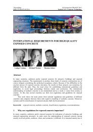
Proceedings fib Symposium PRAGUE 2011<br />
ISBN 978-80-87158-29-6 Keynote Plenary Lectures<br />
CONCRETE LIGHT - POSSIBILITIES AND VISIONS<br />
Manfred Curbach Silke Scheerer<br />
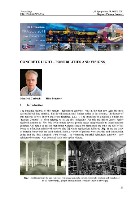
1 Introduction<br />
The building material of the century - reinforced concrete - was in the past 100 years the most<br />
successful building material. This it will remain until further notice in this century. The history of<br />
this material is well known <strong>and</strong> often described, e.g. [1]. The invention of a hydraulic binder, the<br />
"Roman Cement", is often referred to as the first milestone. For this the Briton James Parker<br />
received a patent in 1796. Mid-19th century several people began independently to insert iron into<br />
concrete. On behalf of all the Frenchman Coignet should be mentioned. He built the roof of his<br />
house as a flat, iron-reinforced concrete slab [1]. Other applications followed (Fig. 1) <strong>and</strong> the study<br />
of material behaviour has been pushed. Soon, a variety of patents were awarded <strong>and</strong> construction<br />
codes <strong>and</strong> the first st<strong>and</strong>ards were written. The composite material reinforced concrete - later<br />
reinforced concrete - was born <strong>and</strong> could take up his victory.<br />
Fig. 1 Buildings from the early days of reinforced concrete construction; left: cooling <strong>and</strong> warehouse<br />
in St. Petersburg [2]; right: market hall in Wroclaw (built in 1908) [3]<br />
29
fib Symposium PRAGUE 2011 Proceedings<br />
Keynote Plenary Lectures ISBN 978-80-87158-29-6<br />
One was aware of the significance of this invention well. Therefore, it was thought in the first half<br />
of the previous century, innovations in construction are no longer possible. Known is, for example,<br />
the anecdote that Professor Finsterwalder should have advised his son – Ulrich Finsterwalder -<br />
against studying civil engineering [4]. It should hardly be expected with new inventions, as the<br />
state of the art is already so high - that was the opinion of a renowned professor at the beginning of<br />
the 1920s.<br />
That this view was wrong we know today. To increase the capacity of the conventional<br />
reinforced concrete, steel was prestressed. Later Ulrich Finsterwalder himself developed together<br />
with colleagues the still used Dywidag-prestressing method or the cantilever method. With this<br />
construction method bridges with spans up to 300 m have been built till today [5]. Beside bridges,<br />
for example, shell structures, whose heyday between 1960 <strong>and</strong> 1970 was (Fig. 2), also show<br />
particularly impressive the performance of the reinforced concrete as building material <strong>and</strong> the<br />
performance of the different, always new developed Construction methods. In the 1980s, an<br />
innovation jam started, that lasted until the early 1990s.<br />
30<br />
Fig. 2 Reinforced concrete shell by Heinz Isler (built in 1968) [6]<br />
In the recent past, the researchers can look back on a number of innovations. On the one h<strong>and</strong> the<br />
development of more efficient concretes - the so-called concretes of the new generation - was<br />
pushed successfully. On the other h<strong>and</strong>, the search for new type tensile reinforcement materials was<br />
intensified as the susceptibility to corrosion of conventional reinforcing steel the engineer often<br />
forces to construct components thicker than would be required static. And just herein was <strong>and</strong> is<br />
a major research focus of the Institute of <strong>Concrete</strong> Structures of the TU Dresden.<br />
2 The beginning of research on textile reinforced concrete (TRC)<br />
at the TU Dresden<br />
The search for alternative material combinations had the goal to open up new design possibilities<br />
<strong>and</strong> uses for concrete construction through improved material properties. In the mid-1990s,<br />
Dresden researchers had the idea to insert textile fabrics of non-corrosive endless filaments with<br />
a very high tensile strength instead of the corrodible reinforcing steel into concrete, which only has<br />
a very low tensile strength.<br />
But the idea of embedding fibres into brittle materials is not new. Already thous<strong>and</strong>s of years<br />
ago was the straw mixed with clay. The bricks produced from it were then more resistant to<br />
cracking, for example, due to the large temperature fluctuations during the day [7]. In modern<br />
times, since the early 1990s fibre concrete has developed as an alternative to steel-reinforced<br />
normal concrete. In this type of concrete short fibres made of steel, polymer or glass will be added.<br />
Besides an increase in compressive <strong>and</strong> tensile strength, the r<strong>and</strong>omly oriented fibres have
Proceedings fib Symposium PRAGUE 2011<br />
ISBN 978-80-87158-29-6 Keynote Plenary Lectures<br />
especially positive effect on the bending tensile strength. Therefore, fibre-reinforced concrete is<br />
often used in highly loaded industrial floors.<br />
The use of endless filaments or of fabrics made of such filaments as a substitute for common<br />
reinforcement was still a very new approach. Among experts, the new, innovative composite<br />
material is now well-known as textile reinforced concrete or TRC. After initial experiments (Fig. 3)<br />
with textiles made from alkali-resistant glass (AR glass) had delivered promising results, 1999, the<br />
Collaborative Research Centre 528 "Textile Reinforcements for Structural Strengthening <strong>and</strong><br />
Repair" (in short: SFB 528) was launched at TU Dresden [8].<br />
Fig. 3 First specimens of textile concrete: window lintels with polystyrene core; right: first experimental<br />
results<br />
The newly developed construction material is characterized primarily by its lightness combined<br />
with high load capacity. Typical component thicknesses are 1-3, in exceptional cases up to<br />
5 centimetres. The reinforcement is flexible. Thereby curved forms can be realized much easier<br />
than with reinforced concrete. TRC is suitable for fabrication of new components <strong>and</strong> for<br />
strengthening of existing ones. Components strengthened with TRC have a significant higher load<br />
bearing capacity. At the same time deformations are limited, e.g. deflection of plates or beams.<br />
Also noteworthy is the characteristic crack pattern of TRC. In contrast to reinforced concrete<br />
cracks occur in a much smaller distance with very low crack width (Fig. 4).<br />
The lightness of the innovative composite construction material is not only important in<br />
terms of its own dead weight. This property also brings effective relief to the construction workers<br />
in the practical application. Thus, the textile fabric can be cut with scissors <strong>and</strong> easily applied by<br />
h<strong>and</strong> without the use of heavy equipment. The fine grained concrete can be applied, for example,<br />
with trowel <strong>and</strong> spatula or with a commercial spraying device.<br />
Fig. 4 Crack pattern of a plate reinforced with TRC after 4-point bending test<br />
31
fib Symposium PRAGUE 2011 Proceedings<br />
Keynote Plenary Lectures ISBN 978-80-87158-29-6<br />
3 The construction material TRC<br />
Textile reinforced concrete consists of two components - the textile fabric <strong>and</strong> a special fine<br />
grained concrete. In contrast to fibre-reinforced concrete, in which the reinforcing fibres are<br />
embedded undirected, the TRC is made of fabrics of continuous fibres. Fig. 5 shows a comparison<br />
between glass <strong>and</strong> carbon yarns <strong>and</strong> common reinforcement. The individual yarns are arranged<br />
oriented in the fabric, whereby the tensile reinforcement can be designed similar to the reinforcing<br />
steel in reinforced concrete according to the strength flow in the component. A detailed description<br />
can be found in [9]. Here only briefly the most important terms explained (Fig. 6).<br />
32<br />
Fig. 5 Size comparison for reinforcements (from top to bottom): glass roving, carbon roving, reinforcing<br />
steel (Øs = 14 mm), prestressing str<strong>and</strong> (A = 15 mm²), [9]<br />
Fig. 6 Manufacturing of textile reinforced concrete
Proceedings fib Symposium PRAGUE 2011<br />
ISBN 978-80-87158-29-6 Keynote Plenary Lectures<br />
Basic element of the textile fabric is the single continuous fibre - the so-called filament. For TRC,<br />
we use AR-glass fibres or carbon fibres. The glass melt is enriched with a certain percentage<br />
zirconium, which makes the glass insensitive to the alkaline attack in the concrete matrix. The<br />
diameter of a single AR-glass fibre varies according to the producer between 14 to 28 mm.<br />
A carbon fibre is with a diameter of about 7 mm significantly thinner [9]. In comparison, a human<br />
hair is at least up to 120 mm thick [10].<br />
The single filaments are combined into fibre bundles - also called multifilament yarns or<br />
rovings. One roving usually contains several hundred single filaments which lie parallel to each<br />
other without rotation. Before single AR-glass or carbon filaments are combined into a yarn, the<br />
sizing is applied. This special chemical solutions effect for example surface improvements of the<br />
filaments, make the filaments suppler <strong>and</strong> more resistant against mechanical stress [11].<br />
On textile machines, the rovings are processed into textile fabrics. At the TU Dresden<br />
several textile machines are available. The fabrics can be produced from AR-glass, carbon or<br />
a combination of both fibre types. The number of yarn layers <strong>and</strong> the fabric geometry depend on<br />
the specific application (Fig. 7).<br />
Fig. 7 Examples for different fabrics; left: carbon fabric with typical dimensions; middle: fabric for shear<br />
force strengthening; right: fabric for bending strengthening<br />
For the application of this textile fabrics a special mineral matrix - the so-called fine grained<br />
concrete - was developed at the Technical University of Dresden. The maximum aggregate size of<br />
this concrete has typically a diameter of 1 mm. This size resulted from the dimension of the<br />
reinforcement on the one h<strong>and</strong> <strong>and</strong> the intended low layer thicknesses on the other. According to<br />
common definition such a matrix is classified as a mortar. Due to the mechanical properties of the<br />
material, however, the term fine grained concrete was chosen. As binder a combination of cement,<br />
fly ash <strong>and</strong> microsilica is used. The quantitative ratios <strong>and</strong> the type of cement depend on the<br />
intended use of the TRC. In addition to the water plasticizer is still added.<br />
The mechanical properties of hardened concrete are determined according to DIN EN 1015-<br />
11:2007-05 T2 (mortar; pressure <strong>and</strong> bending tensile strength) <strong>and</strong> according to DIN 1048-5<br />
(elastic modulus of concrete) on prismatic samples (4 × 4 × 16 cm) respectively. Because of its<br />
high compressive strength the fine grained concrete can be classified as high-strength concrete.<br />
Examples for typical mix proportions <strong>and</strong> resulting mechanical properties are given in Tab. 1.<br />
TRC can be made in different ways. Basically, so far three methods have been applied:<br />
• lamination,<br />
• spraying,<br />
• injection,<br />
at which the third variant currently is of secondary importance. When laminating, first one few<br />
millimetres thick layer of fine concrete is applied to a prepared surface or into a mould. Then<br />
alternately, previously cut textile fabric <strong>and</strong> thin layers of fine concrete matrix are placed. The fine<br />
grained concrete can, for example, be spread with a trowel <strong>and</strong> smoothed before the next layer of<br />
33
fib Symposium PRAGUE 2011 Proceedings<br />
Keynote Plenary Lectures ISBN 978-80-87158-29-6<br />
fabric carefully placed <strong>and</strong> lightly pressed into the fresh matrix. Least the final layer of fine<br />
concrete is smoothed. The manufacture of TRC by spraying differs from laminating only in the<br />
way of concrete applying (Fig. 8). This is no longer made by h<strong>and</strong> but with the help of a spraying<br />
device, such as those used when applying render. The concrete curing is similar to conventional<br />
concrete.<br />
Tab. 1 Examples of sprayable concrete mixtures <strong>and</strong> mechanical properties of the fine concretes, according<br />
to [9]<br />
34<br />
Constituent / Property Mix 1 Mix 2 Mix 3<br />
S<strong>and</strong> 0-1 [kg/m³] 942,0 1122,4 1122,4<br />
Cement CEM I 32,5 [kg/m³] – 564,8 –<br />
Cement CEM III/B 32,5 [kg/m³] 628,0 – 468,4<br />
Microsilica (suspension) [kg/m³] 100,5 56,6 56,6<br />
Fly ash [kg/m³] 265,6 253,1 253,1<br />
Water [l/m³] 214,6 221,5 221,5<br />
superplasticizer FM30, BASF [l/m³] 10,5 12,0 –<br />
superplasticizer ACE30, BASF [l/m³] – – 3,8<br />
Water/binder ratio [–] 0,33 0,36 0,42<br />
Compressive strength [N/mm²] 76 65 54<br />
Bending tensile strength [N/mm²] 7,1 8,7 9,5<br />
Modulus of elasticity [N/mm²] 28.500 25,600 –<br />
Density [kg/dm³] 2,17 – –<br />
Fig. 8 Applying of a TRC strengthening layer by spraying (Photos: Silvio Weil<strong>and</strong>)<br />
In the case of strengthening the ground must be carefully prepared. First, by s<strong>and</strong>blasting the<br />
surface is roughened. After the removal of dust or loose concrete particles the ground is moistened.<br />
Now, with the application of fine concrete matrix can be started.<br />
4 Experimental researches<br />
Before a new building material can be used in practice, it has to prove itself in experiments. The<br />
material behaviour must be explored <strong>and</strong> described. Calculation methods must be developed. Some
Proceedings fib Symposium PRAGUE 2011<br />
ISBN 978-80-87158-29-6 Keynote Plenary Lectures<br />
research results are presented here in brief. The focus of our research is the use of textile concrete<br />
to increase load bearing capacity of existing reinforced concrete structures. The most common<br />
loading scenarios are bending, shear <strong>and</strong> torsion or exposure to normal forces.<br />
Fig. 9 4-point bending tests on a strengthened slab (Photo: Silvio Weil<strong>and</strong>)<br />
Fig. 10 Comparison of different fabrics for flexural strengthening of reinforced concrete slabs [12]<br />
For components with insufficient bending bearing capacity TRC is applied in the tensile zone. The<br />
fine grained concrete layers are just a few millimetres thick. The total thickness of the TRC layer is<br />
thus dependent on the number of textile layers. The potential of strengthening with TRC could be<br />
impressively demonstrated in numerous experiments. The experimental setup is shown in Fig. 9. At<br />
this single-span ceiling panels, the TRC layer at the bottom of the component is applied. The<br />
reinforcement layer ends before the supports. Exemplary results are shown in Fig. 10. In the<br />
35
fib Symposium PRAGUE 2011 Proceedings<br />
Keynote Plenary Lectures ISBN 978-80-87158-29-6<br />
illustrated test results the number of textile layers <strong>and</strong> the type of the fibres <strong>and</strong> fabrics were varied.<br />
The load carrying capacity could be increased up to twice the reference plate in three cases. The<br />
significantly more rigid behaviour of the strengthened plates at identical loads is also remarkable,<br />
which is interesting especially for changes of use of buildings <strong>and</strong> in terms of the deflection<br />
restrictions.<br />
At ceiling panels are mainly the bending bearing capacity <strong>and</strong> the deflections positively<br />
impacted by a TRC strengthening. At beams <strong>and</strong> T-beams is often the shear capacity critical,<br />
especially in buildings from the early days of reinforced concrete construction. The inclination of<br />
the AR-glass fibres in the main load direction of the fabric is adapted in the direction of the<br />
principal stresses in the web with an angle of ±45° ([13] <strong>and</strong> Fig. 11). The particular difficulty at<br />
such components is the anchoring of the textile reinforcement. Especially at T-beam the pressure<br />
zone is generally not accessible to the strengthening works.<br />
36<br />
Fig. 11 Shear force strengthening in the laboratory [14]<br />
Fig. 12 Test set up for torsion tests [15]
Proceedings fib Symposium PRAGUE 2011<br />
ISBN 978-80-87158-29-6 Keynote Plenary Lectures<br />
Torsion is relevant for example for edge beams, electricity pylons etc. Therefore, rod-shaped<br />
reinforced concrete components have been strengthened with TRC <strong>and</strong> investigated experimentally<br />
in torsion tests. The experimental setup is shown in Fig. 12, exemplary test results in Fig. 13.<br />
Fig. 13 Exemplary results from torsion tests on specimen with circular cross section [15]<br />
Also as subsequent reinforcement of columns, textile reinforced concrete has proven [16]. For<br />
example, at 2 m high columns load increases between 35 % <strong>and</strong> 66 % were obtained even with two<br />
AR-glass fabric layers, depending on the kind of textile. In the recent past, compression tests were<br />
made on large-sized columns in a new 10-MN testing machine, (Fig. 14, [17] <strong>and</strong> [18]).<br />
Fig. 14 Experiments on large-scale columns; left: experimental setup; Middle: reinforced concrete columns<br />
with <strong>and</strong> without reinforcing carbon fabric after the test; right: fine, evenly distributed cracks by<br />
a strengthened column (Photos: Christian Dittrich <strong>and</strong> Ulrich van Stipriaan)<br />
37
fib Symposium PRAGUE 2011 Proceedings<br />
Keynote Plenary Lectures ISBN 978-80-87158-29-6<br />
An unstrengthened reference column of common reinforced concrete <strong>and</strong> two, with 5 layers of<br />
carbon fabric reinforced components were examined. As expected, the load bearing capacity of the<br />
strengthened columns could be significantly increased to almost the double value compared to the<br />
reference column. Impressively, however, was especially the much more ductile failure<br />
mechanism. Strengthening with carbon fabric <strong>and</strong> fine concrete caused, that many fine cracks<br />
distributed over the circumference <strong>and</strong> the height of the column before the maximum load was<br />
reached <strong>and</strong> failure occurred. At the purely reinforced concrete column the damage focused on the<br />
upper part of the component. The prescribed effects are documented also in Fig. 14.<br />
5 Practical applications of textile reinforced concrete<br />
5.1 Strengthening of components<br />
Without the built environment is our life today would be unthinkable. Habitation, employment,<br />
transport, utilities - everything that is impossible without buildings or roads. Nevertheless the<br />
building stock must be maintained <strong>and</strong> preserved as a permanent new building would be neither<br />
financially feasible nor environmentally acceptable. Environmental influences or modified load<br />
scenarios can cause, that an existing construction a loading can not longer withst<strong>and</strong> safely. In<br />
bridge building play, for example, the increased traffic <strong>and</strong> higher axle loads a role. Therefore, our<br />
focus is on practical application of TRC in light, stable strengthening of existing elements. A few<br />
outst<strong>and</strong>ing examples are introduced below.<br />
The first major project was the increase of the load bearing capacity of a hypar shell over the<br />
"big lecture hall” at FH Schweinfurt revisited [19]. The already built in the 1960s reinforced<br />
concrete shell has a maximum span of about 39 m <strong>and</strong> in many areas this thickness of the shell is<br />
only 8 cm. This structure had to be urgently repaired <strong>and</strong> the load bearing capacity had to be<br />
upgraded. In this project could be demonstrated for the first time the impressive benefits of the<br />
TRC in its practical application. In addition, the application of TRC was finally the only<br />
reinforcement method that could be realized in this building project. Neither the partly substantial<br />
roof pitch nor the expected high temperatures on the roof top represented a problem. Moreover, the<br />
2-dimensional TRC layer allows the dissipation of differently oriented forces into the shell.<br />
As expected, the processing of the building material was found be uncomplicated - <strong>and</strong> the<br />
layer thickness of 1.5 cm represented only a very small increase in dead weight of the roof<br />
structure. As a comparison, the usual thickness of shotcrete is 8 cm. In several steps alternating fine<br />
concrete layers <strong>and</strong> three layers of carbon fabric were applied within a few days on the whole roof.<br />
Meanwhile, the Institutes staff was permanently on site to advise <strong>and</strong> monitor the work itself <strong>and</strong><br />
the concrete curing. An impression of the construction work provides Fig. 8.<br />
38<br />
Fig. 15 Cross section of the roof structure to be strengthened [20]
Proceedings fib Symposium PRAGUE 2011<br />
ISBN 978-80-87158-29-6 Keynote Plenary Lectures<br />
In Zwickau a l<strong>and</strong>marked barrel-vault from the early days of reinforced concrete should be<br />
preserved [20]. At this historic building (built in 1903) the dem<strong>and</strong>s made by the planner, the<br />
preservationists <strong>and</strong> the users were high. Above all, the geometry of the shell should be largely<br />
preserved. Fig. 15 shows a cross section through the 8 cm thick, corrugated reinforced concrete<br />
slab with a rectangular window openings <strong>and</strong> one of the eleven beams that are connected to the<br />
plate monolithic. As at the project in Schweinfurt, with none of the conventional methods could all<br />
the conditions are fulfilled. Only TRC came into consideration.<br />
Once the existing plaster had been removed, the surface of the old concrete was roughened<br />
by s<strong>and</strong> blasting. In addition, existing defects were repaired. Thereafter, the surface was wetted <strong>and</strong><br />
the first layer of fine concrete was sprayed. Subsequently, the previously cut textile fabric made of<br />
carbon yarns was embedded into the fresh fine grained concrete. Successively, all of the five static<br />
required reinforcement layers have been applied. As a final layer were again sprayed 3 mm fine<br />
concrete. The thickness of the strengthening layer was again with a total of 1.5 cm extraordinarily<br />
low. Finally, there was a seven-day concrete curing to prevent shrinkage cracks. The various steps<br />
are illustrated in Fig. 16.<br />
But the use of textile reinforced concrete for strengthening is not limited to those special<br />
constructions described above. This shows a construction project from 2009. In a multi-storey<br />
commercial building had to be strengthened more than 2200 m² of the ceiling. The bending load<br />
capacity had not been sufficient. Strengthening with shotcrete or CFRP plates had to be excluded<br />
for constructive <strong>and</strong> technical reasons. Therefore, the structural safety has been restored with<br />
a layer of textile reinforced concrete.<br />
a) Prepared reinforced concrete structure b) Spraying a fine grained concrete layer [20]<br />
c) Application of carbon fabric into the fine concrete (right photo: [20])<br />
39
fib Symposium PRAGUE 2011 Proceedings<br />
Keynote Plenary Lectures ISBN 978-80-87158-29-6<br />
40<br />
d) Ready TRC surface e) Roof structure after reopening of the building<br />
(photo: [21])<br />
Fig. 16 Strengthening light made - documentation of the strengthening of a barrel-vault<br />
5.2 New components<br />
TRC is not only a "lightweight" strengthening method. “<strong>Concrete</strong> light” is also possible at new<br />
components or structures. Outst<strong>and</strong>ing examples are two segmental bridges made of textile<br />
reinforced concrete, which were built under the leadership of the Institute of <strong>Concrete</strong> Structures.<br />
The world's first textile reinforced concrete bridge was built for the National Garden Festival<br />
in 2006 over the Döllnitz in Oschatz (Saxony). The lightweight, innovative bridge construction<br />
convinced the scientific community - <strong>and</strong> was awarded: in 2006 with the "Special Encouragement<br />
Award" of the Fédération Internationale du béton (fib) <strong>and</strong> in 2007 with the “Innovation Award of<br />
the concrete components supply industry”. In the fall of 2007, a second, 17 m long foot <strong>and</strong> cycle<br />
bridge in Kempten (Allgäu) was opened to the public [22]. The 18 u-shaped elements of the<br />
sweeping bridge over the Rottach were prepared by spraying method at the precast plant in<br />
Oschatz.<br />
Fig. 18 shows the cross-section of the bridge in Oschatz. The reinforcement of the elements<br />
consisted mainly of AR-glass fabric, arranged in four layers. The only 3 cm thick TRC-shell is<br />
footway, railing <strong>and</strong> supporting structure all in one. Longitudinal stiffeners, stiff transversal rib on<br />
the element edges <strong>and</strong> enlargements of cross section in the areas of the h<strong>and</strong>rails <strong>and</strong> at the bottom<br />
corners give the slender shell shape stability (Fig. 17).<br />
Fig. 17 Cross-section of the TRC bridge in Oschatz [22]<br />
After completion of all individual segments (Fig. 18), the single elements were aligned on<br />
a falsework <strong>and</strong> checked for fitting accuracy. Then, the individual segments were glued together<br />
step by step. By temporarily clamping together the all-over filling of the joints was guaranteed.
Proceedings fib Symposium PRAGUE 2011<br />
ISBN 978-80-87158-29-6 Keynote Plenary Lectures<br />
After all of the individual segments were connected, the bridge was longitudinally prestressed by<br />
monostr<strong>and</strong>s. The entire bridge could be transported to their location as special transport. The<br />
bridge today shows Fig. 19.<br />
Fig. 18 Prefabricated elements before clamping together [22]<br />
Fig. 19 TRC bridge in Kempten/Allgäu (Photo: Harald Michler)<br />
But not only light bridges can be realized in textile reinforced concrete. Another promising future<br />
field of applications are wall panels from TRC. Our institute is cooperating closely with industry<br />
partners to achieve easy <strong>and</strong> economical solutions. Conventional reinforced concrete facades are<br />
very massive because of the corrosion protection of steel reinforcement this is necessary. Due to<br />
the high dead load extensive anchoring systems are required [22].<br />
Taking into account also the needs of thermal protection, there are usually high layer<br />
thicknesses, which makes conventional, prefabricated wall panels unattractive in many cases.<br />
41
fib Symposium PRAGUE 2011 Proceedings<br />
Keynote Plenary Lectures ISBN 978-80-87158-29-6<br />
A promising alternative are the thin-wall TRC panels of Hering Bau GmbH & Co. KG (Fig. 20). In<br />
addition to use for covering new buildings, the system is due to its low dead weight suitable<br />
particular in the improvement in building stock [22]. Also, an anchor in less stable ground is<br />
possible.<br />
6 Outlook<br />
42<br />
Fig. 20 BetoShell facade elements made of TRC<br />
<strong>Concrete</strong> <strong>and</strong> light weight - TRC is a way to resolve this apparent contradiction.<br />
Textile reinforced concrete st<strong>and</strong>s for:<br />
• Innovation,<br />
• <strong>Light</strong> weight constructions,<br />
• Flexibility,<br />
• Unconventional shape <strong>and</strong><br />
• Unusual solutions.<br />
TRC has potential for building maintenance, as well as new construction.<br />
Fig. 21 Preliminary study for a new textile reinforced concrete bridge
Proceedings fib Symposium PRAGUE 2011<br />
ISBN 978-80-87158-29-6 Keynote Plenary Lectures<br />
After 12 years of intensive research funding of the SFB 528 by the German Research Foundation<br />
(DFG) in summer will end. The research activities of the SFB 528 are now being continued<br />
especially in practically oriented projects <strong>and</strong> in the Deutsches Zentrum für Textilbeton (DZT)<br />
[23]. Research <strong>and</strong> application of TRC will continue to be a research priority at the Institute of<br />
<strong>Concrete</strong> Structures of the TU Dresden, even after termination of the SFB 528. Already, more<br />
interesting projects are planned, e.g. a new bridge for pedestrians <strong>and</strong> cyclists (Fig. 21).<br />
We will also pursue other approaches to advance the lightweight construction with concrete.<br />
With particular interest we will pursue the results of the DFG priority program "<strong>Concrete</strong> light.<br />
Future concrete structures using bionic, mathematical <strong>and</strong> engineering formfinding principles”, its<br />
coordination is our responsibility. The aim of this interdisciplinary program is to initiate<br />
a paradigm change in construction: towards the light building with concrete away from the solid<br />
building as a st<strong>and</strong>ard in the "ordinary" building, not just as a special solution in leading individual<br />
projects.<br />
References<br />
[1] Ramm, W.: Über die faszinierende Geschichte des Betonbaus. In: Gebaute Visionen. 100<br />
Jahre Deutscher Ausschuss für Stahlbeton 1907-2007, Beuth Verlag GmbH Berlin · Wien ·<br />
Zürich, 2007, S. 27-130.<br />
[2] http://www.e-pics.ethz.ch/index/ETHBIB.Bildarchiv/ETHBIB.Bildarchiv_Hs_1085-1912-1-<br />
547_41533.html.<br />
[3] Kind-Barkauskas, F.; Kauhsen, B.; Polónyi, S.; Br<strong>and</strong>t, J.: Beton Atlas, Entwerfen mit<br />
Stahlbeton im Hochbau. Beton-Verlag Düsseldorf 1995; Reference thre to: Klimek, S.:<br />
Breslau.<br />
[4] Schambeck, Herbert: Ulrich Finsterwalder. In: Stiglat, Klaus, Bauingenieure und ihr Werk,<br />
Verlag Ernst & Sohn, Berlin, 2004.<br />
[5] Fergestad S, Aas-Jakobsen A (1999) <strong>Light</strong> Weight <strong>Concrete</strong> in Norwegian Bridges. 5th<br />
International Symposium on Utilisation of High Strength/High Performance <strong>Concrete</strong>, June<br />
1999, S<strong>and</strong>efjord, Norway, pp. 66-74.<br />
[6] http://commons.wikimedia.org/wiki/File:Deitingen_Sued_Raststaette,_Schalendach<br />
_01_09.jpg.<br />
[7] Rienecker, F.; Maier, G.: Lexikon zur Bibel. Brockhaus Verlag Wuppertal, 6. Auflage 2006.<br />
[8] http://sfb528.tu-dresden.de/.<br />
[9] Jesse, F.; Curbach, M.: Verstärken mit Textilbeton. In: Bergmeister, K.; Fingerloos, F.;<br />
Wörner, J.-D. (Hrsg.): Beton-Kalender 2010. Teil I, Berlin : Ernst & Sohn, 2009, S. 457-565.<br />
[10] http://de.wikipedia.org/wiki/Haar.<br />
[11] Scheffler, C.; Gao, S.-L.; Plonka, R.; Mäder, E.; Hempel, S.; Butler, M.; Mechtcheringe, V.:<br />
Interphase modification of alkali-resistant glass fibres <strong>and</strong> carbon fibres for textile reinforced<br />
concrete. Part I: Fibre properties <strong>and</strong> durability, Part II: Water adsorption <strong>and</strong> composite<br />
interphases. Composites. Science <strong>and</strong> Technology 69 (2009) pp. 531-538, 905-912.<br />
[12] Weil<strong>and</strong>, S.; Curbach, M.: Interaktion gemischter Bewehrungen bei der Verstärkung von<br />
Stahlbeton mit textilbewehrtem Beton. In: Curbach, M. (Hrsg.), Jesse, F. (Hrsg.): Textile<br />
Reinforced Structures : Proceedings of the 4th Colloquium on Textile Reinforced Structures<br />
(CTRS4) und zur 1. Anwendertagung, Dresden, 3.-5.6.2009. SFB 528, Technische<br />
Universität Dresden, D–01062 Dresden : Eigenverlag, 2009, S. 553-564 – ISBN 978-3-<br />
86780-122-5 RN: urn:nbn:de:bsz:14-ds-1244051366655-25294.<br />
[13] Brückner, A.; Ortlepp, R.; Curbach, M.: Textile Reinforced <strong>Concrete</strong> for Strengthening in<br />
Bending <strong>and</strong> Shear. In: Materials <strong>and</strong> Structures 39 (2006) 8, S. 741–748 – doi:<br />
10.1617/s11527-005-9027-2.<br />
43
fib Symposium PRAGUE 2011 Proceedings<br />
Keynote Plenary Lectures ISBN 978-80-87158-29-6<br />
[14] Ortlepp, R.; Brückner, A.; Curbach, M.: Influence of textile reinforcement on the principle<br />
stress condition. Lecture held on 3rd International fib Congress, Washington, D.C., May 29 -<br />
June 2 2010.<br />
[15] Schladitz, F.; Curbach M.: Torsionsversuche an textilbetonverstärkten Stahlbetonbauteilen.<br />
Beton- und Stahlbetonbau 104 (2009) 12, S. 835-843 – doi:10.1002/best.200900043.<br />
[16] Ortlepp, R.; Curbach, M.: Verstärken von Stahlbetonstützen mit textilbewehrtem Beton. In:<br />
Beton- und Stahlbetonbau 104 (2009) 10, S. 681-689 – doi:/10.1002/best.200900034.<br />
[17] Schladitz, F.; Hampel, T.; Ortlepp, S.; Scheerer, S.: Eine neue 10 MN Prüfmaschine für<br />
großformatige Bauteile. zur Veröffentlichung angenommen bei der Zeitschrift Bautechnik.<br />
[18] Ortlepp, R.; Schladitz, F.; Curbach, M.: Textilbetonverstärkte Stahlbetonstützen. eingereicht<br />
bei der Zeitschrift Beton- und Stahlbetonbau.<br />
[19] Curbach, M.; Hauptenbuchner, B.; Ortlepp, R.; Weil<strong>and</strong>, S.: Textilbewehrter Beton zur<br />
Verstärkung eines Hyparschalentragwerks in Schweinfurt. In: Beton- und Stahlbetonbau 102<br />
(2007) 6, S. 353-361 – doi:10.1002/best.200700551.<br />
[20] Schladitz, F.; Lorenz, E.; Jesse, F.; Curbach M.: Verstärkung einer denkmalgeschützten<br />
Tonnenschale mit Textilbeton. Beton- und Stahlbetonbau 104 (2009) 7, S. 432-437 –<br />
doi:10.1002/best.200908241.<br />
[21] Ehlig, D.: Hochtemperaturverhalten von Textilbeton. Lecture held on DZT-Anwendertagung<br />
2010 in Dresden.<br />
[22] Curbach, M.; Michler, H.; Weil<strong>and</strong>, S.; Jesse, D. Textilbewehrter Beton – Innovativ! Leicht!<br />
Formbar! In: BetonWerk International 11 (2008) 5, S. 62-72.<br />
[23] http://textilbetonzentrum.de/.<br />
Prof. Dr.-Ing. Manfred Curbach<br />
� Institut für Massivbau, TU Dresden<br />
01062 Dresden, Germany<br />
☺ manfred.curbach@tu-dresden.de<br />
44<br />
Dr.-Ing. Silke Scheerer<br />
� Institut für Massivbau, TU Dresden