

Machine Ensat® installation - Precision Fasteners Inc.
Machine Ensat® installation - Precision Fasteners Inc.
Machine Ensat® installation - Precision Fasteners Inc.

You also want an ePaper? Increase the reach of your titles
YUMPU automatically turns print PDFs into web optimized ePapers that Google loves.
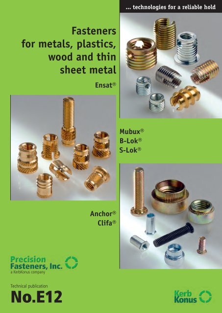
<strong>Fasteners</strong><br />
for metals, plastics,<br />
wood and thin<br />
sheet metal<br />
a KerbKonus company<br />
Technical publication<br />
No.E12<br />
<strong>Ensat®</strong><br />
Anchor®<br />
Clifa®<br />
... technologies for a reliable hold<br />
Mubux®<br />
B-Lok®<br />
S-Lok®
2<br />
Dimensions<br />
Threaded inserts from KerbKonus ...<br />
Index Page 2<br />
Tested quality Page 3<br />
Ensat – the self-tapping Page 4<br />
threaded insert; <strong>installation</strong> and 5<br />
Ensat ® -S 302 and <strong>Ensat®</strong>-SD 303<br />
M2 to M30 Self-tapping with very high Page 6<br />
2-56 to 1“ cutting slot<br />
or<br />
M2 to M10 As above, but in a very high Page 9<br />
special thin-walled<br />
version<br />
Ensat ® -SB 307/308 and <strong>Ensat®</strong>-SBD 347/348<br />
4-40 to 5/8-11 Self-tapping with very high Page 7<br />
or three cutting bores<br />
M3 to M10 As above, but in a very high Page 9<br />
4-40 to 3/8-16 special thin-walled<br />
version<br />
Ensat ® -SBS 337/338 and <strong>Ensat®</strong>-SBT 357/358<br />
M2 to M16 Self-tapping with very high Page 8<br />
4-40 to 5/8-11 three cutting bores<br />
as chip reservoirs<br />
Blind version additionally<br />
with closed floor<br />
Ensat ® -SI 302 2 and <strong>Ensat®</strong>-SBI 307 2/308 2<br />
M4 to M12 Self-tapping with very high Page 10<br />
8-32 to 7/16-14 cutting slot or with<br />
3 cutting bores and<br />
hexagonal socket<br />
Ensat <strong>installation</strong>…<br />
Manual and machine <strong>installation</strong> Page 11<br />
Screw-in tools…<br />
Tools 620/621/610/610 2 Page 12<br />
Ensat ® -SH 309 and <strong>Ensat®</strong>-SHI 309 2<br />
M2,5 to M16 Self-tapping or Page 13<br />
2-56 to 5/8-11 thread forming or<br />
hexagonal socket<br />
T-Lok 846 0/846 1<br />
M2,5 to M8 For embedding using high Page 15<br />
4-40 to 5/16-18 ultrasonic or heat<br />
transmission<br />
Mubux ® -A<br />
Product features<br />
Torque strength<br />
Other details<br />
M2 to M10 Press-in insert with Page 15<br />
2-56 to 3/8-16 helically knurled and 16<br />
also as threaded locking profile<br />
pin<br />
Dimensions<br />
B-Lok ®<br />
M2 to M8 Expansion insert with medium Page 17<br />
2-56 to 5/16-18 screw locking effect and 18<br />
S-Lok ®<br />
M2 to M10 For embedding using high Page 19<br />
2-56 to 5/16-18 ultrasound or mold in to 21<br />
also as threaded<br />
pin<br />
Anchor ® <strong>installation</strong><br />
Tools Page 22<br />
Anchor ® rivet bushing<br />
M2 to M16 Standard version high Page 23<br />
2-56 to 5/8-11<br />
Anchor ® -Mini<br />
M2 to M8 Weight and space- medium Page 24<br />
2-56 to 5/16-18 saving<br />
Clifa ® -Press-in nut and stud<br />
Product features and <strong>installation</strong> instructions Page 25<br />
Clifa ® -M<br />
M2 to M10 for metal high Page 26<br />
2-56 to 3/8-16<br />
Clifa ® -P<br />
M3 to M6 for metal high Page 27<br />
2-56 to 1/4-20<br />
Clifa ® -ABO<br />
M3 to M5 Press-in standoffs high Page 28<br />
4-40 to 10-24 thru-hole thread<br />
hexagon head<br />
Clifa ® -ABG<br />
M3 to M5 Press-in standoffs high Page 29<br />
4-40 to 10-24 blind thread<br />
hexagon head<br />
Clifa ® -SP/-SR/-SPD<br />
M2,5 to M8 for pressing-in flush medium Page 30<br />
3-48 to 5/16-18 to the surface.<br />
SP coarse teeth<br />
SR fine teeth<br />
SPD thin metal<br />
Clifa ® -SA/SAD<br />
Product features<br />
Torque strength<br />
Other details<br />
M3 to M10 for high loads drilled high Page 31<br />
4-40 to 3/8-16
DEKRA Certification<br />
zertifiziert<br />
What really counts:<br />
tested quality.<br />
Quality System<br />
Dekra Certificate in accordance with<br />
ISO 9001:2008 Reg.No. 30507428/1<br />
ISO/TS 16949:2009 Reg.No. 160507011/1<br />
ISO 14001:2004 Reg.No. 170507049/1<br />
At our parent plant in Amberg, we<br />
produce threaded inserts using efficient<br />
production methods. A team of qualified<br />
and highly motivated staff guarantees a<br />
consistent, high standard of production.<br />
The number of products manufactured<br />
over the company’s history reaches into<br />
the billions. State-of- the- art automation<br />
lines manufacture around the clock in a<br />
precise and high standard of quality.<br />
The efficient and low-cost production of<br />
large-scale product series is one of the<br />
strenghts on which we have based our<br />
success.<br />
But our high-volume production output in<br />
no way compromises flexibility. We are<br />
able to quickly and efficiently produce<br />
even small batches of nonstandard items.<br />
Our state of the art stock control system<br />
permits the reliable, prompt delivery<br />
of standard products, keeping your production<br />
running to schedule at all times<br />
and helping to minimize your ware -<br />
housing costs.<br />
We are particularly proud of a cost-toperformance<br />
ratio which ensures satisfied<br />
customers the world over. This has made<br />
KerbKonus a reputable and respected<br />
partner to industry in the global marketplace.<br />
Quality and environment are top priority<br />
issues at KerbKonus. Quality consciousness<br />
is a continuous thread running<br />
through every aspect of the company’s<br />
work and all its products and services.<br />
Quality is lived and breathed at Kerb -<br />
Konus.<br />
As manufacturer in the metal processing<br />
industry we are aware of our responsibility<br />
for an environmentally compatible<br />
production. With this in mind we follow<br />
up a policy of sensible resource spending<br />
and environmental friendly production<br />
both in our process engineering and our<br />
product range.<br />
... technologies for a reliable hold<br />
3
4<br />
The <strong>Ensat®</strong><br />
self-tapping threaded<br />
insert …<br />
Ensat is a self-tapping threaded<br />
insert with external and internal<br />
threads, cutting slots or cutting bores.<br />
A continuous process of further<br />
development has brought about a number<br />
of major improvements to product<br />
characteristics. These inserts are<br />
protected by German and also foreign<br />
patents.<br />
<strong>Ensat®</strong>-S 302<br />
(with cutting slot) is recommended for<br />
most application cases. In certain materials,<br />
this Ensat demonstates a minimal<br />
inward springing action, so creating a<br />
certain screw locking effect. If this effect<br />
is not required, we recommend using<br />
Ensat-SB 307/308.<br />
<strong>Ensat®</strong>-SB 307/308<br />
(with cutting bores) was developed for<br />
materials with difficult cutting properties.<br />
This insert has a thick wall and the<br />
cutting force is distributed over three<br />
cutting edges.<br />
The short version Ensat 307 is particularly<br />
suitable where minimal material<br />
thicknesses are involved.<br />
Thin-walled <strong>Ensat®</strong>-SD/SBD<br />
for applications involving special space<br />
conditions (residual wall thicknesses),<br />
and also suitable for driving using a<br />
thread tapping machine (same internal<br />
and external thread pitch).<br />
Slot version: Works Standard 303 Threehole<br />
version: Works Standard 347/348<br />
(see page 9).<br />
<strong>Ensat®</strong>-SBS 337/338<br />
with three chip reservoirs. Used<br />
primarily wherever only a small amount<br />
of chips may be permitted to occur during<br />
the tapping process (see page 8).<br />
<strong>Ensat®</strong>-SBT<br />
with closed floor for additional<br />
sealing from below. Works Standard<br />
357/358. Dimensions: see Works Standard<br />
337/338 (see page 8).<br />
<strong>Ensat®</strong>-3F 305 is a thread forming insert<br />
with 3 longitudinal grooves around<br />
ist periphery.<br />
Fields of application<br />
The Ensat is used throughout the entire<br />
metal and plastics processing industry.<br />
Automotive industry, passenger<br />
and commercial vehicles<br />
Engines, transmissions, wide range of<br />
supply parts such as side view mirrors,<br />
radiators, bumpers etc.<br />
Plant and equipment construction<br />
Flange joints, construction equipment,<br />
oil burners etc.<br />
Household appliance and office<br />
machinery production<br />
Vacuum cleaners, cameras, sun lamps,<br />
drills etc.<br />
Electrical and laboratory supplies<br />
Capacitors, heavy current, radio and<br />
telecommunication systems, dental<br />
technology equipment.<br />
Military applications<br />
Tanks, aircraft etc.<br />
3 chip reservoirs<br />
around the periphery<br />
<strong>Ensat®</strong>-SBS 337/338<br />
These cutting bores are shaped to serve<br />
as chip reservoirs. The chips created during<br />
the diving process are stored here<br />
and cannot drop into sensitive equipment<br />
parts. For additional sealing from<br />
below: Ensat with closed floor: Works<br />
Standard 357/358 Dimensions: See<br />
Works Standard 307/308 (see page 7).<br />
Product features<br />
The Ensat has a large effective shearing<br />
surface (E B), so ensuring a<br />
higher degree of pull-out strength,<br />
i.e. an Ensat M4 is often sufficient<br />
instead of a cut M5 thread.<br />
The Ensat is driven subsequently into<br />
the finished workpiece. This means a<br />
higher casting machine output, no<br />
rejects due to incorrectly cast-in insert<br />
components, no molding sand<br />
trapped in the thread.<br />
A pre-cast or pre-drilled retaining<br />
hole with normal tolerance requirements<br />
is sufficient for driving in the<br />
Ensat. The thread is always precisely<br />
positioned.<br />
The work steps required with wire<br />
inserts – thread tapping, breaking<br />
off trunnions etc. as well as costly<br />
wearing tools (special thread drills,<br />
limit plug gauges etc.) are not<br />
required with the Ensat-system.<br />
The Ensat is insensitive to small<br />
areas of shrinkage. The Ensat-system<br />
prevents damage caused by torn<br />
threads.<br />
Universal application for all types of<br />
plastic, thermoset plastics, thermoplastics,<br />
PU/PUR foam, fiberglass<br />
reinforced plastics, for hardwood and<br />
plywood, particle board and metal.<br />
Maximum strength values in comparison<br />
to other systems. The diagram<br />
illustrates the withdrawing force in<br />
thermoplastic materials: In thermoset<br />
plastics and glass fiber reinforced<br />
plastics, the values tend to be higher.
The <strong>Ensat®</strong><br />
in the workpiece ...<br />
Installation recommendation<br />
The Ensat should be processed approx.<br />
0.004 – 0.008 recessed. After pro -<br />
cessing, the Ensat can be immediately<br />
subjected to load. If the component<br />
material permits subsidence of the<br />
Ensat under load, the Ensat can only<br />
execute an axial movement of 0.004 to<br />
0.008. In other words, the pretension of<br />
the screw union is largely retained,<br />
loosening of the screw connection<br />
under dynamic load is impeded.<br />
Retaining hole<br />
The retaining hole can be simply drilled<br />
or already provided for in the casting.<br />
It is generally not necessary to countersink<br />
the hole. However, we do recommend<br />
that you take care not to warp<br />
the workpiece surface when screwing in<br />
the Ensat.<br />
Material thickness:<br />
Length of the Ensat = smallest<br />
admissible material thickness M.<br />
Depth of the blind hole:<br />
Minimum depth -T see Works Standard<br />
sheets, page 6 to 13.<br />
Guidline values for light alloys:<br />
W ≥ 0.004 to 0.024 E<br />
Guidline values for cast iron:<br />
W ≥ 0.012 to 0.02 E<br />
Guidline values for plastic:<br />
W ≥ 0.01 to 0.035 E<br />
E = Outside diameter of the<br />
Ensat [mm]<br />
Borehole diameter:<br />
Brittle, tough and hard materials call for<br />
a larger borehole than soft or elastic<br />
materials. For guideline values, see the<br />
table above.<br />
Edge distance:<br />
The smallest still admissible edge<br />
distance depends on the planned stress<br />
level and the elasticity of the material<br />
into which the Ensat is installed.<br />
Sinking the receiving hole<br />
For a clean fit of the Ensat flush with<br />
the surface, the following injection or<br />
pressed hole form is recommended:<br />
Chamfer soft to medium-hard plastics<br />
to 60°. For hard and brittle plastics: Preinject<br />
or pre-press with N = E + 0.008<br />
to 0.016. Sinking depth X ≥ pitch of the<br />
Ensat male thread.<br />
In molded parts made of glass fiber<br />
reinforced plastic, a high pull-out resistance<br />
is reached if the casting skin is<br />
removed in the receiving hole by drilling<br />
open.<br />
Avoid any tilting between the Ensat and<br />
the screw – under the head or in the<br />
thread. For this reason, in the case of<br />
adjusting screws the Ensat is driven in<br />
to a depth of ≥ 0.004. Studs must be<br />
fixed against the floor surface of the<br />
blind hole.<br />
... technologies for a reliable hold<br />
Example:<br />
Female thread 5/16-18, recommended<br />
Borehole diameter for:<br />
Light alloy workpiece (Rm=280N/mm²),<br />
<strong>Ensat®</strong>-S 302: 0.441 to 0.449<br />
<strong>Ensat®</strong>-SB 307/308: 0.441 to 0.445<br />
Plastic workpiece<br />
<strong>Ensat®</strong>-S 302: 0.429 to 0.441<br />
<strong>Ensat®</strong>-SB 307/308: 0.437 to 0.445<br />
In case of processing problems (e.g.<br />
extreme screw-in torque levels), it is<br />
generally of no consequence to choose<br />
a higher bore diameter. In case of<br />
doubt, it is worth testing this. For more<br />
information also please see technical<br />
publication 20 inserts for metal; or<br />
technical publication 30 inserts for<br />
plastic and wood.<br />
5
Application<br />
Threaded insert Ensat-S with<br />
cutting slot is a self-tapping<br />
fastener, vibration resistant<br />
screw joints with high loading<br />
capacity in materials with low<br />
shearing strength.<br />
Threaded insert<br />
– self-tapping –<br />
for use in: plastics, light metal alloys, hardwood<br />
Example for finding Self-tapping threaded insert Ensat-S to Works Standard series 302 with internal thread A = 10-24<br />
the article number made of case-hardened, zinc plated and yellow chromated, steel: Ensat-S 302 000 610. 160<br />
6 <strong>Precision</strong> <strong>Fasteners</strong> <strong>Inc</strong>. 24 WORLD’s FAIR DRIVE, UNIT D SOMERSET, NJ 08873 (800) 447-2077 FAX (732) 627-8424<br />
Ensat ® -S<br />
Works Standard<br />
302<br />
Materials Unhardened steel Article no. (fourth group of digits) … … … 100<br />
Case-hardened steel, zinc plated, clear chromated Article no. (fourth group of digits) … … … 110<br />
Case-hardened steel, zinc/nickel plated, transparent passivated Article no. (fourth group of digits) … … … 143<br />
Case-hardened steel, zinc plated, yellow chromated Article no. (fourth group of digits) … … … 160<br />
Stainless steel 1.4105 Article no. (fourth group of digits) … … … 400<br />
Stainless steel 1.4305 (AISI 303) Article no. (fourth group of digits) … … … 500<br />
Brass Article no. (fourth group of digits) … … … 800<br />
Other materials, designs and finishes on request<br />
Tolerances ISO 2768-m<br />
It is suitable for <strong>installation</strong> in<br />
the following materials:<br />
– Plastic, laminates<br />
– Hardwood, but also<br />
– Light alloys<br />
– Cast iron, brass, bronze<br />
NF metals<br />
All dimensions in inches unless otherwise noted<br />
Internal Article Internal Article External thread Length Guidline values for receiving Minimum<br />
thread no. thread no. hole dia. drill hole<br />
<strong>Inc</strong>h metric depth in<br />
sizes sizes case of<br />
Plastics Soft metals blind holes<br />
A A E P B L L T<br />
2-56 302 000 602 … M 2.5 302 000 025 … 4.5 mm 0.5 mm 0.236 0.161 to 0.165 0.165 to 0.169 0.315<br />
4-40 302 000 604 … M 3 302 000 030 … 5 mm 0.5 mm 0.236 0.181 to 0.185 0.185 to 0.189 0.315<br />
6-32 302 000 606 … M 3.5 302 000 035 … 6 mm 0.75 mm 0.315 0.217 to 0.22 0.22 to 0.224 0.394<br />
8-32 302 000 608 … M 4 302 000 040 … 6.5 mm 0.75 mm 0.315 0.236 to 0.24 0.24 to 0.244 0.394<br />
10-24 302 000 610 … M 5 302 000 050 … 8 mm 1 mm 0.393 0.287 to 0.295 0.295 to 0.299 0.512<br />
M 6 (a) 302 000 061 … 9 mm 1 mm 0.472 0.327 to 0.35 0.335 to 0.339 0.59<br />
1/4-20 302 000 625 … M 6 302 000 060 … 10 mm 1.5 mm 0.551 0.35 to 0.362 0.362 to 0.37 0.669<br />
5/16-18 302 000 631 … M 8 302 000 080 … 12 mm 1.5 mm 0.59 0.429 to 0.441 0.441 to 0.449 0.709<br />
3/8-16 302 000 637 … M 10 302 000 100 … 14 mm 1.5 mm 0.709 0.508 to 0.52 0.52 to 0.528 0.866<br />
7/16-14 302 000 644 … M 12 302 000 120 … 16 mm 1.5 mm 0.866 0.587 to 0.598 0.598 to 0.606 1.024<br />
1/2-13 302 000 650 … M 14 302 000 140 … 18 mm 1.5 mm 0.945 0.665 to 0.677 0.677 to 0.685 1.102<br />
5/8-11 302 000 662 … M 16 302 000 160 … 20 mm 1.5 mm 0.866 0.744 to 0.756 0.756 to 0.764 1.063<br />
M 18 302 000 180 … 22 mm 1.5 mm 0.945 0.823 to 0.835 0.835 to 0.843 1.142<br />
M 20 302 000 200 … 26 mm 1.5 mm 1.063 0.98 to 0.992 0.992 to 1 1.26<br />
3/4-10 302 000 675 … M 22 302 000 220 … 26 mm 1.5 mm 1.181 0.98 to 0.992 0.992 to 1 1.417<br />
M 24 302 000 240 … 30 mm 1.5 mm 1.181 1.138 to 1.15 1.15 to 1.157 1.417<br />
1"-8 302 000 600 … M 27 302 000 270 … 34 mm 1.5 mm 1.181 1.295 to 1.307 1.374 to 1.386 1.417<br />
M 30 302 000 300 … 36 mm 1.5 mm 1.575 1.307 to 1.315 1.386 to 1.394 1.811<br />
Thread Internal thread A: UNC/UNF as per class 2B<br />
metric as per ISO 6H<br />
External thread E: metric, tolerances in accordance with Works Standard<br />
Internal thread A: also avaiable as Unified National Fine (UNF)<br />
Remark 2-56 UNC/M2.5 only for materials with minimal strength, as the shearing resistance of the studs in the<br />
<strong>installation</strong> tools may be insufficient.
Application<br />
Threaded insert Ensat-SB with<br />
cutting bores is a self-tapping,<br />
fastener for the creation of<br />
wearfree, vibration high loading<br />
capacity in materials with higher<br />
shearing strength.<br />
Threaded insert<br />
– self-tapping –<br />
for use in: aluminium, aluminium alloy, magnesium, mild steel<br />
... technologies for a reliable hold<br />
<strong>Precision</strong> <strong>Fasteners</strong> <strong>Inc</strong>. 24 WORLD’s FAIR DRIVE, UNIT D SOMERSET, NJ 08873 (800) 447-2077 FAX (732) 627-8424<br />
Ensat ® -SB<br />
Works Standard<br />
307 and 308<br />
All dimensions in inches unless otherwise noted<br />
Example for finding Self-tapping threaded insert Ensat-SB to Works Standard series 307 with internal thread A = 10-24<br />
the article number made of case-hardened, zinc plated and yellow chromated, steel: Ensat-SB 307 000 610. 160<br />
Short design Works Standard 307<br />
Long design Works Standard 308<br />
Materials Unhardened steel Article no. (fourth group of digits) … … … 100<br />
Case-hardened steel, zinc plated, clear chromated Article no. (fourth group of digits) … … … 110<br />
Case-hardened steel, zinc/nickel plated, transparent passivated Article no. (fourth group of digits) … … … 143<br />
Case-hardened steel, zinc plated, yellow chromated Article no. (fourth group of digits) … … … 160<br />
Stainless steel 1.4105 Article no. (fourth group of digits) … … … 400<br />
Stainless steel 1.4305 (AISI 303) Article no. (fourth group of digits) … … … 500<br />
Brass Article no. (fourth group of digits) … … … 800<br />
Other materials, designs and finishes on request<br />
Tolerances ISO 2768-m<br />
It is suitable for <strong>installation</strong> in<br />
the following materials:<br />
– Duroplastics, thermoplastics plastics (with the<br />
execption of rubbersoft plastics < 100 Shore A)<br />
but also for<br />
– Aluminium and aluminium alloys<br />
– Magnesium alloys<br />
– Cast iron<br />
Internal Article Internal Article External thread Length Guidline values for receiving Minimum<br />
thread no. thread no. Special thread hole dia. drill hole<br />
<strong>Inc</strong>h metric depth in<br />
sizes sizes case of<br />
Plastics Soft metals blind holes<br />
A A E P B L L T<br />
4-40<br />
307 000 604 …<br />
308 000 604 …<br />
M 3<br />
307 000 030 …<br />
308 000 030 …<br />
5 mm<br />
5 mm<br />
0.6 mm<br />
0.6 mm<br />
0.157<br />
0.236<br />
0.181 to 0.185 0.185<br />
0.236<br />
0.315<br />
6-32<br />
307 000 606 …<br />
308 000 606 …<br />
M 3.5<br />
307 000 035 …<br />
308 000 035 …<br />
6 mm<br />
6 mm<br />
0.8 mm<br />
0.8 mm<br />
0.197<br />
0.315<br />
0.217 to 0.22 0.22<br />
0.276<br />
0.394<br />
8-32<br />
307 000 608 …<br />
308 000 608 …<br />
M 4<br />
307 000 040 …<br />
308 000 040 …<br />
6.5 mm<br />
6.5 mm<br />
0.75 mm<br />
0.75 mm<br />
0.236<br />
0.315<br />
0.236 to 0.24 0.24<br />
0.315<br />
0.394<br />
10-24<br />
307 000 610 …<br />
308 000 610 …<br />
M 5<br />
307 000 050 …<br />
308 000 050 …<br />
8 mm<br />
8 mm<br />
1 mm<br />
1 mm<br />
0.276<br />
0.394<br />
0.291 to 0.299 0.295 to 0.299<br />
0.354<br />
0.512<br />
1/4-20<br />
307 000 625 …<br />
308 000 625 …<br />
M 6<br />
307 000 060 …<br />
308 000 060 …<br />
10 mm<br />
10 mm<br />
1.25 mm<br />
1.25 mm<br />
0.315<br />
0.472<br />
0.366 to 0.374 0.37 to 0.374<br />
0.934<br />
0.591<br />
5/16-18 307 000 631 … 308 000 631 …<br />
M 8<br />
307 000 080 …<br />
308 000 080 …<br />
12 mm<br />
12 mm<br />
1.5 mm<br />
1.5 mm<br />
0.354<br />
0.551<br />
0.437 to 0.445 0.441 to 0.445<br />
0.433<br />
0.669<br />
3/8-16<br />
307 000 637 …<br />
308 000 637 …<br />
M 10<br />
307 000 100 …<br />
308 000 100 …<br />
14 mm<br />
14 mm<br />
1.5 mm<br />
1.5 mm<br />
0.394<br />
0.709<br />
0.515 to 0.524 0.52 to 0.524<br />
0.512<br />
0.866<br />
7/16-14 307 000 644 … 308 000 644 …<br />
M 12<br />
307 000 120 …<br />
308 000 120 …<br />
16 mm<br />
16 mm<br />
1.75 mm<br />
1.75 mm<br />
0.472<br />
0.866<br />
0.591 to 0.598 0.594 to 0.598<br />
0.591<br />
1.024<br />
1/2-13<br />
307 000 650 …<br />
308 000 650 …<br />
M 14<br />
307 000 140 …<br />
308 000 140 …<br />
18 mm<br />
18 mm<br />
2 mm<br />
2 mm<br />
0.551<br />
0.945<br />
0.669 to 0.677 0.673 to 0.677<br />
0.669<br />
1.102<br />
5/8-11<br />
307 000 662 …<br />
308 000 662 …<br />
M 16<br />
307 000 160 …<br />
308 000 160 …<br />
20 mm<br />
20 mm<br />
2 mm<br />
2 mm<br />
0.551<br />
0.945<br />
0.748 to 0.756 0.752 to 0.756<br />
0.669<br />
1.102<br />
Thread Internal thread A: UNC/UNF as per class 2B<br />
metric as per ISO 6H<br />
External thread E: Special thread with flattened thread root, tolerances,<br />
tolerances in accordance with Works Standard<br />
Special applications For chip-sensitive (e.g. electronic appliances): Also available with 3 closed cutting bores serving<br />
as chip reservoirs. Works Standard 337/338 – see page 8<br />
7
Application<br />
This special Ensat was developed<br />
primarily for applications in<br />
which chips – created by the<br />
self-tapping process – exert a<br />
detrimental effect and could<br />
cause serious damage or failure<br />
Example for finding Self-tapping threaded insert Ensat-SBS to Works Standard series 337 with internal thread A = 10-24<br />
the article number made of case-hardened, zinc plated and yellow chromated, steel: Ensat-SBS 337 000 610. 160<br />
Short design Works Standard 337<br />
Long design Works Standard 338<br />
Materials Unhardened steel Article no. (fourth group of digits) … … … 100<br />
Case-hardened steel, zinc plated, clear chromated Article no. (fourth group of digits) … … … 110<br />
Case-hardened steel, zinc/nickel plated, transparent passivated Article no. (fourth group of digits) … … … 143<br />
Case-hardened steel, zinc plated, yellow chromated Article no. (fourth group of digits) … … … 160<br />
Stainless steel 1.4105 Article no. (fourth group of digits) … … … 400<br />
Stainless steel 1.4305 (AISI 303) Article no. (fourth group of digits) … … … 500<br />
Brass Article no. (fourth group of digits) … … … 800<br />
Other materials, designs and finishes on request<br />
Tolerances ISO 2768-m<br />
Threaded insert<br />
– self-tapping with chip reservoirs –<br />
during subsequent operation of<br />
the installed assembly – for<br />
example in electronic equipment.<br />
The three cutting bores<br />
distributed around the periphery<br />
are formed as chip reservoirs.<br />
The chips created during the<br />
<strong>installation</strong> process are stored in<br />
these reservoirs and cannot drop<br />
into the sensitive equipment<br />
components.<br />
All dimensions in inches unless otherwise noted<br />
Internal Article Internal Article External thread Length Guidline values for receiving Minimum<br />
thread no. thread no. Special thread hole dia. drill hole depth<br />
<strong>Inc</strong>h metric in case of<br />
sizes sizes blind holes<br />
A A E P B L +0.004 T<br />
4-40<br />
307 000 604 …<br />
308 000 604 …<br />
M 3<br />
307 000 030 …<br />
308 000 030 …<br />
5 mm<br />
5 mm<br />
0.6 mm<br />
0.6 mm<br />
0.157<br />
0.236<br />
0.185<br />
0.236<br />
0.315<br />
6-32<br />
307 000 606 …<br />
308 000 606 …<br />
M 3.5<br />
307 000 035 …<br />
308 000 035 …<br />
6 mm<br />
6 mm<br />
0.8 mm<br />
0.8 mm<br />
0.197<br />
0.315<br />
0.22<br />
0.276<br />
0.394<br />
8-32<br />
307 000 608 …<br />
308 000 608 …<br />
M 4<br />
307 000 040 …<br />
308 000 040 …<br />
6.5 mm<br />
6.5 mm<br />
0.75 mm<br />
0.75 mm<br />
0.236<br />
0.315<br />
0.24<br />
0.315<br />
0.394<br />
10-24<br />
307 000 610 …<br />
308 000 610 …<br />
M 5<br />
307 000 050 …<br />
308 000 050 …<br />
8 mm<br />
8 mm<br />
1 mm<br />
1 mm<br />
0.276<br />
0.394<br />
0.3<br />
0.354<br />
0.512<br />
1/4-20<br />
307 000 625 …<br />
308 000 625 …<br />
M 6<br />
307 000 060 …<br />
308 000 060 …<br />
10 mm<br />
10 mm<br />
1.25 mm<br />
1.25 mm<br />
0.315<br />
0.472<br />
0.374<br />
0.934<br />
0.591<br />
5/16-18 307 000 631 … 308 000 631 …<br />
M 8<br />
307 000 080 …<br />
308 000 080 …<br />
12 mm<br />
12 mm<br />
1.5 mm<br />
1.5 mm<br />
0.354<br />
0.551<br />
0.449<br />
0.433<br />
0.669<br />
3/8-16<br />
307 000 637 …<br />
308 000 637 …<br />
M 10<br />
307 000 100 …<br />
308 000 100 …<br />
14 mm<br />
14 mm<br />
1.5 mm<br />
1.5 mm<br />
0.394<br />
0.709<br />
0.528<br />
0.512<br />
0.866<br />
7/16-14 307 000 644 … 308 000 644 …<br />
M 12<br />
307 000 120 …<br />
308 000 120 …<br />
16 mm<br />
16 mm<br />
1.75 mm<br />
1.75 mm<br />
0.472<br />
0.866<br />
0.602<br />
0.591<br />
1.024<br />
1/2-13<br />
307 000 650 …<br />
308 000 650 …<br />
M 14<br />
307 000 140 …<br />
308 000 140 …<br />
18 mm<br />
18 mm<br />
2 mm<br />
2 mm<br />
0.551<br />
0.945<br />
0.681<br />
0.669<br />
1.102<br />
5/8-11<br />
307 000 662 …<br />
308 000 662 …<br />
M 16<br />
307 000 160 …<br />
308 000 160 …<br />
20 mm<br />
20 mm<br />
2 mm<br />
2 mm<br />
0.551<br />
0.945<br />
0.76<br />
0.669<br />
1.102<br />
Thread Internal thread A: UNC/UNF as per class 2B<br />
metric as per ISO 6H<br />
External thread E: Special thread with flattened thread root, tolerances,<br />
tolerances in accordance with Works Standard<br />
Special applications For closed and sealed applications with chip reservoirs and closed floor (blind thread version from 8-32);<br />
Works Standard 357/358. Or with head available from 10-24: Ensat-SBSK, Works Standard 337 1 / 338 1.<br />
8 <strong>Precision</strong> <strong>Fasteners</strong> <strong>Inc</strong>. 24 WORLD’s FAIR DRIVE, UNIT D SOMERSET, NJ 08873 (800) 447-2077 FAX (732) 627-8424<br />
Ensat ® -SBS<br />
Works Standard<br />
337 and 338
Application<br />
Threaded insert Ensat-SD with<br />
cutting slot in a special, thinwalled<br />
and shortened version.<br />
Particularly suitable for plastic<br />
with thin residual walls and for<br />
light-weight constructions.<br />
Application<br />
Threaded insert Ensat-SBD with<br />
three cutting bores in a special,<br />
thin-walled and shortened version.<br />
Particularly suitable for plastic with<br />
thin residual walls and for lightweight<br />
constructions.<br />
Thin-walled threaded insert<br />
– self-tapping, cutting slot –<br />
These versions are designed<br />
primarily for processing on thread<br />
tapping machines, as the pitch of<br />
the outside and internal thread<br />
are identical.<br />
Thin-walled threaded insert<br />
– self-tapping, cutting bore –<br />
These versions are designed<br />
primarily for processing on thread<br />
tapping machines, as the pitch of<br />
the outside and internal thread<br />
are identical. For processing thinwalled<br />
inserts in metals, the tensile<br />
strength / hardness of the base<br />
material is the determining factor.<br />
In critical cases, lubrication using<br />
suitable means is recommended in<br />
order to prevent breakage of the<br />
thin-walled inserts.<br />
... technologies for a reliable hold<br />
<strong>Precision</strong> <strong>Fasteners</strong> <strong>Inc</strong>. 24 WORLD’s FAIR DRIVE, UNIT D SOMERSET, NJ 08873 (800) 447-2077 FAX (732) 627-8424<br />
Ensat ® -SD<br />
Works Standard<br />
303<br />
Internal Article External thread Length Guidline values for receiving Minimum drill hole<br />
thread no. hole dia. depth in case of<br />
metric blind hole<br />
sizes Soft plastics, Hard, brittle<br />
hardwood plastics<br />
A E P B L L T<br />
M 3 303 000 030 … 4.5 mm 0.5 mm 0.236 0.157 to 0.161 0.161 to 0.165 0.315<br />
M 3.5 303 000 035 … 5 mm 0.6 mm 0.236 0.177 to 0.181 0.181 to 0.185 0.315<br />
M 4 303 000 040 … 6 mm 0.7 mm 0.236 0.209 to 0.213 0.217 to 0.22 0.315<br />
M 5 303 000 050 … 7 mm 0.8 mm 0.315 0.248 to 0.252 0.256 to 0.26 0.394<br />
M 6 303 000 060 … 8 mm 1 mm 0.394 0.28 to 0.283 0.287 to 0.295 0.512<br />
M 8 303 000 080 … 10 mm 1.25 mm 0.472 0.339 to 0.346 0.35 to 0.362 0.591<br />
M10 303 000 100 … 12 mm 1.5 mm 0.591 0.417 to 0.425 0.429 to 0.441 0.709<br />
Example for finding Self-tapping threaded insert Ensat-SD slot to Works Standard series 303 with internal thread A = M5<br />
the article number made of case-hardened, zinc plated and yellow chromated, steel: Ensat-SD 303 000 050. 160<br />
Materials, tolerances, thread see Works Standard 302, page 4; materials … 400 and … 500 on request<br />
Ensat ® -SBD<br />
Works Standard<br />
347/348<br />
All dimensions in inches unless otherwise noted<br />
Internal Article Internal Article External thread Length Receiving hole dia. Minimum drill hole<br />
thread no. thread no. Special thread for plastics depth T<br />
<strong>Inc</strong>h metric (guiding values) (blind holes)<br />
sizes sizes B<br />
Works Standard<br />
Works Standard<br />
A A E P 347 348 L B B<br />
6-32 3.. 000 606 … M 3.5 3.. 000 035 … 5 mm 0.6 mm 0.197 0.315 0.181 to 0.185 0.315 0.394<br />
8-32 3.. 000 608 … M 4 3.. 000 040 … 6 mm 0.7 mm 0.236 0.315 0.217 to 0.22 0.354 0.512<br />
10-24 3.. 000 610 … M 5 3.. 000 050 … 7 mm 0.8 mm 0.276 0.394 0.256 to 0.26 0.394 0.591<br />
1/4-20 3.. 000 625 … M 6 3.. 000 060 … 8 mm 1 mm 0.315 0.472 0.287 to 0.295 0.433 0.669<br />
5/16-18 3.. 000 631 … M 8 3.. 000 080 … 10 mm 1.25 mm 0.354 0.551 0.35 to 0.362 0.512 0.866<br />
3/8-16 3.. 000 637 … M 10 3.. 000 100 … 12 mm 1.5 mm 0.394 0.709 0.429 to 0.441 0.591 1.024<br />
Short design Works Standard 3470<br />
Long design Works Standard 3480<br />
Materials, tolerances, thread see Works Standard 307/308, page 5; materials ... 400 and ... 500 on request<br />
All dimensions in inches unless otherwise noted<br />
9
Application<br />
This threaded insert with hexa-<br />
gonal socket is a self-tapping<br />
fastener for the creation of lowwear,<br />
vibration resistant screw<br />
joints with high load capacity in<br />
materials with low shearing<br />
strength.<br />
The Ensat is inserted via the<br />
hexagonal socket, permitting the<br />
achievement of short <strong>installation</strong><br />
Other benefits: More simple driving<br />
tools and machines which<br />
require only clockwise rotation.<br />
Threaded insert<br />
– self-tapping with hexagonal socket –<br />
When using in plastics, the Ensat<br />
can be extracted without problems<br />
before the recycling process,<br />
resulting in lower costs.<br />
It is suitable for <strong>installation</strong> in<br />
the following materials:<br />
– Duroplastics, thermoplastics<br />
(with the exception of rubbersoft<br />
thermoplastics
<strong>Machine</strong> <strong>Ensat®</strong> <strong>installation</strong> …<br />
<strong>Machine</strong> driving process<br />
1. Precisely position the workpiece to<br />
ensure that the hole and machine<br />
spindle are in exact alignment (do<br />
not tilt). Set the machine to the precise<br />
driving depth (approx. 0.004 –<br />
0.008 below the surface of the<br />
workpiece).<br />
2. Turn the machine to clockwise rotation.<br />
At the start of the driving process,<br />
the rotatable external shell of<br />
the tool must be resting against the<br />
external visible stop pins in such a<br />
way that it is driven by the pins in<br />
the clockwise direction.<br />
3. Feed the Ensat towards the tool<br />
(slot or cutting bores facing<br />
downwards) and grip for the<br />
duration of 2 to 4 revolutions.<br />
4. Actuate the operation lever of the<br />
machine until the Ensat cuts into<br />
the borehole. The remainder of the<br />
driving process takes place without<br />
actuating the feed.<br />
5. Switch on the reversing function.<br />
Always avoid setting the tool down<br />
hard on the workpiece, as this can<br />
Manual <strong>Ensat®</strong><br />
<strong>installation</strong> …<br />
Manual <strong>installation</strong> with driving tool and tap wrench:<br />
Emergency <strong>installation</strong> using screw and nut:<br />
lead to breaking both the tool and<br />
the Ensat.<br />
Excessively hard contact of the tool<br />
can damage the play-free fit of the<br />
Ensat and so reduce the pull-out<br />
strength. If necessary, the driving<br />
speed may have to be adapted in<br />
line with the necessary reversal time.<br />
<strong>Machine</strong> <strong>installation</strong> takes place with<br />
production tool 620 or 621, integrated<br />
in a:<br />
1. Thread tapping machine<br />
2. Use a drill press fitted with a<br />
reversing tapping attachment or a<br />
tapping machine which is not pitch<br />
controlled. Important: Never exceed<br />
the maximum admissible driving<br />
torque.<br />
3. Special manual machine with bit<br />
stop and reversing system.<br />
4. For large-scale series:<br />
Single or multiple <strong>installation</strong><br />
machines with pneumatic or electric<br />
drive, semi or fully automatic, CNC.<br />
Recommended speed values<br />
for light alloys:<br />
<strong>Ensat®</strong> Speed [min-1 Internal thread<br />
]<br />
M 2.5 / M 3 650 – 900<br />
M 4 / M 5 400 – 600<br />
M 6 / M 8 280 – 400<br />
M 10 / M 12 200 – 300<br />
M 14 / M 16 150 – 200<br />
M 18 / M 20 120 – 200<br />
M 22 / M 24 100 – 160<br />
M 27 / M 30 80 – 140<br />
Torque M<br />
The maximum admissible torque<br />
depends on:<br />
1. The axial load capacity of the tool<br />
stud<br />
2. The pressure resistance capacity of<br />
the <strong>Ensat®</strong> in the axial direction.<br />
Lubrication<br />
Only in the case of materials with difficult<br />
cutting properties.<br />
For medium-hard light alloys:<br />
Cutting oil, spirit or petroleum.<br />
Manual <strong>installation</strong><br />
Manual driving takes place using the<br />
driving tools 620, 621 or 610 and a tap<br />
wrench:<br />
1. Drill the hole according to the<br />
technical publication for the correct<br />
diameter, countersink if necessary.<br />
2. Screw the Ensat onto the driving<br />
tool with the cutting slot or cutting<br />
bore pointing downwards.<br />
3. Drive in the Ensat until approx.<br />
0.004 – 0.008 below the surface of<br />
the workpiece. Ensure that it does<br />
not tilt! When using tool 620 and<br />
621, the rotatable shell must rest<br />
against the externally visible stop<br />
pins in such a way that it is driven<br />
round clockwise by the pins.<br />
4. Back out the driver tool. During this<br />
process, tool 620 or 621 is automatically<br />
released from the Ensat. Tool<br />
610: Hold the hex nut using a spanner<br />
until the lock breaks.<br />
... technologies for a reliable hold<br />
<strong>Precision</strong> <strong>Fasteners</strong> <strong>Inc</strong>. 24 WORLD’s FAIR DRIVE, UNIT D SOMERSET, NJ 08873 (800) 447-2077 FAX (732) 627-8424<br />
Recommended speed values<br />
for plastic:<br />
<strong>Ensat®</strong> Speed [min-1 Internal thread<br />
]<br />
M 2.5 / M 3 800 – 1300<br />
M 4 / M 5 600 – 900<br />
M 6 / M 8 400 – 700<br />
M 10 / M 12 300 – 450<br />
M 14 / M 16 240 – 350<br />
M 18 / M 20 180 – 300<br />
M 22 / M 24 160 – 250<br />
M 27 / M 30 140 – 200<br />
Maximum admissible<br />
<strong>installation</strong> torque<br />
<strong>Ensat®</strong> M 2.5 1.5 Nm<br />
<strong>Ensat®</strong> M 3 2.5 Nm<br />
<strong>Ensat®</strong> M 4 5.5 Nm<br />
<strong>Ensat®</strong> M 5 10 Nm<br />
<strong>Ensat®</strong> M 6 15 Nm<br />
<strong>Ensat®</strong> M 8 28 Nm<br />
<strong>Ensat®</strong> M 10 40 Nm<br />
<strong>Ensat®</strong> M 12 60 Nm<br />
For tough light alloys and cast<br />
iron:<br />
Cutting oil with appr. 5 – 8% molyb -<br />
denum sulphide.<br />
Driving into steel<br />
With <strong>Ensat®</strong>-S 302:<br />
Pre-cut the thread using the drill (max.<br />
center cutter), set the threaded stud of<br />
the tool to the full Ensat length (tool<br />
610 cannot be adjusted).<br />
With <strong>Ensat®</strong>-SB 307 / 308:<br />
In steel up to medium strength, precutting<br />
is not required.<br />
Up to M12, we recommend the use of<br />
Mubux®-M for steel.<br />
Mubux®-M0 <strong>installation</strong><br />
Pre-cut the retaining thread with<br />
customary thread tapping tool, then<br />
drive in as for the Ensat.<br />
11
The correct length of the stud for the<br />
Ensat with cutting slot/ cutting bore<br />
results from the pitch of the outside<br />
thread (see also illustration below;<br />
P=pitch of the outside thread).<br />
Set or exchange the stud<br />
Pull off the shell (2) downwards off<br />
the shaft (1).<br />
Release the locking screw (5).<br />
Screw the stud (7) in or out. Yellow<br />
color marking indicates the flattened<br />
surfaces for the locking screws.<br />
<strong>Ensat®</strong>–<br />
driving tools …<br />
Tool 620<br />
for flush <strong>installation</strong><br />
Square flat<br />
Shaft<br />
Pin<br />
Ball<br />
Locking screw<br />
Colour marking<br />
Ball bearing<br />
Shell<br />
Guide bush<br />
Stud<br />
When assembling, tighten both<br />
screws (5) evenly.<br />
Insert the ball bearing (6).<br />
Push on the shell (2) until the ball<br />
stop locks into place. To ensure that<br />
the tool functions perfectly, it must<br />
Tool 621<br />
for deep<br />
receiving holes<br />
be possible to easily totate the shell.<br />
For short Ensats, grind down tool<br />
610 accordingly.<br />
If you wish the Ensat to be driven<br />
deeper than 0.004 below the<br />
workpiece surface, screw off the<br />
guide bush (3) at the front.<br />
Tool 610<br />
for manual<br />
<strong>installation</strong><br />
Dimensions (INCH)<br />
For Tool 620 Tool 621 Manual assembly tool 6100 For Tool 6102 <strong>Machine</strong>/Hand<br />
Ensat Article-no. Square Length Article-no. Article-no. Length Square Collar Ensat-SBI Article-no. Length Square Shank<br />
SW ~ ~ SW SW ~ SW Ø<br />
Whitworth UNC UNF E E1 D B B1 E2 B D D B G F<br />
M2.5 - 620 000 025 - - - 0.709 0.315 0.248 3.071 620 000 025 1.575 0.276 610 000 025 2.165 0.197 0.276 M2.5 - - - -<br />
M3 No.4 620 000 030 - 620 000 604 620 000 704 0.709 0.315 0.248 3.071 620 000 030 1.575 0.276 610 000 030 2.165 0.197 0.276 M3 - - - -<br />
M3.5 No.6 620 000 035 - 620 000 606 620 000 706 0.709 0.315 0.248 3.071 620 000 035 1.575 0.276 610 000 035 2.362 0.197 0.276 M3.5 - - - -<br />
M4 No.8 620 000 040 - 620 000 608 620 000 708 0.709 0.315 0.248 3.071 620 000 040 1.575 0.276 610 000 040 2.362 0.197 0.276 M4 610 200 040 3.15 0.193 0.236<br />
M5 No.10 620 000 050 - 620 000 610 620 000 710 0.945 0.492 0.394 3.74 620 000 050 1.969 0.354 610 000 050 2.953 0.315 0.512 M5 610 200 050 3.543 0.244 0.315<br />
M6 1/4'' 620 000 060 620 000 525 620 000 625 620 000 725 0.945 0.492 0.394 3.74 620 000 060 1.969 0.394 610 000 060 2.953 0.315 0.512 M6 610 200 060 3.937 0.315 0.394<br />
M8 5/16'' 620 000 080 620 000 531 620 000 631 620 000 731 0.945 0.492 0.394 3.74 620 000 080 1.969 0.472 610 000 080 2.953 0.315 0.512 M8 610 200 080 3.937 0.315 0.394<br />
M10 3/8'' 620 000 100 620 000 637 620 000 637 620 000 737 1.26 0.63 0.492 4.646 620 000 100 2.362 0.591 610 000 100 3.74 0.492 0.748 M10 610 200 100 4.331 0.354 0.472<br />
M12 7/16'' 620 000 120 620 000 544 620 000 644 620 000 744 1.26 0.63 0.492 4.646 620 000 120 2.362 0.709 610 000 120 3.74 0.492 0.748 M12 - - - -<br />
M14 1/2'' 620 000 140 620 000 550 620 000 650 620 000 750 1.969 0.984 0.787 5.709 620 000 140 2.362 0.788 610 000 140 3.74 0.492 0.748 M14 - - - -<br />
M16 5/8'' 620 000 160 620 000 562 620 000 662 620 000 762 1.969 0.984 0.787 5.709 620 000 160 2.362 0.866 - - - - M16 - - - -<br />
M18 - 620 000 180 - - - 1.969 0.984 0.787 5.709 620 000 180 2.362 0.945 - - - - M18 - - - -<br />
M20 - 620 000 200 - - - 2.283 0.984 0.787 6.654 620 000 200 2.362 1.024 - - - - M20 - - - -<br />
M22 - 620 000 220 - - - 2.283 0.984 0.787 6.654 620 000 220 2.362 1.102 M22 - - - -<br />
M24 - 620 000 240 - - - 2.756 1.181 0.984 7.795 620 000 240 2.362 1.26 - - - - M24 - - - -<br />
M27 - 620 000 270 - - - 2.756 1.181 0.984 7.795 620 000 270 2.362 1.378 - - - - M27 - - - -<br />
M30 - 620 000 300 - - - 2.756 1.181 0.984 7.795 620 000 300 2.362 1.496 - - - - M30 - - - -<br />
Tools 620 and 621 also fit within the colored lines for other dimensions,<br />
if the guide bush and stud are exchanged<br />
12 <strong>Precision</strong> <strong>Fasteners</strong> <strong>Inc</strong>. 24 WORLD’s FAIR DRIVE, UNIT D SOMERSET, NJ 08873 (800) 447-2077 FAX (732) 627-8424<br />
Square<br />
flat<br />
hex nut<br />
Tool 6102<br />
for Ensat-SBI<br />
Diameter: 0.004 to 0.008 smaller<br />
than the Ensat receiving hole.<br />
For mounting the thin-walled Ensat<br />
(Page 11), modified guide bushings<br />
should be used.<br />
(available on request)
Application<br />
Threaded insert Ensat 309 with<br />
cutting slot is a fastener designed<br />
to create wear- and vibrationresistant<br />
screw connections capable<br />
of withstanding hight loads<br />
in:<br />
– Hardwood<br />
– Softwood<br />
– Soft plastic and<br />
Composite materials<br />
... technologies for a reliable hold<br />
Example for finding Self-tapping threaded insert Ensat-SH to Works Standard series 309 with internal thread A = 10-24<br />
the article number made of brass: Ensat-SH 309 000 610. 800<br />
Materials Unhardened steel Article no. (fourth group of digits) … … … 100<br />
Brass Article no. (fourth group of digits) … … … 800<br />
Other materials, designs and finishes on request<br />
Tolerances ISO 2768-m<br />
Threaded insert<br />
– self-tapping, or thread-forming with hexagonal socket –<br />
Installation<br />
1.Self-tapping<br />
Installation with cutting slot<br />
facing down (normal application)<br />
2.Thread forming<br />
Installation with cutting slot<br />
facing up (in very soft materials)<br />
3.With internal hexagon thread<br />
(M4 to M10)<br />
For <strong>installation</strong> information<br />
please see page 8<br />
Thread Internal thread A: UNC/UNF as per class 2B<br />
metric as per ISO 6H<br />
External thread E: Wood thread. Tolerances in accordance with Works Standard<br />
<strong>Precision</strong> <strong>Fasteners</strong> <strong>Inc</strong>. 24 WORLD’s FAIR DRIVE, UNIT D SOMERSET, NJ 08873 (800) 447-2077 FAX (732) 627-8424<br />
Ensat ® -SH/SHI<br />
Works Standard<br />
309 and 309 2<br />
Internal Article Internal Article External thread Length Hexagonal Guidline values for Minimum<br />
thread no. thread no. Special thread Socket Receiving hole dia. drill hole<br />
<strong>Inc</strong>h metric depth<br />
sizes sizes Softwood Plastic blind<br />
≥ Hardwood holes<br />
A A E P B SW +0.1 L L T<br />
2-56 309 000 602 … M 2.5 309 000 025 … 5 mm 1.6 mm 0.236 - 0.138 0.142 to 0.15 0.315<br />
4-40 309 000 604 … M 3 309 000 030 … 5.5 mm 1.6 mm 0.236 - 0.161 0.165 to 0.169 0.315<br />
6-32 309 000 606 … M 3.5 309 000 035 … 6.5 mm 1.6 mm 0.315 - 0.181 0.185 to 0.189 0.394<br />
8-32<br />
309 000 608 …<br />
309 200 608 …<br />
M 4<br />
309 000 040 …<br />
309 200 040 …<br />
7 mm 2.5 mm 0.394<br />
-<br />
3.2 mm<br />
0.201 0.205 to 0.209 0.512<br />
10-24<br />
309 000 610 …<br />
309 200 610 …<br />
M 5<br />
309 000 050 …<br />
309 200 050 …<br />
9 mm 3 mm 0.472<br />
-<br />
4.1 mm<br />
0.26 0.264 to 0.272 0.591<br />
1/4-20<br />
309 000 625 …<br />
309 200 625 …<br />
M 6<br />
309 000 060 …<br />
309 200 060 …<br />
9 mm 3 mm 0.551<br />
-<br />
4.9 mm<br />
0.299 0.303 to 0.311 0.669<br />
5/16-18 309 000 631 … All dimensions in inches unless otherwise noted<br />
309 200 631 …<br />
M 8<br />
309 000 080 …<br />
309 200 080 …<br />
13 mm 4 mm 0.787<br />
-<br />
6.6 mm<br />
0.389 0.398 to 0.406 0.906<br />
3/8-16<br />
309 000 637…<br />
309 200 637…<br />
M 10<br />
309 000 100 …<br />
309 200 100 …<br />
16 mm 5 mm 0.906<br />
-<br />
8.3 mm<br />
0.488 0.496 to 0.504 1.024<br />
7/16-14 309 000 644 … M 12 309 000 120 … 19 mm 5 mm 1.024 10.1 mm 0.606 0.614 to 0.622 1.181<br />
1/2-13 309 000 650 … M 14 309 000 140 … 22 mm 5 mm 1.024 - 0.724 0.732 to 0.74 1.181<br />
5/8-11 309 000 662 … M 16 309 000 160 … 24 mm 5 mm 1.024 - 0.803 0.811 to 0.819 1.181<br />
13
Application<br />
The T-Lok is a threaded insert<br />
with a helical toothed outside<br />
profile and guide shoulder for<br />
easy embedding. It is used to<br />
produce wear-proof, vibrationproof<br />
screw connections with<br />
high loading capacity in thermoplastics.<br />
The inserts are pressed into<br />
conical retaining holes with a<br />
draft angle of appr. 4° and cylindrical<br />
drilling site with plastification<br />
of the hole wall by<br />
means of ultrasound or heating.<br />
Example for finding Threaded insert T-Lok to Works Standard series 846 0 with internal thread A = 8-32<br />
the article number made of brass: T-Lok 846 000 608. 800<br />
Short design Works Standard 846 0<br />
Long design Works Standard 846 1<br />
Materials Brass Article no. (fourth group of digits) … … … 800<br />
Other materials, designs and finishes on request<br />
Tolerances ISO 2768-m<br />
Threaded inserts for tapered holes<br />
– for heat or ultrasonic embedding –<br />
Thread Internal thread A: UNC/UNF as per class 2B<br />
metric as per ISO 6H<br />
14 <strong>Precision</strong> <strong>Fasteners</strong> <strong>Inc</strong>. 24 WORLD’s FAIR DRIVE, UNIT D SOMERSET, NJ 08873 (800) 447-2077 FAX (732) 627-8424<br />
T-Lok<br />
Works Standard<br />
846 0 and 846 1<br />
All dimensions in inches unless otherwise noted<br />
Internal Article Internal Article External Length Guidline values for receiving Minimum<br />
thread no. thread no. dia. hole dia. spacing<br />
<strong>Inc</strong>h metric<br />
sizes sizes<br />
A A E E1B L +0.004 L1 +0.004 W<br />
2-56<br />
846 000 602 …<br />
846 100 602 …<br />
M 2<br />
846 000 020 …<br />
846 100 020 …<br />
0.141<br />
0.122<br />
0.113<br />
0.115<br />
0.188<br />
0.123<br />
0.118<br />
0.107<br />
0.083<br />
4-40<br />
846 000 604 …<br />
846 100 604 …<br />
M 2.5<br />
846 000 025 …<br />
846 100 025 …<br />
0.171<br />
0.157<br />
0.146<br />
0.134<br />
0.219<br />
0.159<br />
0.154<br />
0.142<br />
0.098<br />
6-32<br />
846 000 606 …<br />
846 100 606 …<br />
M 3<br />
846 000 030 …<br />
846 100 030 …<br />
0.218<br />
0.203<br />
0.189<br />
0.15<br />
0.25<br />
0.206<br />
0.189<br />
0.185<br />
0.118<br />
M 3.5<br />
846 000 035 …<br />
846 100 035 …<br />
0.218<br />
0.203<br />
0.189<br />
0.15<br />
0.25<br />
0.206<br />
0.189<br />
0.185<br />
0.118<br />
8-32<br />
846 000 608 …<br />
846 100 608 …<br />
M 4<br />
846 000 040 …<br />
846 100 040 …<br />
0.25<br />
0.23<br />
0.213<br />
0.185<br />
0.311<br />
0.233<br />
0.224<br />
0.209<br />
0.138<br />
10-24<br />
846 000 610 …<br />
846 100 610 …<br />
0.297<br />
0.272<br />
0.251<br />
0.224<br />
0.374<br />
0.279<br />
0.268<br />
0.248<br />
0.157<br />
M 5<br />
846 000 050 …<br />
846 100 050 …<br />
0.327<br />
0.307<br />
0.283<br />
0.264<br />
0.437<br />
0.315<br />
0.303<br />
0.279<br />
0.177<br />
1/4-20<br />
846 000 625 …<br />
846 100 625 …<br />
M 6<br />
846 000 060 …<br />
846 100 060 …<br />
0.374<br />
0.354<br />
0.331<br />
0.3<br />
0.5<br />
0.362<br />
0.349<br />
0.319<br />
0.197<br />
5/16-18 846 000 631 … 846 100 631 …<br />
M 8<br />
846 000 080 …<br />
846 100 080 …<br />
0.469<br />
0.439<br />
0.406<br />
0.335<br />
0.563<br />
0.449<br />
0.429<br />
0.402<br />
0.256
Application<br />
For the manufacture of wearresistant<br />
screw fasteners with<br />
high loading capacity in hard<br />
plastics.<br />
Pressed-in threaded inserts<br />
Pressed-in threaded inserts<br />
– with flange –<br />
... technologies for a reliable hold<br />
<strong>Precision</strong> <strong>Fasteners</strong> <strong>Inc</strong>. 24 WORLD’s FAIR DRIVE, UNIT D SOMERSET, NJ 08873 (800) 447-2077 FAX (732) 627-8424<br />
Mubux ® -A<br />
Works Standard<br />
850<br />
All dimensions in inches unless otherwise noted<br />
Internal Article Internal Article External Length Minimum Hole dia.<br />
thread no. thread no. dia. wall thickness (guidline values)<br />
<strong>Inc</strong>h metric<br />
sizes sizes<br />
A A E B W L<br />
2-56 850 000 602.800 M 2 850 000 020.800 0.132 0.157 0.063 0.122<br />
4-40 850 000 604.800 M 2.5 850 000 025.800 0.165 0.209 0.079 0.15<br />
M 3 850 000 030.800 0.165 0.209 0.079 0.15<br />
6-32 850 000 606.800 M 3.5 850 000 035.800 0.197 0.248 0.098 0.181<br />
8-32 850 000 608.800 M 4 850 000 040.800 0.228 0.291 0.098 0.213<br />
10-24 850 000 610.800 M 5 850 000 050.800 0.26 0.327 0.098 0.244<br />
1/4-20 850 000 625.800 M 6 850 000 060.800 0.323 0.362 0.11 0.307<br />
5/16-18 850 000 631.800 M 8 850 000 080.800 0.382 0.362 0.15 0.366<br />
3/8-16 850 000 637.800 M 10 850 000 100.800 0.472 0.362 0.217 0.457<br />
Example for finding Pressed-in threaded insert Mubux-A to Works Standard series 850 with internal thread A = 10-24<br />
the article number made of brass: Mubux-A 850 000 610.800<br />
Thread UNC/UNF as per class 2B (please ask for minimum order volumes for unified threads) metric as per ISO 6H<br />
Mubux ® -AK<br />
Works Standard<br />
852<br />
All dimensions in inches unless otherwise noted<br />
Internal Article Internal Article External Head dia. Head height Length<br />
thread no. thread no. dia.<br />
<strong>Inc</strong>h metric (excluding flange)<br />
sizes sizes<br />
A A E E1 K B<br />
2-56 852 000 602.800 M 2 852 000 020.800 0.132 0.189 0.024 0.181<br />
4-40 852 000 604.800 M 2.5 852 000 025.800 0.165 0.22 0.024 0.232<br />
M 3 852 000 030.800 0.165 0.22 0.024 0.232<br />
6-32 852 000 606.800 M 3.5 852 000 035.800 0.197 0.252 0.031 0.279<br />
8-32 852 000 608.800 M 4 852 000 040.800 0.228 0.283 0.031 0.323<br />
10-24 852 000 610.800 M 5 852 000 050.800 0.26 0.315 0.039 0.366<br />
1/4-20 852 000 625.800 M 6 852 000 060.800 0.323 0.374 0.052 0.413<br />
5/16-18 852 000 631.800 M 8 852 000 080.800 0.382 0.433 0.052 0.413<br />
3/8-16 852 000 637.800 M 10 852 000 100.800 0.472 0.551 0.063 0.425<br />
For receiving hole diameter, see article no. 850 … … …<br />
Material Brass Article no. (fourth group of digits) … … … 800<br />
Tolerance ISO 2768-m<br />
Thread see article no. 850 … … …<br />
15
Application<br />
For the manufacture of wearresistant<br />
screw fasteners with<br />
high loading capacity in hard<br />
plastics.<br />
Pressed-in threaded studs<br />
Thread Article Thread Article External Length<br />
<strong>Inc</strong>h no. metric no. dia.<br />
sizes sizes<br />
A A E B<br />
2-56 866 000 602.8.. M 2 866 000 020.8.. 0.142 0.157<br />
4-40 866 000 604.8.. M 2.5 866 000 025.8.. 0.181 0.228<br />
M 3 866 000 025.8.. 0.181 0.228<br />
6-32 866 000 606.8.. M 3.5 866 000 035.8.. 0.216 0.283<br />
8-32 866 000 608.8.. M 4 866 000 040.8.. 0.248 0.323<br />
10-24 866 000 610.8.. M 5 866 000 050.8.. 0.276 0.374<br />
1/4-20 866 000 625.8.. M 6 866 000 060.8.. 0.339 0.5<br />
5/16-18 866 000 631.8.. M 8 866 000 080.8.. 0.402 0.5<br />
Pressed-in threaded studs<br />
– with flange –<br />
Thread length = S-2P<br />
P = Threaded pitch<br />
16 <strong>Precision</strong> <strong>Fasteners</strong> <strong>Inc</strong>. 24 WORLD’s FAIR DRIVE, UNIT D SOMERSET, NJ 08873 (800) 447-2077 FAX (732) 627-8424<br />
Mubux ® -AS<br />
Works Standard<br />
856<br />
All dimensions in inches unless otherwise noted<br />
Article no. Length Available<br />
(eleventh digit)<br />
M3 M5 / 610<br />
M2 / 602 M3.5 / 606 M6 / 625<br />
S M2.5 / 604 M4 / 608 M8 / 631<br />
… … … .20 0.236 X X X<br />
… … … .40 0.394 X X X<br />
… … … .60 0.63 X X X<br />
… … … .80 0.984 X X X<br />
For receiving hole diameter, see article no. 850 … … …<br />
Example for finding Threaded insert Mubux-AS stud A = 10-24 to Works Standard series 856, length of the stud = 0.394<br />
the article number made of brass: Mubux-AS 856 000 610.840<br />
Thread UNC/UNF as per class 2B (please ask for minimum order volumes for unified threads)<br />
metric as per ISO 6H<br />
Mubux ® -ASK<br />
Works Standard<br />
857<br />
All dimensions in inches unless otherwise noted<br />
Thread Article Thread Article External Head dia. Head height Length<br />
<strong>Inc</strong>h no. metric no. dia.<br />
sizes sizes (excluding flange)<br />
A A E E1K B<br />
2-56 867 000 602.8.. M 2 867 000 020.8.. 0.142 0.189 0.024 0.181<br />
4-40 867 000 604.8.. M 2.5 867 000 025.8.. 0.181 0.22 0.024 0.252<br />
M 3 867 000 025.8.. 0.181 0.22 0.024 0.252<br />
6-32 867 000 606.8.. M 3.5 867 000 035.8.. 0.216 0.252 0.031 0.315<br />
8-32 867 000 608.8.. M 4 867 000 040.8.. 0.248 0.283 0.031 0.354<br />
10-24 867 000 610.8.. M 5 867 000 050.8.. 0.276 0.315 0.039 0.413<br />
1/4-20 867 000 625.8.. M 6 867 000 060.8.. 0.339 0.374 0.052 0.551<br />
5/16-18 867 000 631.8.. M 8 867 000 080.8.. 0.402 0.433 0.052 0.551<br />
Available stud lengths: See table For receiving hole diameter, see article no. 850 … … …<br />
Material Brass<br />
Other materials, e.g. steel or light alloy, on request<br />
Article no. (fourth group of digits) … … … 800<br />
Tolerance ISO 2768-m<br />
Thread see article no. 856 … … …
Application<br />
For creation of wear and vibra-<br />
tion-resistant screw fastenings<br />
with high load capacity in plastic<br />
moulded components, preferably<br />
thermoset plastic. The insert is<br />
anchored in the moulded com-<br />
... technologies for a reliable hold<br />
All dimensions in inches unless otherwise noted<br />
Internal Article Internal Article External Length Number of Minimum Hole dia.<br />
thread no. thread no. dia. vanes wall (guideline<br />
<strong>Inc</strong>h metric thickness values)<br />
sizes sizes<br />
A A E B W L<br />
2-56 812 000 602.800 M 2 812 000 020.800 0.136 0.157 2 0.063 0.126<br />
M 2.5 813 000 025.800 0.17 0.189 3 0.079 0.157<br />
4-40 813 000 604.800 M 3 813 000 030.800 0.17 0.189 3 0.079 0.157<br />
6-32 813 000 606.800 M 3.5 813 000 035.800 0.201 0.252 3 0.094 0.189<br />
8-32 814 000 608.800 M 4 814 000 040.800 0.232 0.315 4 0.11 0.22<br />
10-24 815 000 610.800 M 5 815 000 050.800 0.264 0.374 5 0.126 0.252<br />
1/4-20 815 000 625.800 M 6 815 000 060.800 0.327 0.5 5 0.157 0.315<br />
5/16-18 815 000 631.800 M 8 815 000 080.800 0.39 0.5 5 0.189 0.374<br />
1) Max. conicity +0.0016<br />
Example for finding Self-locking threaded insert B-Lok-MV to Works Standard with internal thread A = 10-24<br />
the article number and 5 vanes made of brass: B-Lok-MV 815 000 610.800<br />
Material Brass Article no. (fourth group of digits) … … … 800<br />
Other materials, designs and finishes on request<br />
Tolerances ISO 2768-m<br />
Expansion inserts<br />
– self-locking –<br />
ponent by precision anchoring<br />
vanes, and torque safety is provided<br />
by a gear ring. The screw is<br />
rendered resistant to vibration by<br />
the clamping action of the two<br />
segments.<br />
Thread Internal thread A: UNC/UNF as per class 2B (please ask for minimum order volumes for unified threads)<br />
metric as per ISO 6H<br />
Other internal threads (left-handed, unified or BA sizes, multiple threads), special dimensions and different<br />
numbers of vanes with the same length and same internal thread on request.<br />
<strong>Precision</strong> <strong>Fasteners</strong> <strong>Inc</strong>. 24 WORLD’s FAIR DRIVE, UNIT D SOMERSET, NJ 08873 (800) 447-2077 FAX (732) 627-8424<br />
B-Lok ® -MV<br />
Works Standard<br />
812 to 815<br />
17
Application<br />
For creation of wear and vibraionresistant<br />
screw fastenings<br />
with high load capacity in plastic,<br />
preferably duroplastics.<br />
Expansion inserts<br />
– self-locking –<br />
Expansion inserts<br />
– self-locking with flange –<br />
18 <strong>Precision</strong> <strong>Fasteners</strong> <strong>Inc</strong>. 24 WORLD’s FAIR DRIVE, UNIT D SOMERSET, NJ 08873 (800) 447-2077 FAX (732) 627-8424<br />
B-Lok ® -R<br />
Works Standard<br />
841<br />
All dimensions in inches unless otherwise noted<br />
Internal Article Internal Article External Length Minimum Hole dia.<br />
thread no. thread no. dia. wall thickness (guidline values)<br />
<strong>Inc</strong>h metric<br />
sizes sizes<br />
A A E B W L<br />
2-56 841 000 602.800 M 2 841 000 020.800 0.14 0.157 0.094 0.126 to 0.13<br />
4-40 841 000 604.800 M 2.5 841 000 025.800 0.169 0.189 0.126 0.157 to 0.161<br />
M 3 841 000 030.800 0.169 0.189 0.126 0.157 to 0.161<br />
6-32 841 000 606.800 M 3.5 841 000 035.800 0.201 0.252 0.142 0.185 to 0.189<br />
8-32 841 000 608.800 M 4 841 000 040.800 0.236 0.315 0.157 0.217 to 0.22<br />
10-24 841 000 610.800 M 5 841 000 050.800 0.268 0.374 0.189 0.248 to 0.252<br />
1/4-20 841 000 625.800 M 6 841 000 060.800 0.331 0.5 0.236 0.311 to 0.315<br />
5/16-18 841 000 631.800 M 8 841 000 080.800 0.39 0.5 0.276 0.374 to 0.378<br />
Example for finding Self-locking threaded insert B-Lok-R to Works Standard series 841 with internal thread A = 10-24<br />
the article number made of brass: B-Lok-R 841 000 610.800<br />
Thread UNC/UNF as per class 2B (please ask for minimum order volumes for unified threads)<br />
metric as per ISO 6H<br />
Application<br />
With additional countering flange,<br />
used in through holes in laminates<br />
and housing walls.<br />
B-Lok ® -RK<br />
Works Standard<br />
842<br />
All dimensions in inches unless otherwise noted<br />
Internal Article Internal Article External Length Head of Minimum Hole dia.<br />
thread no. thread no. dia. dia. wall (guideline<br />
<strong>Inc</strong>h metric (excluding thickness values)<br />
sizes sizes flange)<br />
A A E B E1 W L<br />
2-56 842 000 602.800 M 2 842 000 020.800 0.14 0.157 0.189 0.094 0.126 to 0.13<br />
4-40 842 000 604.800 M 2.5 842 000 025.800 0.169 0.189 0.22 0.11 0.157 to 0.161<br />
M 3 842 000 025.800 0.169 0.189 0.22 0.126 0.157 to 0.161<br />
6-32 842 000 606.800 M 3.5 842 000 035.800 0.201 0.252 0.252 0.142 0.185 to 0.189<br />
8-32 842 000 608.800 M 4 842 000 040.800 0.236 0.315 0.283 0.157 0.217 to 0.22<br />
10-24 842 000 610.800 M 5 842 000 050.800 0.268 0.374 0.315 0.189 0.248 to 0.252<br />
1/4-20 842 000 625.800 M 6 842 000 060.800 0.331 0.5 0.374 0.236 0.311 to 0.315<br />
5/16-18 842 000 631.800 M 8 842 000 080.800 0.39 0.5 0.433 0.236 0.374 to 0.378<br />
Example for finding Self-locking threaded insert B-Lok-RK to Works Standard 842 with internal thread A = 10-24<br />
the article number made of brass: B-Lok-RK 842 000 610.800<br />
Material Brass Article no. (fourth group of digits) … … … 800<br />
Other materials, e.g. steel or light alloy, on request<br />
Tolerance ISO 2768-m<br />
Thread see article no. 841 … … …
Application<br />
For the manufacture of wear and<br />
vibration-resistant screw fasteners<br />
with high loading capacity<br />
in plastic, preferably thermoplastic<br />
Threaded inserts<br />
– for heat or ultrasonic embedding –<br />
plastics. The inserts are pressed<br />
into pre-formed receiving holes<br />
while the wall is softened<br />
using heat or ultrasonic<br />
Internal Article Internal Article External Length Hole dia. Minimum<br />
thread no. thread no. dia. (guideline wall<br />
<strong>Inc</strong>h metric values) thickness<br />
sizes sizes +0.004<br />
A A E B L W<br />
2-56 860 000 602.800 M 2 860 000 020.800 0.142 0.157 0.126 0.079<br />
4-40 860 000 604.800 M 2.5 860 000 025.800 0.181 0.228 0.157 0.091<br />
M 3 860 000 030.800 0.181 0.228 0.157 0.091<br />
6-32 860 000 606.800 M 3.5 860 000 035.800 0.216 0.283 0.189 0.098<br />
8-32 860 000 608.800 M 4 860 000 040.800 0.248 0.323 0.22 0.098<br />
10-24 860 000 610.800 M 5 860 000 050.800 0.276 0.374 0.252 0.106<br />
1/4-20 860 000 625.800 M 6 860 000 060.800 0.339 0.5 0.315 0.118<br />
5/16-18 860 000 631.800 M 8 860 000 080.800 0.402 0.5 0.378 0.138<br />
3/8-16 860 000 637.800 M 10 860 000 100.800 0.484 0.5 0.461 0.157<br />
Threaded inserts<br />
– for heat or ultrasonic embedding with flange –<br />
... technologies for a reliable hold<br />
<strong>Precision</strong> <strong>Fasteners</strong> <strong>Inc</strong>. 24 WORLD’s FAIR DRIVE, UNIT D SOMERSET, NJ 08873 (800) 447-2077 FAX (732) 627-8424<br />
S-Lok ®<br />
Works Standard<br />
860 / 861<br />
All dimensions in inches unless otherwise noted<br />
Example for finding Threaded insert S-Lok without head to Works Standard 860 with internal thread A = 10-24<br />
the article number made of brass: S-Lok 860 000 610.800<br />
Thread UNC/UNF as per class 2B (please ask for minimum order volumes for unified threads)<br />
metric as per ISO 6H<br />
Article Length<br />
no.<br />
short<br />
version<br />
B<br />
861 000 604.800 0.157<br />
861 000 606.800 0.228<br />
861 000 608.800 0.283<br />
861 000 610.800 0.323<br />
861 000 625.800 0.374<br />
861 000 631.800 0.374<br />
861 000 637.800 0.374<br />
S-Lok ® -K<br />
Works Standard<br />
862<br />
All dimensions in inches unless otherwise noted<br />
Internal Article Internal Article External Head dia. Head height Length<br />
thread no. thread no. dia.<br />
<strong>Inc</strong>h metric (excluding flange)<br />
sizes sizes<br />
A A E E1K B<br />
2-56 860 000 602.800 M 2 860 000 020.800 0.142 0.189 0.024 0.181<br />
4-40 860 000 604.800 M 2.5 860 000 025.800 0.181 0.22 0.024 0.252<br />
M 3 860 000 030.800 0.181 0.22 0.024 0.252<br />
6-32 860 000 606.800 M 3.5 860 000 035.800 0.216 0.252 0.031 0.315<br />
8-32 860 000 608.800 M 4 860 000 040.800 0.248 0.283 0.031 0.354<br />
10-24 860 000 610.800 M 5 860 000 050.800 0.276 0.315 0.039 0.413<br />
1/4-20 860 000 625.800 M 6 860 000 060.800 0.339 0.374 0.052 0.551<br />
5/16-18 860 000 631.800 M 8 860 000 080.800 0.402 0.433 0.052 0.551<br />
3/8-16 860 000 637.800 M 10 860 000 100.800 0.484 0.551 0.052 0.551<br />
For receiving hole diameter, see article no. 860 … … …<br />
Material Brass<br />
Other materials, e.g. steel or light alloy, on request<br />
Article no. (fourth group of digits) … … … 800<br />
Tolerance ISO 2768-m<br />
Thread see article no. 860 … … …<br />
19
Application<br />
For the manufacture of wear<br />
and vibration-resistant screw<br />
fasteners with high loading<br />
capacity in plastic, preferably<br />
thermoset plastics.<br />
Threaded inserts<br />
– for heat or ultrasonic embedding –<br />
The inserts are pressed into<br />
pre-formed receiving holes<br />
with 4° draft angle incline<br />
during softening of the hole<br />
wall by means of heating or<br />
ultrasonic technology.<br />
Internal Article Internal Article External Length Hole dia. Minimum<br />
thread no. thread no. dia. (guideline wall depth<br />
<strong>Inc</strong>h metric values) (with ABS)<br />
sizes sizes +0.004<br />
A A E B L W<br />
2-56 853 200 602.800 M 2 853 200 020.800 0.161 0.197 0.15 0.059<br />
4-40 853 200 604.800 M 2.5 853 200 025.800 0.161 0.197 0.15 0.059<br />
M 3 853 200 030.800 0.185 0.217 0.173 0.071<br />
6-32 853 200 606.800 M 3.5 853 200 035.800 0.217 0.236 0.205 0.071<br />
8-32 853 200 608.800 M 4 853 200 040.800 0.24 0.295 0.228 0.079<br />
10-24 853 200 610.800 M 5 853 200 050.800 0.287 0.354 0.272 0.098<br />
1/4-20 853 200 625.800 M 6 853 200 060.800 0.35 0.394 0.335 0.098<br />
5/16-18 853 200 631.800 M 8 853 200 080.800 0.445 0.472 0.429 0.118<br />
Threaded inserts<br />
– for heat or ultrasonic embedding with flange –<br />
20 <strong>Precision</strong> <strong>Fasteners</strong> <strong>Inc</strong>. 24 WORLD’s FAIR DRIVE, UNIT D SOMERSET, NJ 08873 (800) 447-2077 FAX (732) 627-8424<br />
S-Lok ® -KOH<br />
Works Standard<br />
853 2 / 854 2<br />
All dimensions in inches unless otherwise noted<br />
Article Length<br />
no.<br />
short<br />
version<br />
B<br />
854 200 030. 800 0.197<br />
854 200 035. 800 0.217<br />
854 200 040. 800 0.236<br />
854 200 050. 800 0.276<br />
854 200 060. 800 0.354<br />
Example for finding Threaded insert S-Lok-KOH without head to Works Standard 853 2 with draft angle 4°, internal thread,<br />
the article number A = 10-24 made of brass: S-Lok-KOH 853 200 610.800<br />
Thread UNC/UNF as per class 2B (please ask for minimum order volumes for unified threads)<br />
metric as per ISO 6H<br />
S-Lok ® -KOHK<br />
Works Standard<br />
855 2<br />
All dimensions in inches unless otherwise noted<br />
Internal Article Internal Article External Head dia. Head height Length<br />
thread no. thread no. dia.<br />
<strong>Inc</strong>h metric (excluding flange)<br />
sizes sizes<br />
A A E E1K B<br />
2-56 855 200 602.800 M 2 855 200 020.800 0.161 0.197 0.024 0.22<br />
4-40 855 200 604.800 M 2.5 855 200 025.800 0.161 0.252 0.024 0.22<br />
M 3 855 200 030.800 0.185 0.252 0.024 0.24<br />
6-32 855 200 606.800 M 3.5 855 200 035.800 0.217 0.276 0.031 0.268<br />
8-32 855 200 608.800 M 4 855 200 040.800 0.24 0.315 0.031 0.327<br />
10-24 855 200 610.800 M 5 855 200 050.800 0.287 0.335 0.039 0.394<br />
1/4-20 855 200 625.800 M 6 855 200 060.800 0.35 0.394 0.039 0.433<br />
5/16-18 855 200 631.800 M 8 855 200 080.800 0.445 0.492 0.051 0.524<br />
For receiving hole diameter, see article no. 853 200 … …<br />
Material Brass Article no. (fourth group of digits) … … … 800<br />
Tolerance ISO 2768-m<br />
Thread see article no. 853 200 … …
Application<br />
For the manufacture of wear and<br />
vibration-resistant screw fasteners<br />
with high loading capacity<br />
in plastic, preferably thermoplastic<br />
Threaded studs<br />
– for heat or ultrasonic embedding –<br />
plastics. The inserts are pressed<br />
into pre-formed receiving holes<br />
while the wall is softened<br />
using heat or ultrasonic.<br />
Thread Article Thread Article External Length<br />
<strong>Inc</strong>h no. metric no. dia.<br />
sizes sizes<br />
A A E B<br />
2-56 866 000 602.8.. M 2 866 000 020.8.. 0.142 0.157<br />
4-40 866 000 604.8.. M 2.5 866 000 025.8.. 0.181 0.228<br />
M 3 866 000 025.8.. 0.181 0.228<br />
6-32 866 000 606.8.. M 3.5 866 000 035.8.. 0.216 0.283<br />
8-32 866 000 608.8.. M 4 866 000 040.8.. 0.248 0.323<br />
10-24 866 000 610.8.. M 5 866 000 050.8.. 0.276 0.374<br />
1/4-20 866 000 625.8.. M 6 866 000 060.8.. 0.339 0.5<br />
5/16-18 866 000 631.8.. M 8 866 000 080.8.. 0.402 0.5<br />
Threaded studs<br />
– for heat or ultrasonic embedding with flange –<br />
... technologies for a reliable hold<br />
Thread length = S-2P<br />
P = Threaded pitch<br />
<strong>Precision</strong> <strong>Fasteners</strong> <strong>Inc</strong>. 24 WORLD’s FAIR DRIVE, UNIT D SOMERSET, NJ 08873 (800) 447-2077 FAX (732) 627-8424<br />
S-Lok ® -S<br />
Works Standard<br />
866<br />
All dimensions in inches unless otherwise noted<br />
Article no. Length Available<br />
(eleventh digit)<br />
M3 M5 / 610<br />
M2 / 602 M3.5 / 606 M6 / 625<br />
S M2.5 / 604 M4 / 608 M8 / 631<br />
… … … .20 0.236 X X X<br />
… … … .40 0.394 X X X<br />
… … … .60 0.63 X X X<br />
… … … .80 0.984 X X X<br />
For receiving hole diameter, see article no. 860 … … …<br />
Example for finding S-Lok-S stud to Works Standard series 866 with thread A = 10-24 and length of the stud = 0.394<br />
the article number made of brass: S-Lok-S 866 000 610.840<br />
Thread UNC/UNF as per class 2B (please ask for minimum order volumes for unified threads)<br />
metric as per ISO 6H<br />
S-Lok ® -SK<br />
Works Standard<br />
867<br />
All dimensions in inches unless otherwise noted<br />
Thread Article Thread Article External Head dia. Head height Length<br />
<strong>Inc</strong>h no. metric no. dia.<br />
sizes sizes (excluding flange)<br />
A A E E1K B<br />
2-56 867 000 602.8.. M 2 867 000 020.8.. 0.142 0.189 0.024 0.181<br />
4-40 867 000 604.8.. M 2.5 867 000 025.8.. 0.181 0.22 0.024 0.252<br />
M 3 867 000 025.8.. 0.181 0.22 0.024 0.252<br />
6-32 867 000 606.8.. M 3.5 867 000 035.8.. 0.216 0.252 0.031 0.315<br />
8-32 867 000 608.8.. M 4 867 000 040.8.. 0.248 0.283 0.031 0.354<br />
10-24 867 000 610.8.. M 5 867 000 050.8.. 0.276 0.315 0.039 0.413<br />
1/4-20 867 000 625.8.. M 6 867 000 060.8.. 0.339 0.374 0.052 0.551<br />
5/16-18 867 000 631.8.. M 8 867 000 080.8.. 0.402 0.433 0.052 0.551<br />
Available stud lengths: See table For receiving hole diameter, see article no. 860 … … …<br />
Material Brass Article no. (fourth group of digits) … … … 800<br />
Other materials, e.g. steel or light alloy, on request<br />
Tolerance ISO 2768-m<br />
Thread see articlno. 866 … … …<br />
21
Installation<br />
Punch or drill a hole, insert Anchor and<br />
rivet the shank with a simple rivetting<br />
tool (Fig. 1 + 2):<br />
manually<br />
using a pneumatic manual rivetting<br />
hammer<br />
using a simple press<br />
by inserting Anchor and rivetting<br />
using a tumble or radial riveting<br />
process<br />
automatic feed in follow-on tools<br />
with special high-performance <strong>installation</strong><br />
devices for large-scale series.<br />
Output up to 50 parts per minute<br />
To avoid deformation of thin sheet<br />
metal components use a doubleacting<br />
rivetting tool (Fig. 3)<br />
Anchor® <strong>installation</strong> …<br />
Fig. 1<br />
Material of the rivetting tool: Steel 115 CrV3 (1.2210)<br />
Hardness: 58 to 62 HRc,shank 20 to 25 HRc.<br />
Tkxgvvkpi"rtguuwtg"R<br />
with mechanical rivetting<br />
(Anchor made of steel)<br />
M 2 / M 3 appr. 15 to 27 kN<br />
2-56 / 4-40<br />
M 4 appr. 20 to 30 kN<br />
6-32 / 8-32<br />
M 5 appr. 22 to 42 kN<br />
10-24<br />
M 6 appr. 30 to 54 kN<br />
1/4-20<br />
M 8 appr. 45 to 81 kN<br />
5/16-18<br />
M 10 appr. 65 to 97 kN<br />
3/8-16<br />
M 12 - M 16 appr. 80 to 160 kN<br />
7/16-14 - 5/8-11<br />
Fkogpukqpu"qh"vjg"tkxgvvkpi"vqqnu"*Hki0"4+<<br />
Article no. 401 Article no. 421<br />
for Anchor and Anchor Blind for Anchor-Mini<br />
E1 R1 R2 E2 E E1R1 R2 E2 E<br />
M 2 0.169 0.024 0.02 0.28 0.472 0.094 0.024 0.02 0.189 0.472<br />
2-56<br />
M 2.5 / M 3 0.169 0.024 0.02 0.28 0.472 0.126 0.024 0.02 0.217 0.472<br />
3-48 / 4-40<br />
M 3.5 / M 4 0.209 0.028 0.02 0.343 0.472 0.169 0.024 0.02 0.28 0.472<br />
6-32 / 8-32<br />
M 5 0.264 0.035 0.02 0.406 0.63 0.209 0.024 0.02 0.343 0.472<br />
10-24<br />
M 6 0.315 0.039 0.024 0.469 0.63 0.256 0.024 0.024 0.406 0.472<br />
1/4-20<br />
M 8 0.437 0.043 0.024 0.61 0.787 0.335 0.024 0.02 0.453 0.472<br />
5/16-18<br />
M 10 0.531 0.047 0.024 0.72 0.787 - - - - -<br />
3/8-16<br />
M 12 - M 16 0.673 0.055 0.024 0.874 0.984 - - - - -<br />
7/16-14 - 5/8-11<br />
22 <strong>Precision</strong> <strong>Fasteners</strong> <strong>Inc</strong>. 24 WORLD’s FAIR DRIVE, UNIT D SOMERSET, NJ 08873 (800) 447-2077 FAX (732) 627-8424<br />
Fig. 2<br />
5.906 ±0.02<br />
Rivetting tool<br />
Helical spring<br />
Anchor<br />
Anchor<br />
retainer<br />
Fig. 3<br />
Pressure body<br />
Sheet metal
Application<br />
Anchor is a rivet bushing for<br />
captive, torque-resistant screw<br />
connections capable of<br />
withstanding loads from both<br />
sides in thin-walled workpieces<br />
(0.019 to 0.2 thickness)<br />
Article no. for sheet metal<br />
of the thickness<br />
first group<br />
of digits<br />
M<br />
701 … … … 0.019 to 0.024 1)<br />
702 … … … 0.028 1)<br />
703 … … … 0.031 1)<br />
704 … … … 0.035 to 0.039 1)<br />
705 … … … 0.043 to 0.051 1)<br />
706 … … … 0.055 to 0.063 1)<br />
707 … … … 0.067 to 0.075 2)<br />
708 … … … 0.079 to 0.087 2)<br />
709 … … … 0.091 to 0.098 2)<br />
710 … … … 0.102 to 0.11 2)<br />
711 … … … 0.114 to 0.122 2)<br />
712 … … … 0.126 to 0.134 2)<br />
713 … … … 0.138 to 0.146 2)<br />
714 … … … 0.15 to 0.157 2)<br />
715 … … … 0.161 to 0.169 2)<br />
716 … … … 0.173 to 0.181 2)<br />
717 … … … 0.185 to 0.193 2)<br />
718 … … … 0.197 2)<br />
1) Shoulder 20° undercut<br />
2) Surfaced shoulder<br />
Rivet Bushing<br />
– serrated –<br />
... technologies for a reliable hold<br />
<strong>Precision</strong> <strong>Fasteners</strong> <strong>Inc</strong>. 24 WORLD’s FAIR DRIVE, UNIT D SOMERSET, NJ 08873 (800) 447-2077 FAX (732) 627-8424<br />
Anchor ®<br />
Works Standard<br />
701 0 to 718 0<br />
Please note: The first group of digits is applicable for conventional rivetting; for flush processing / stainless workpieces we<br />
recommend using shank lengths for the next smallest sheet metal thickness!<br />
Example for finding Serrated rivet bushing Anchor with internal thread 8-32 to Works Standard 708 0, made of steel for sheet<br />
the article number thickness 0.079: Anchor 708 000 608.100<br />
Materials Steel, unhardened, unrefined Article no. (fourth group of digits) … … … 100<br />
Steel, unhardened, zinc plated, clear chromated Article no. (fourth group of digits) … … … 110<br />
Steel, unhardened, zinc plated, yellow chromated Article no. (fourth group of digits) … … … 120<br />
Steel, unhardened, zinc/nickel plated, transparent passivated Article no. (fourth group of digits) … … … 143<br />
Stainless steel 1.4305 (AISI 303) Article no. (fourth group of digits) … … … 500<br />
Ligth alloy Article no. (fourth group of digits) … … … 700<br />
Brass Article no. (fourth group of digits) … … … 800<br />
Tolerances ISO 2768-m<br />
The Anchor is suitable for thin walled<br />
moulded components made of<br />
– steel<br />
– alloy<br />
– NF metals and<br />
– plastic<br />
All dimensions in inches unless otherwise noted<br />
Article no. Internal External Nut Recommended<br />
of the thread size diameter height hole diameter<br />
second and<br />
third group<br />
+0.004<br />
of digits A E K L<br />
… 000 020 ...<br />
… 000 602 ...<br />
M 2<br />
2-56<br />
0.315 0.126 0.236<br />
… 000 025 ...<br />
… 000 603 ...<br />
M 2.5<br />
3-48<br />
0.315 0.126 0.236<br />
… 000 030 ...<br />
… 000 604 ...<br />
M 3<br />
4-40<br />
0.315 0.126 0.236<br />
… 000 035 ...<br />
… 000 606 ...<br />
M 3.5<br />
6-32<br />
0.374 0.15 0.276<br />
… 000 040 ...<br />
… 000 608 ...<br />
M 4<br />
8-32<br />
0.374 0.15 0.276<br />
… 000 050 ...<br />
… 000 610 ...<br />
M 5<br />
10-24<br />
0.433 0.173 0.331<br />
… 000 060 ...<br />
… 000 625 ...<br />
M 6<br />
1/4-20<br />
0.492 0.224 0.382<br />
… 000 080 ...<br />
… 000 631 ...<br />
M 8<br />
5/16-18<br />
0.63 0.252 0.52<br />
… 000 100 ...<br />
… 000 637 ...<br />
M 10<br />
3/8-16<br />
0.748 0.3 0.61<br />
… 000 120 ...<br />
… 000 644 ...<br />
M 12<br />
7/16-14<br />
1 0.402 0.772<br />
… 000 140 ...<br />
… 000 650 ...<br />
M 14<br />
1/2-13<br />
1 0.402 0.772<br />
… 000 160 ...<br />
… 000 662 ...<br />
M 16<br />
5/8-11<br />
1 0.402 0.772<br />
Other materials (e.g. steel, strength class 8) and versions (e.g. nut height or shank lengths for deviating<br />
sheet metal thickness) on request.<br />
Thread Internal thread A: UNC/UNF as per class 2B (please ask for minimum order volumes for unified threads)<br />
metric as per ISO 6H<br />
Remark Also available as blind version Works Standard 740; for more information please see technical<br />
publication no. 40<br />
23
Application<br />
Anchor-Mini is a rivet bushing<br />
for captive, torque-resistant<br />
screw connections capable of<br />
withstanding loads from both<br />
sides in thin-walled workpieces<br />
(0.019 to 0.2 thickness)<br />
1) Shoulder 20° undercut<br />
2) Surfaced shoulder<br />
Rivet Bushing<br />
– serrated –<br />
24 <strong>Precision</strong> <strong>Fasteners</strong> <strong>Inc</strong>. 24 WORLD’s FAIR DRIVE, UNIT D SOMERSET, NJ 08873 (800) 447-2077 FAX (732) 627-8424<br />
Anchor ® -Mini<br />
Works Standard<br />
721 0 to 738 0<br />
Please note: The first group of digits is applicable for conventional rivetting; for flush processing / stainless workpieces we<br />
recommend using shank lengths for the next smallest sheet metal thicknes!<br />
For optimum strength values, <strong>installation</strong> using the tumble or radial rivetting process is recommended.<br />
Example for finding Serrated rivet bushing Anchor-Mini with internal thread 8-32 to Works Standard 728 0, made of steel for<br />
the article number sheet thickness 0.079: Anchor 728 000 608.100<br />
Materials Steel, unhardened, unrefined Article no. (fourth group of digits) … … … 100<br />
Steel, unhardened, zinc plated, clear chromated Article no. (fourth group of digits) … … … 110<br />
Steel, unhardened, zinc plated, yellow chromated Article no. (fourth group of digits) … … … 120<br />
Steel, unhardened, zinc/nickel plated, transparent passivated Article no. (fourth group of digits) … … … 143<br />
Stainless steel 1.4305 (AISI 303) Article no. (fourth group of digits) … … … 500<br />
Ligth alloy Article no. (fourth group of digits) … … … 700<br />
Brass Article no. (fourth group of digits) … … … 800<br />
Tolerances ISO 2768-m<br />
made of<br />
– steel<br />
– alloy<br />
– NF metals and<br />
– plastic<br />
Article no. for sheet metal<br />
of the thickness<br />
first group<br />
of digits<br />
M<br />
721 … … … 0.019 to 0.024 1)<br />
722 … … … 0.028 1)<br />
723 … … … 0.031 1)<br />
724 … … … 0.035 to 0.039 1)<br />
725 … … … 0.043 to 0.051 1)<br />
726 … … … 0.055 to 0.063 1)<br />
727 … … … 0.067 to 0.075 2)<br />
728 … … … 0.079 to 0.087 2)<br />
729 … … … 0.091 to 0.098 2)<br />
730 … … … 0.102 to 0.11 2)<br />
731 … … … 0.114 to 0.122 2)<br />
732 … … … 0.126 to 0.134 2)<br />
733 … … … 0.138 to 0.146 2)<br />
734 … … … 0.15 to 0.157 2)<br />
735 … … … 0.161 to 0.169 2)<br />
736 … … … 0.173 to 0.181 2)<br />
737 … … … 0.185 to 0.193 2)<br />
738 … … … 0.197 2)<br />
The Anchor-Mini is<br />
particularly lightweigth<br />
and spacesaving<br />
due to<br />
minimal outside<br />
dimensions<br />
All dimensions in inches unless otherwise noted<br />
Article no. Internal External Nut Recommended<br />
of the thread size diameter height hole diameter<br />
second and<br />
third group<br />
+0.002<br />
of digits A E K L<br />
… 000 020 ...<br />
… 000 602 ...<br />
M 2<br />
2-56<br />
0.197 0.091 0.138<br />
… 000 025 ...<br />
… 000 603 ...<br />
M 2.5<br />
3-48<br />
0.217 0.11 0.165<br />
… 000 030 ...<br />
… 000 604 ...<br />
M 3<br />
4-40<br />
0.217 0.11 0.165<br />
… 000 035 ...<br />
… 000 606 ...<br />
M 3.5<br />
6-32<br />
0.276 0.126 0.217<br />
… 000 040 ...<br />
… 000 608 ...<br />
M 4<br />
8-32<br />
0.276 0.126 0.217<br />
… 000 050 ...<br />
… 000 610 ...<br />
M 5<br />
10-24<br />
0.335 0.15 0.256<br />
… 000 060 ...<br />
… 000 625 ...<br />
M 6<br />
1/4-20<br />
0.394 0.201 0.303<br />
… 000 080 ...<br />
… 000 631 ...<br />
M 8<br />
5/16-18<br />
0.472 0.256 0.382<br />
Other materials and versions and finishing types on request<br />
Thread Internal thread A: UNC/UNF as per class 2B (please ask for minimum order volumes for unified threads)<br />
metric as per ISO 6H
Clifa®<br />
<strong>installation</strong> ...<br />
Installation<br />
The receiving hole is punched or drilled,<br />
but not deburred or countersunk.<br />
With punched holes, Clifa is pressed in<br />
from the punching burr side. The pressin<br />
process takes place on a plane<br />
parallel basis using a customary press<br />
with adjustable pressure level, until the<br />
surface of the shoulder in the Clifa<br />
press-in nut comes to rest flat against<br />
the surface of the sheet metal.<br />
In the case of the Clifa-SP stud, the<br />
head must be fully pressed in and come<br />
to rest flush with the surface of the<br />
sheet metal.<br />
Pressure which is too high or applied<br />
only on one side as well as inclined<br />
support surfaces must be avoided<br />
wherever possible.<br />
Examples for mounting<br />
Special request We recommend<br />
... technologies for a reliable hold<br />
Press-in nut Clifa Press-in stud Clifa-SP<br />
short length Clifa-M (Works Standard 500 0 to 503 0)<br />
standoff bushings for metals Clifa-AM (Works Standard 503 8 to 525 8)<br />
standoff bushings for plastics Clifa-AL (Works Standard 503 6 to 525 6)<br />
threaded press-in stud<br />
for thin sheet metals 0.039<br />
Clifa-SPD (Works Standard 5.. 2)<br />
threaded press-in stud<br />
for high force<br />
Clifa-SA (Works Standard 515 4 to 534 4)<br />
threaded press-in stud<br />
for epoxy resin moulding materials<br />
Clifa-SL (Works Standard 506 7 to 518 7)<br />
threaded press-in stud<br />
for lower press-in force<br />
Clifa-SR (Works Standard 5.. 1)<br />
<strong>Precision</strong> <strong>Fasteners</strong> <strong>Inc</strong>. 24 WORLD’s FAIR DRIVE, UNIT D SOMERSET, NJ 08873 (800) 447-2077 FAX (732) 627-8424<br />
25
Application<br />
Clifa press-in nuts are used<br />
to create wear-free screw<br />
connections capable of<br />
withstanding high loads in<br />
thin-walled moulded<br />
components from 0.031 in<br />
thickness made of<br />
Example for finding Self-clinching press-in nut Clifa-M with internal thread 8-32 to Works Standard 502 0, made of hardened,<br />
the article number zinc plated and yellow chromated steel for sheet thickness 0.071: Clifa-M 502 000 608.100<br />
Materials Steel, hardened, zinc plated, yellow chromated Article no. (fourth group of digits) … … … 100<br />
Steel, hardened, zinc plated, clear chromated Article no. (fourth group of digits) … … … 110<br />
Steel, hardened, zinc/nickel plated, transparent passivated Article no. (fourth group of digits) … … … 143<br />
Stainless steel 1.4305 (AISI 303) Article no. (fourth group of digits) … … … 500<br />
Ligth alloy Article no. (fourth group of digits) … … … 700<br />
Tolerances ISO 2768-m<br />
– Steel<br />
– Light alloy<br />
– NF metal<br />
(up to hardness HRB80)<br />
The nut is anchored in the component<br />
as a result of the press-in process.<br />
Internal Internal Article no. for sheet metal Shank<br />
thread thread of the thickness height<br />
<strong>Inc</strong>h size first group max.<br />
Sizes metric of digits<br />
A A M S<br />
2-56<br />
to<br />
10-24<br />
M 2<br />
to<br />
M 5<br />
500 … … …<br />
501 … … …<br />
502 … … …<br />
503 … … …<br />
0.031 up to 0.039<br />
0.043 up to 0.055<br />
0.059 up to 0.091<br />
from 0.094<br />
0.028<br />
0.039<br />
0.051<br />
0.087<br />
1/4-20<br />
and<br />
5/16-18<br />
M6<br />
an d<br />
M 8<br />
500 … … …<br />
501 … … …<br />
502 … … …<br />
503 … … …<br />
0.039 up to 0.051<br />
0.055 up to 0.091<br />
0.094 up to 0.126<br />
from 0.13<br />
0.039<br />
0.053<br />
0.087<br />
0.118<br />
501 … … … 0.094 up to 0.126 0.087<br />
3/8-16 M 10 502 … … … 0.13 up to 0.248 0.118<br />
503 … … … from 0.252 0.236<br />
Other finishes or special shapes on request, stand-offs see technical publication no. 40 page 14<br />
Thread Internal thread A: UNC/UNF as per class 2B (please ask for minimum order volumes for unified threads)<br />
metric as per ISO 6H<br />
Press-in pressure as a guidline value for selection of the press<br />
Clifa For shaped parts made of Steel<br />
2-56 / 3-48 M2 / M2.5 5 to 15 kN<br />
4-40 / 6-32 M3 5 to 17 kN<br />
8-32 M4 7 to 20 kN<br />
10-24 M5 7 to 25 kN<br />
1/4-20 M6 15 to 37 kN<br />
5/16-18 M8 17 to 40 kN<br />
3/8-16 M10 20 to 50 kN<br />
Press-in nut<br />
– self-clinching –<br />
The optimum press-in pressure must be determined by trial and error.<br />
In the case of light alloys, depending on the alloy composition and<br />
surface properties, higher press-in pressure levels may be necessary.<br />
Maximum retention is achieved when adhering precisely to the<br />
recommended hole diameter and tolerances.<br />
26 <strong>Precision</strong> <strong>Fasteners</strong> <strong>Inc</strong>. 24 WORLD’s FAIR DRIVE, UNIT D SOMERSET, NJ 08873 (800) 447-2077 FAX (732) 627-8424<br />
Clifa ® -M<br />
Works Standard<br />
500 0 to 503 0<br />
All dimensions in inches unless otherwise noted<br />
Article no. Thread External Nut Hole dia. Minimum<br />
of the sizes dia. height Toleranze Spacing<br />
second and<br />
third group<br />
+0.002<br />
of digits A E K L W<br />
… 000 020 ...<br />
… 000 602 ...<br />
M 2<br />
2-56<br />
0.236 0.063 0.165 0.114<br />
… 000 025 ...<br />
… 000 603 ...<br />
M 2.5<br />
3-48<br />
0.236 0.063 0.165 0.114<br />
… 000 030 ... M 3<br />
… 000 604 ... 4-40 0.276 0.063 0.187 0.142<br />
… 000 606 ... 6-32<br />
… 000 040 ...<br />
… 000 608 ...<br />
M 4<br />
8-32<br />
0.315 0.094 0.213 0.15<br />
… 000 050 ...<br />
… 000 610 ...<br />
M 5<br />
10-24<br />
0.354 0.094 0.25 0.15<br />
… 000 060 ...<br />
… 000 625 ...<br />
M 6<br />
1/4-20<br />
0.433 0.173 0.344 0.181<br />
… 000 080 ...<br />
… 000 631 ...<br />
M 8<br />
5/16-18<br />
0.492 0.236 0.413 0.189<br />
… 000 100 ...<br />
… 000 637 ...<br />
M 10<br />
3/8-16<br />
0.591 0.264 0.5 0.189
Application<br />
Clifa press-in nuts are used to<br />
create wear-free screw connections<br />
in thin-walled moulded<br />
components from 0.031<br />
thickness.<br />
Internal Internal Article no. for sheet metal Shank<br />
thread thread of the thickness height<br />
<strong>Inc</strong>h size first group max.<br />
Sizes metric of digits<br />
A A M S<br />
2-56 M 3 500 … … … 0.031 up to 0.039 0.028<br />
to to 501 … … … 0.043 up to 0.055 0.039<br />
10-24 M 5 502 … … … 0.059 up to 0.091 0.051<br />
500 … … … 0.039 up to 0.051 0.039<br />
1/4-20 M 6 501 … … … 0.055 up to 0.091 0.053<br />
502 … … … 0.094 up to 0.126 0.087<br />
Press-in pressure as a guidline value for selection of the press<br />
... technologies for a reliable hold<br />
Example for finding Self-clinching press-in nut Clifa-P with internal thread 8-32 to Works Standard 502 5, made of tempered,<br />
the article number zinc plated and clear chromated steel for sheet thickness 0.055: Clifa-M 502 500 608.110<br />
Materials Steel, tempered, zinc plated, clear chromated Article no. (fourth group of digits) … … … 110<br />
Steel, tempered, zinc/nickel plated, transparent passivated Article no. (fourth group of digits) … … … 143<br />
Tolerances ISO 2768-m<br />
Other finishes or special shapes on request<br />
Thread Internal thread A: UNC/UNF as per class 2B (please ask for minimum order volumes for unified threads)<br />
metric as per ISO 6H<br />
Clifa For shaped parts made of Steel<br />
2-56 / 4-40 / 6-32 M3 5 to 17 kN<br />
8-32 M4 7 to 20 kN<br />
10-24 M5 7 to 25 kN<br />
1/4-20 M6 15 to 37 kN<br />
Press-in nut<br />
– self-clinching –<br />
The optimum press-in pressure must be determined by trial and error.<br />
In the case of light alloys, depending on the alloy composition and<br />
surface properties, higher press-in pressure levels may be necessary.<br />
Maximum retention is achieved when adhering precisely to the<br />
recommended hole diameter and tolerances.<br />
<strong>Precision</strong> <strong>Fasteners</strong> <strong>Inc</strong>. 24 WORLD’s FAIR DRIVE, UNIT D SOMERSET, NJ 08873 (800) 447-2077 FAX (732) 627-8424<br />
Clifa ® -P<br />
Works Standard<br />
500 5 to 502 5<br />
All dimensions in inches unless otherwise noted<br />
Article no. Thread External Nut Hole dia. Minimum<br />
of the sizes dia. height Toleranze Spacing<br />
second and<br />
third group<br />
±0.004 +0.003<br />
of digits A E K L W<br />
… 000 030 ... M 3<br />
… 000 602 ... 2-56<br />
… 000 604 ... 4-40<br />
… 000 606 ... 6-32<br />
… 000 040 ... M 4<br />
… 000 608 ... 8-32<br />
… 000 050 ... M 5<br />
… 000 610 ... 10-24<br />
… 000 060 ... M 6<br />
… 000 625 ... 1/4-20<br />
0.248 0.059 0.167 0.106<br />
0.311 0.079 0.213 0.165<br />
0.343 0.079 0.252 0.154<br />
0.435 0.161 0.344 0.167<br />
27
Application<br />
Clifa-ABO press-fit threaded<br />
bushings are intended for the<br />
production of wear-resistant<br />
screw-connections in thinwalled<br />
molded parts from<br />
thickness 0.393.<br />
Example for finding Press-fit threaded bushing Clifa-ABO to Works Standard series 570 0 with internal thread A = 6-32<br />
the article number bushing length 0.394 made of hardened, zinc plated and clear chromated steel, for sheet metal thickness<br />
from 0.051: Clifa-ABO 570 010 610. 110<br />
Bushing length B available from 0.118 to 0.984 in intervals of 0.039<br />
The fourth of digit of the article number is used to distinguish the width across flats E1 for the thread<br />
dimensions 4-40, 6-32 and M3; the fifth and sixth digits are used to indicate the bushing length B.<br />
Materials Case-hardened steel, zinc plated, clear chromated Article no. (fourth group of digits) … … … 110<br />
Tolerances ISO 2768-m<br />
The hexagon is pressed<br />
flush into round mounting<br />
holes.<br />
Internal Internal Article no. Width For sheet External Counter bore Hole Minimum<br />
thread thread of the across metal diameter diameter Diameter Spacing<br />
<strong>Inc</strong>h metric first group flats thickness -0.005 ±0.005 +0.003<br />
sizes sizes of digits<br />
A A SW M E A1 T W<br />
4-40 M 3 570 0.. ... ... 0.189 from 0.039 0.165 0.126 0.165 0.154<br />
4-40<br />
6-32<br />
M 3 570 1.. ... ... 0.252 from 0.039 0.212 0.126 0.213 0.161<br />
6-32<br />
8-32<br />
M 4 570 0.. ... ... 0.311 from 0.051 0.28 0.189 0.283 0.173<br />
10-24 M 5 570 0.. ... ... 0.311 from 0.051 0.28 0.189 0.283 0.173<br />
Other materials, designs and finishes on request<br />
Thread Internal thread A: UNC/UNF as per class 2B (please ask for minimum order volumes for unified threads)<br />
metric as per ISO 6H<br />
Clifa-ABO Press-in pressure<br />
4-40 / 6-32 M3 20 to 25 kN<br />
8-32 M4 30 to 40 kN<br />
10-24 M5 40 to 50 kN<br />
Press-fit threaded standoff bushings<br />
– through –<br />
for metals<br />
Internal Article no. Internal Article no. bushing length<br />
thread of the thread of the +0.002 / -0.005<br />
<strong>Inc</strong>h third group metric third group<br />
sizes of digits sizes of digits<br />
A A B<br />
4-40 ... ... 604 ... M 3 ... ... 030 ...<br />
4-40<br />
6-32<br />
... 1.. 604 ...<br />
... 1.. 606 ...<br />
M 3 ... 1.. 030 ...<br />
0.118 to 0.315 0.354 to 0.472<br />
6-32<br />
8-32<br />
... ... 606 ...<br />
... ... 608 ...<br />
M 4 ... ... 040 ...<br />
0.118 to 0.315 0.354 to 0.591 0.748 to 0.827 0.866 to 0.984<br />
10-24 ... ... 610 ... M 5 ... ... 050 ...<br />
bore depth B1 none 0.157 0.315 0.433<br />
The optimum press-in pressure must be determined by trial and error.<br />
In the case of light alloys, depending on the alloy composition and<br />
surface properties, higher press-in pressure levels may be necessary.<br />
Maximum retention is achieved when adhering precisely to the<br />
recommended hole diameter and tolerances.<br />
28 <strong>Precision</strong> <strong>Fasteners</strong> <strong>Inc</strong>. 24 WORLD’s FAIR DRIVE, UNIT D SOMERSET, NJ 08873 (800) 447-2077 FAX (732) 627-8424<br />
Clifa ® -ABO<br />
Works Standard<br />
570 0 / 570 1<br />
All dimensions in inches unless otherwise noted
Application<br />
Clifa-ABG press-fit threaded<br />
bushings with blind tapped<br />
hole (sealed thread) for the<br />
production of wear-resistant,<br />
heavy duty screw-connections<br />
in thin-walled moulded parts<br />
from thickness 0.393.<br />
... technologies for a reliable hold<br />
Example for finding Press-fit threaded bushing Clifa-ABG to Works Standard series 571 0 with internal thread A = 6-32 UNC<br />
the article number bushing length 0.394 made of hardened, zinc plated and clear chromated steel, for sheet metal thickness<br />
from 0.051: Clifa-ABG 571 010 610. 110<br />
Bushing length B available from 0.315 to 0.984 in intervals of 0.039<br />
The fourth of digit of the article number is used to distinguish the width across flats E1 for the thread<br />
dimensions 4-40, 6-32 and M3; the fifth and sixth digits are used to indicate the bushing length B.<br />
Materials Case-hardened steel, zinc plated, clear chromated Article no. (fourth group of digits) … … … 110<br />
Tolerances ISO 2768-m<br />
The hexagon is pressed<br />
flush into round mounting<br />
holes.<br />
Internal Internal Article no. Width For sheet External Counter bore Hole Minimum<br />
thread thread of the across metal diameter diameter Diameter Spacing<br />
<strong>Inc</strong>h metric first group flats thickness -0.005 ±0.005 +0.003<br />
sizes sizes of digits<br />
A A SW M E A1 T W<br />
4-40 M 3 571 0.. ... ... 0.189 from 0.039 0.165 0.126 0.165 0.154<br />
4-40<br />
6-32<br />
M 3 571 1.. ... ... 0.252 from 0.039 0.212 0.126 0.213 0.161<br />
6-32<br />
8-32<br />
M 4 571 0.. ... ... 0.311 from 0.051 0.28 0.189 0.283 0.173<br />
10-24 M 5 571 0.. ... ... 0.311 from 0.051 0.28 0.189 0.283 0.173<br />
Other materials, designs and finishes on request<br />
Thread Internal thread A: UNC/UNF as per class 2B (please ask for minimum order volumes for unified threads)<br />
metric as per ISO 6H<br />
Clifa-ABG Press-in pressure<br />
4-40 / 6-32 M3 20 to 25 kN<br />
8-32 M4 30 to 40 kN<br />
10-24 M5 40 to 50 kN<br />
Press-fit threaded standoff bushings<br />
– blind –<br />
for metals<br />
Internal Article no. Internal Article no. bushing length<br />
thread of the thread of the +0.002 / -0.005<br />
<strong>Inc</strong>h third group metric third group<br />
sizes of digits sizes of digits<br />
A A B<br />
4-40 ... ... 604 ... M 3 ... ... 030 ...<br />
4-40<br />
6-32<br />
... 1.. 604 ...<br />
... 1.. 606 ...<br />
M 3 ... 1.. 030 ...<br />
0.315 to 0.433 0.472 to 0.512 0.551 to 0.669 0.709 to 0.984<br />
6-32<br />
8-32<br />
... ... 606 ...<br />
... ... 608 ...<br />
M 4 ... ... 040 ...<br />
0.118 to 0.315 0.354 to 0.591 0.748 to 0.827 0.886 to 0.984<br />
10-24 ... ... 610 ... M 5 ... ... 050 ...<br />
thread length C 0.157 0.197 0.256 0.374<br />
The optimum press-in pressure must be determined by trial and error.<br />
In the case of light alloys, depending on the alloy composition and<br />
surface properties, higher press-in pressure levels may be necessary.<br />
Maximum retention is achieved when adhering precisely to the<br />
recommended hole diameter and tolerances.<br />
<strong>Precision</strong> <strong>Fasteners</strong> <strong>Inc</strong>. 24 WORLD’s FAIR DRIVE, UNIT D SOMERSET, NJ 08873 (800) 447-2077 FAX (732) 627-8424<br />
Clifa ® -ABG<br />
Works Standard<br />
571 0 / 571 1<br />
All dimensions in inches unless otherwise noted<br />
29
Application<br />
These Clifa press-in studs are<br />
particularly suited for creating<br />
torque-resistant screw connections<br />
capable of withstanding<br />
high loads in thin-walled<br />
moulded compounds.<br />
– Steel<br />
– Stainless steel<br />
– Brass<br />
– Copper<br />
– Light alloy etc.<br />
The stud is anchored in the component by<br />
serrations as a result of the press-in process.<br />
Article no. Length Available<br />
of the<br />
first group<br />
of digits<br />
±0.008<br />
(selection M 2.5 M 3 M 4 M 5 M 6 M 8<br />
series) B*) 3-48 4-40 8-32 10-24 1/4-20 5/16-18<br />
506 ... ... ... 0.236 X X X X<br />
508 ... ... ... 0.315 X X X X X<br />
510 ... ... ... 0.394 X X X X X X<br />
512 ... ... ... 0.472 X X X X X X<br />
515 ... ... ... 0.591 X X X X X X<br />
518 ... ... ... 0.709 X X X X X X<br />
520 ... ... ...<br />
.<br />
0.787<br />
.<br />
X<br />
.<br />
X<br />
.<br />
X<br />
.<br />
X<br />
.<br />
X<br />
.<br />
X<br />
.<br />
534 ... ... ... 1.339 X X X X X X<br />
Example for finding Self-clinching press-in stud Clifa-SP with external thread 8-32 and serrations at the head to Works Standard the<br />
article number 506 0, made of tempered, zinc plated and yellow chromated steel and 0.394 long for sheet thickness 0.047:<br />
Clifa-SP 510 000 608.100<br />
Standard Coarse serration at the head Clifa-SP Article no. 5.. 000 … …<br />
For lower press-in force Fine serration at the head Clifa-SR Article no. 5.. 100 … …<br />
For sheet metal under 0.039 Thin-metal press-in stud Clifa-SPD Article no. 5.. 200 … …<br />
Materials Steel, tempered, zinc plated, yellow chromated Article no. (fourth group of digits) … … … 100<br />
Steel, tempered, zinc plated, clear chromated Article no. (fourth group of digits) … … … 110<br />
Steel, tempered, zinc/nickel plated, transparent passivated Article no. (fourth group of digits) … … … 143<br />
Stainless steel Article no. (fourth group of digits) … … … 500<br />
Tolerances ISO 2768-m<br />
Thread Stud thread A: UNC/UNF as per class 2B (please ask for minimum order volumes for unified threads)<br />
*) Length B available up to 2.362<br />
metric as per ISO 6g<br />
Press-in stud<br />
– self-clinching –<br />
Article no. Thread For sheet Hole dia. Minimum Tightening<br />
of the sizes metal tolerance spacing torque of the<br />
second and thickness +0.002 nut (sheet<br />
third group metal)<br />
of digits A ≥ L ≥ W ≤ Nm<br />
... .00 025 ... M 2.5 0.098<br />
0.039 0.138 0.7<br />
... .00 603 ... 3-48 0.102<br />
... .00 030 ... M 3 0.118<br />
0.039 0.157 1.3<br />
... .00 604 ... 4-40 0.112<br />
... .00 040 ... M 4 0.157<br />
0.039 0.197 2.9<br />
... .00 608 ... 8-32 0.163<br />
... .00 050 ... M 5 0.197<br />
0.039 0.197 6.0<br />
... .00 610 ... 10-24 0.191<br />
... .00 060 ... M 6 0.236<br />
0.059 0.197 10.0<br />
... .00 625 ... 1/4-20 0.25<br />
... .00 080 ... M 8 0.315<br />
0.059 0.236 20.0<br />
... .00 631 ... 5/16-18 0.315<br />
Anvil Hole Countersink Press-in<br />
for for serrations pressure<br />
Clifa L1 N kN<br />
M 2.5<br />
3-48<br />
M 3<br />
4-40<br />
M 4<br />
8-32<br />
M 5<br />
10-24<br />
M 6<br />
1/4-20<br />
M 8<br />
5/16-18<br />
0.102<br />
0.099<br />
0.122<br />
0.116<br />
0.161<br />
0.168<br />
0.201<br />
0.22<br />
0.24<br />
0.254<br />
0.319<br />
0.316<br />
0.134<br />
0.157<br />
0.205<br />
0.252<br />
0.299<br />
0.402<br />
8.9 to 12<br />
10.5 to 19<br />
16 to 25<br />
29 to 35<br />
30 to 50<br />
30 to 60<br />
The press-in pressure F is dependent on the Clifa dimension, the material and the thickness of the shaped component and also the type of serration<br />
at the head. The Clifa head must be fully embedded and must come to rest flush with the surface of the sheet metal. Excessive force<br />
must be avoided. The hole diameter of the part to be screwed on ≈ A+0.024.<br />
30 <strong>Precision</strong> <strong>Fasteners</strong> <strong>Inc</strong>. 24 WORLD’s FAIR DRIVE, UNIT D SOMERSET, NJ 08873 (800) 447-2077 FAX (732) 627-8424<br />
Clifa ® -SP/-SR/-SPD<br />
Works Standard<br />
506 to 534<br />
All dimensions in inches unless otherwise noted
Application<br />
These Clifa press-in studs are particularly suited for creating<br />
torque-resistant screw connections capable of withstanding<br />
high loads in thin-walled moulded compounds.<br />
The reinforced head shape permits higher loading capacity<br />
to be achieved.<br />
Article no. Length Preferred size **)<br />
of the<br />
first group<br />
of digits<br />
±0.008<br />
(selection M 3 M 4 M 5 M 6 M 8 M 10<br />
series) B*) 4-40 8-32 10-24 1/4-20 5/16-18 3/8-16<br />
510 ... ... ... 0.394 X X X X<br />
515 ... ... ... 0.591 X X X X X X<br />
520 ... ... ... 0.787 X X X X X X<br />
525 ... ... ... 0.984 X X X X X X<br />
530 ... ... ... 1.181 X X X X X X<br />
534 ... ... ... 1.339 X X X X X X<br />
Example for finding Self-clinching press-in stud Clifa-SA with external thread 8-32 and serrations at the head to Works Standard the<br />
article number 506 4, made of tempered, zinc plated and yellow chromated steel and 0.394 long for sheet<br />
thickness 0.039: Clifa-SA 510 000 608.100<br />
Materials Steel, tempered, zinc plated, yellow chromated Article no. (fourth group of digits) … … … 100<br />
Steel, tempered, zinc plated, clear chromated Article no. (fourth group of digits) … … … 110<br />
Steel, tempered, zinc/nickel plated, transparent passivated Article no. (fourth group of digits) … … … 143<br />
Standard Coarse serration at the head Clifa-SA Article no. 5.. 400 … …<br />
For sheet metal under 0.039 Thin-metal press-in stud Clifa-SAD Article no. 5.. 900 … …<br />
**) Preferred size Clifa-SAD only available in following sizes 1/4-20; 5/16-18 and 3/8-16<br />
Tolerances ISO 2768-m<br />
Thread Stud thread A: UNC/UNF as per class 2B (please ask for minimum order volumes for unified threads)<br />
metric as per ISO 6g<br />
Other dimensions on request<br />
*) Length B available up to 2.362<br />
Press-in stud<br />
– self-clinching –<br />
Press-in Stud with several dog point on request.<br />
See inquiry data sheet on page 21<br />
technical publication no. 40.<br />
... technologies for a reliable hold<br />
Article no. Thread For sheet Head Head Hole Minimum Tighteof<br />
the sizes metal dia. High dia. spacing ning M D<br />
second and thickness ±0.008 +0.004 (sheet<br />
third group metal)<br />
of digits A ≥ E K L ≥ W ≤ Nm<br />
... .00 030 ... M 3 0.118<br />
0.039 0.236 0.031 0.335 1.3<br />
... .00 604 ... 4-40 0.112<br />
... .00 040 ... M 4 0.157<br />
0.039 0.295 0.047 0.374 2.9<br />
... .00 608 ... 8-32 0.163<br />
... .00 050 ... M 5 0.197<br />
0.047 0.335 0.059 0.413 6.0<br />
... .00 610 ... 10-24 0.191<br />
... .00 060 ... M 6 0.236<br />
0.047 0.394 0.059 0.453 10.0<br />
... .00 625 ... 1/4-20 0.25<br />
... .00 080 ... M 8 0.315<br />
0.059 0.492 0.069 0.492 25.0<br />
... .00 631 ... 5/16-18 0.315<br />
... .00 100 ... M 10 0.394<br />
0.079 0.618 0.086 0.531 45.0<br />
... .00 637 ... 3/8-16 0.376<br />
Anvil Hole Countersink Press-in<br />
for for serrations pressure<br />
Clifa L1 N kN<br />
M3<br />
4-40<br />
M4<br />
8-32<br />
M5<br />
10-24<br />
M6<br />
1/4-20<br />
M8<br />
5/16-18<br />
M10<br />
3/8-16<br />
0.122<br />
0.116<br />
0.161<br />
0.168<br />
0.201<br />
0.22<br />
0.24<br />
0.254<br />
0.319<br />
0.316<br />
0.398<br />
0.379<br />
0.157<br />
0.205<br />
0.252<br />
0.299<br />
0.402<br />
0.402<br />
9 to 15<br />
14.5 to 38<br />
21 to 42<br />
21 to 50<br />
21 to 60<br />
32 to 84<br />
The press-in pressure F is dependent on the Clifa dimension, the material and the thickness of the shaped component and also the type of<br />
serration at the head. Excessive force must be avoided. The hole diameter of the part to be screwed on ≈ A+0.024.<br />
<strong>Precision</strong> <strong>Fasteners</strong> <strong>Inc</strong>. 24 WORLD’s FAIR DRIVE, UNIT D SOMERSET, NJ 08873 (800) 447-2077 FAX (732) 627-8424<br />
Clifa ® -SA/SAD<br />
Works Standard<br />
510 to 534<br />
All dimensions in inches unless otherwise noted<br />
31
KerbKonus – Close to<br />
its customers. Around<br />
the world. Across every<br />
sector of industry.<br />
First and foremost, for you customer proximity means a rapid response to<br />
your requirements and the fast, efficient realization of the right fastening<br />
solution for you.<br />
For us, customer proximity is far more than just another phrase - it is<br />
an important strategic instrument. Our technical sales consultants are<br />
available locally to talk to you around the world, ready to offer sound<br />
advise when it comes to the reliable, economical application of modern<br />
fastening technology. Advisory activities are coordinated through the<br />
headquarters in Amberg.<br />
Why not simply call us to arrange an appointment?<br />
... technologies for a reliable hold<br />
... in Germany<br />
Amberg Headquarters Production and Sales<br />
Hadamar<br />
Kerb-Konus-Vertriebs-GmbH<br />
Wernher-von-Braun-Straße 7<br />
92224 Amberg, Germany<br />
... and around the world.<br />
Kerb-Konus Kerb-Konus UK<br />
<strong>Fasteners</strong> Pvt. ltd. Rugeley/Staffordshire<br />
Kolhapur/India UK<br />
K.K.V. Corporation Japan Kerb Konus Espanola S.A.<br />
Osaka/Japan Navalcarnero/Madrid<br />
Spain<br />
KKV AG KKV Belgium<br />
Sattel/Switzerland Gooik/Belgium<br />
<strong>Precision</strong> <strong>Fasteners</strong> <strong>Inc</strong>. KKV Sofrafix<br />
Somerset, New Jersey/USA<br />
Kerb-Konus Italia s.r.l.<br />
Mulazzano/Italy<br />
VilleneuveD’Ascq<br />
France<br />
Other foreign agents in a wide number of countries.<br />
1010<br />
Addresses on request or under www.kerbkonus.de<br />
E12 no. Publication / service<br />
<strong>Precision</strong> <strong>Fasteners</strong>, <strong>Inc</strong>.<br />
updating<br />
24 World’s Fair Drive - Unit D<br />
the to<br />
Somerset, New Jersey 08873<br />
Toll Free No. in USA 0800 447 2077<br />
subject<br />
Phone +1 732 627 0032<br />
not is<br />
FAX +1 732 627 8424<br />
eMail info@precisionfastenersinc.com<br />
publication<br />
Web www.precisionfastenersinc.com This<br />
a KKV subsidiary