Northrop Grumman's Family of Fiber-Optic Based Inertial Navigation ...
Northrop Grumman's Family of Fiber-Optic Based Inertial Navigation ...
Northrop Grumman's Family of Fiber-Optic Based Inertial Navigation ...

You also want an ePaper? Increase the reach of your titles
YUMPU automatically turns print PDFs into web optimized ePapers that Google loves.
<strong>Northrop</strong> Grumman’s<br />
<strong>Family</strong> <strong>of</strong> <strong>Fiber</strong>-<strong>Optic</strong> <strong>Based</strong><br />
<strong>Inertial</strong> <strong>Navigation</strong> Systems<br />
Dr. Charles Volk<br />
Mr. Jonathan Lincoln<br />
Mr. Daniel Tazartes
Dr. Charles Volk<br />
Vice President and Chief Technologist<br />
Dr. Charles Volk is the Vice President and Chief Technologist for <strong>Northrop</strong> Grumman’s<br />
<strong>Navigation</strong> Systems Division (NSD) in Woodland Hills, California. Dr. Volk<br />
joined Litton Industries’ Guidance and Control Systems Division (GCS) in 1977 after<br />
earning his undergraduate degree in physics from Lake Forest College and a PhD in<br />
Physics from Indiana University. His initial work involved the development <strong>of</strong> a nuclear<br />
magnetic resonance gyroscope, which was a practical extension <strong>of</strong> his doctoral thesis in atomic physics. In<br />
1980 Dr. Volk joined the Aerospace Corporation in El Segundo, California and worked on refi nement <strong>of</strong><br />
atomic clocks for GPS and MILSTAR programs. In 1984 he returned to Litton GCS assuming increasing<br />
levels <strong>of</strong> responsibility, and was named Vice President <strong>of</strong> Engineering in 1999. When <strong>Northrop</strong> Grumman<br />
acquired Litton Industries in 2001, Dr. Volk became the Vice President <strong>of</strong> Engineering and Manufacturing<br />
for the Western Region <strong>of</strong> <strong>Northrop</strong> Grumman’s Electronic Systems Sector. He was appointed Chief<br />
Technologist for <strong>Navigation</strong> Systems Division in 2003 to allow him to focus on technology.<br />
Jonathan Lincoln<br />
Manager, Systems Analysis Department<br />
Jonathan Lincoln is a senior systems engineer with <strong>Northrop</strong> Grumman NSD in Woodland<br />
Hills, California. He has been with NSD since 1983, primarily responsible for<br />
the s<strong>of</strong>tware and system development <strong>of</strong> state-<strong>of</strong>-the-art GPS aided FOG/RLG-based<br />
inertial navigation systems. He was the lead system engineer on the GGP program, the<br />
fi rst high-accuracy FOG inertial navigation system, and is the author <strong>of</strong> a number <strong>of</strong><br />
patents and papers. Most recently, he has worked on integrating the StarFire TM differential GPS receiver<br />
with the LN-251 and making improvements to the integrated INS/GPS performance to meet high-accuracy<br />
velocity requirements. He received his BS in Math/Computer Science from UCLA and his MSEE<br />
from California State University, Northridge.<br />
Daniel Tazartes<br />
Director, Advanced Technology<br />
With NSD since 1984, Daniel Tazartes has developed several generations <strong>of</strong> navigation<br />
systems. His expertise includes strapdown, inertial, and aided navigation solutions.<br />
He was instrumental in the successful development <strong>of</strong> ring laser and fi ber optic gyro<br />
navigation systems. He holds more than 50 patents and has published numerous papers<br />
in navigation, inertial instruments, and signal processing technologies. In 2002, he received<br />
the Institute <strong>of</strong> <strong>Navigation</strong>’s Weems Award for continuing contributions to the art and science <strong>of</strong><br />
navigation. Currently he is responsible for developing new technologies, products, and solutions responsive<br />
to NSD’s customers.<br />
2
Abstract<br />
<strong>Northrop</strong> Grumman <strong>Navigation</strong> Systems Division’s<br />
(NSD) <strong>Fiber</strong>-<strong>Optic</strong> Gyro (FOG) based family<br />
<strong>of</strong> <strong>Inertial</strong> <strong>Navigation</strong> Systems (INS) – LN-251, LN-<br />
260, LN-270 and LTN-101E – have demonstrated<br />
superb performance over a wide spectrum <strong>of</strong> applications<br />
ranging from high dynamic fi ghter aircraft,<br />
unmanned air vehicles, land vehicles and commercial<br />
aircraft. As compared to the previous generation<br />
<strong>of</strong> ring laser or mechanical gyro systems, the FOG<br />
navigation systems <strong>of</strong>fer signifi cantly smaller size,<br />
much lower weight, lower power consumption, vast<br />
improvement in life and reliability, all at the same or<br />
better level <strong>of</strong> accuracy. Using FOG technology,<br />
low noise accelerometers, high performance global<br />
positioning system, and sophisticated integration algorithms,<br />
NSD has demonstrated the FOG navigator’s<br />
ability to provide extremely low velocity noise<br />
information, in turn enabling improved surveillance<br />
sensor compensation and reduced target location<br />
errors. Transfer alignment techniques also permits<br />
leveraging the full accuracy <strong>of</strong> the FOG navigator<br />
to smaller remote inertial measurement units used<br />
LN-251 Features:<br />
• Light weight (12.5 pounds)<br />
• Low power (25 watts)<br />
• High MTBF (20,000 hours+)<br />
• Aircraft carrier environment capable<br />
• <strong>Navigation</strong> Performance<br />
– INS-only (0.8 nmi/hr CEP)<br />
– GPS-Only (10 Meters, CEP) 1<br />
– INS/GPS (4 Meters, CEP)<br />
– INS/DGPS (0.5 Meters, CEP)<br />
• All solid-state; no high voltage<br />
• Stationary and moving base alignment capable<br />
– GC, IFA (GPS, External Position-Velocity)<br />
• All-attitude world wide navigation<br />
• Three simultaneous navigation solutions<br />
– INS-only, GPS-only, INS/GPS (blended)<br />
• State-<strong>of</strong>-the-art fiber optic gyro technology<br />
• Embedded GPS receiver<br />
• RAIM and FDE IAW D0-229<br />
• 12-channel all-in-view tracking<br />
• Two MIL-STD-1553B data buses<br />
• Multiple RS-485/422 data buses<br />
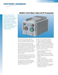
• Host Application Equipment (HAE) IAW<br />
CZE-93-105A-SAASM<br />
Figure 1 – LN-251 features<br />
for motion compensation or stabilization <strong>of</strong> other<br />
sensors such as radar or electro-optic pods. NSD<br />
is also in the process <strong>of</strong> adding differential Global<br />
Positioning System (GPS) correction capability to<br />
provide even further enhancement <strong>of</strong> absolute positional<br />
accuracy. Using this method, radial position<br />
errors have been demonstrated to be only a few 10s<br />
<strong>of</strong> centimeters.<br />
<strong>Fiber</strong>-<strong>Optic</strong> Gyro <strong>Based</strong> INS/GPS for<br />
Military Applications<br />
The LN-251 INS/GPS is the basis <strong>of</strong> NSD’s<br />
family <strong>of</strong> fi ber-optic gyro based navigation grade<br />
inertial systems. The LN-251 resulted from a<br />
DARPA funded project to produce the next generation<br />
<strong>of</strong> navigation grade inertial system that<br />
would provide the smallest volume, lowest weight,<br />
lowest power consumption and highest reliability<br />
system compared to any other approach using alternate<br />
technologies such as mechanical or ring<br />
laser gyros. The features <strong>of</strong> the LN-251 are provided<br />
in Figure 1.<br />
• AE1/GAS-1 antenna interface IAW CI-FRPA-3070<br />
based on current GPS Space & Control<br />
Segment Error<br />
• DS-102 crypto variable load<br />
• PTTI and HaveQuick IAW ICD-GPS-060A<br />
• Zeroize<br />
• RF-FRPA/CRPA antenna interface IAW<br />
CI-FRPA-3070<br />
• DGPS RTCM Type 1/StarFire TM GPS<br />
3
The advances made with this system are due<br />
to the adoption <strong>of</strong> fi ber-optic technology to provide<br />
the angular rate sensing. <strong>Fiber</strong>-optic gyros in<br />
comparison to ring laser gyros require no mechanical<br />
dither for their operation and thus eliminate a<br />
troublesome noise source; do not require high voltage<br />
for the laser plasma, hence reduce power con-<br />
4<br />
OPTICA<br />
OPTICAL L<br />
ICE Card<br />
MECHANICAL<br />
<strong>Optic</strong>s Tray<br />
Figure 2 – <strong>Fiber</strong>-optic gyro architecture in the LN-251<br />
Sensor Cover<br />
Sensor Assembly<br />
Card Cage Cover<br />
Power Supply<br />
SP/AIU Card<br />
Embedded SAASM<br />
GPS Module<br />
Interconnect<br />
Front Panel Card<br />
Front Panel Cover<br />
GPS Battery<br />
Battery Cover<br />
Figure 3 – LN-251 exploded view<br />
sumption; and, with the exception <strong>of</strong> a laser diode<br />
for the light source are composed <strong>of</strong> passive optical<br />
components and thus yield extremely high reliability<br />
compared to any other available technology. The fi -<br />
ber-optic gyro architecture employed in the LN-251<br />
is displayed in Figure 2.<br />
IFOG Assembly <strong>Optic</strong>al Receiver<br />
Card<br />
To minimize volume and power consumption<br />
only a single light source is used to operate all three<br />
fi ber-optic gyro axes. Because the lifetime <strong>of</strong> laser<br />
diodes is rated in millions <strong>of</strong> hours, there is no impact<br />
to the reliability <strong>of</strong> the LN-251 due to failure<br />
modes <strong>of</strong> the light source. This is in strong contrast<br />
to ring laser gyro based systems for which the<br />
system reliability is a strong function <strong>of</strong> the lifetime<br />
and reliability <strong>of</strong> the ring laser gyro.<br />
System Description<br />
The LN-251 INS/GPS is a tightly coupled INS<br />
and GPS system, using Line-<strong>of</strong>-Sight (LOS) from<br />
the GPS to correct navigation parameters and inertial<br />
instrument errors using a Kalman fi lter. Figure 3<br />
shows an exploded view <strong>of</strong> the LN-251 INS/GPS.
The INS/GPS system consists <strong>of</strong> a Miniature <strong>Inertial</strong><br />
Measurement Unit (MIMU), an Embedded GPS<br />
Receiver (ESR), a System Processor/Adaptable Interface<br />
Unit (SP/AIU), a Power Supply (PS), an adaptable<br />
front panel assembly, and a chassis. The ESR pro-<br />
23610 -014<br />
X IFOG<br />
Y IFOG<br />
Z IFOG<br />
<strong>Optic</strong>s<br />
Tray<br />
PD<br />
PD<br />
PD<br />
Instrument Controller<br />
Electronics<br />
2x1 Tap<br />
Coupler<br />
<strong>Optic</strong>al<br />
Receiver<br />
Electronics<br />
Y IFOG<br />
Z IFOG<br />
Pump Diode<br />
Assembly<br />
Pump Monitor<br />
cesses the GPS<br />
satellite signals<br />
and outputs<br />
satellite data<br />
to the system<br />
processor. The<br />
system processor<br />
combines<br />
the GPS data<br />
with the inertial<br />
data from<br />
the MIMU in a tightly coupled GPS/inertial mechanization<br />
using a Kalman fi lter. The INS-aiding data are<br />
also provided to the ESR to aid and pre-position the<br />
GPS tracking loops. The INS/GPS provides three simultaneous<br />
navigation solutions: a hybrid INS/GPS<br />
navigation solution, an INS-only navigation solution,<br />
and a GPS-only navigation solution.<br />
All required functions are provided in a compact<br />
implementation. The functional partitioning is illustrated<br />
in Figure 4 and shows the ESR, MIMU, and<br />
SP/AIU functions.<br />
The MIMU, as shown in Figure 5, provides precision<br />
measurements <strong>of</strong> acceleration and rotation. The<br />
integrated navigation function provides corrections to<br />
these measurements. The MIMU consists <strong>of</strong> a sensor<br />
assembly comprising three interferometric fi ber-optic<br />
gyroscopes, three accelerometers, and an instrument<br />
controller electronics assembly. The inertial instruments<br />
are mounted on an ISO inertial, rugged vibration-isolated<br />
sensor block.<br />
MIOC Drive<br />
Electronics<br />
Instrument<br />
Controller ASIC<br />
BFS Source<br />
Electronics<br />
3x Accel<br />
Figure 4 – Functional partitioning <strong>of</strong> LN-251 equipment<br />
Figure 5 – Miniature <strong>Inertial</strong><br />
Measurement Unit<br />
The ESR is a 12-channel all-in-view GPS receiver.<br />
In addition to the Pseudo-Range (PR) and Delta Range<br />
(DR) data, the ESR provides the standard set <strong>of</strong> position,<br />
velocity, and time (PVT) data. Receiver Autonomous<br />
Integrity Monitor (RAIM) and Fault Detection<br />
and Exclusion (FDE) calculations and annunciations,<br />
in accordance with DO-229, are included.<br />
S<strong>of</strong>tware<br />
+3.3V<br />
+5.2V<br />
±6.25V<br />
±12.5V<br />
+27V<br />
SP/AIU<br />
ESR<br />
Power<br />
Supply<br />
I/O<br />
Antenna<br />
ESR I/O<br />
28 Vdc<br />
The system processor Computer S<strong>of</strong>tware Confi<br />
guration Item (CSCI) is modular for proper control,<br />
ease <strong>of</strong> maintenance, and straightforward adaptability<br />
to new applications without complex modifi cations.<br />
The s<strong>of</strong>tware is programmed in Ada and executes on<br />
the PowerPC TM microprocessor. The SP/AIU CSCI<br />
performs four main functions: MIMU processing,<br />
navigation processing, integrity processing, and application<br />
processing.<br />
The system processor CSCI compensates gyro<br />
and accelerometer data for temperature and other effects<br />
using calibration data. Body frame incremental<br />
velocity and angle data are produced. The gyro secondary<br />
control loops are closed and monitored for<br />
optimal performance.<br />
The system processor CSCI computes a naviga-<br />
5
tion solution for host vehicle position and velocity<br />
using incremental velocity and angle data from the<br />
MIMU processing. A Kalman fi lter uses GPS measurement<br />
data, baro altitude, and external reference<br />
data to estimate and correct errors in the navigation<br />
solution, in host vehicle attitude, and in inertial sensor<br />
outputs. The system processor uses its navigation<br />
solution, position, and velocity data to compute<br />
inertial aiding data to be used by the GPS tracking<br />
loops.<br />
Alignment modes include stationary and moving<br />
based alignments. Moving based alignments<br />
support GPS and external Position/Velocity aiding.<br />
The INS/GPS will provide on-deck GPS aided carrier<br />
alignment capability. Independent navigation<br />
modes <strong>of</strong> INS-only, GPS-only, and hybrid (INS/<br />
GPS) are provided. Built-in-Test (BIT) provides<br />
start-up (SBIT), periodic (PBIT) and commanded<br />
test (IBIT) modes<br />
Performance<br />
The inertial navigation solution is bounded over<br />
long periods <strong>of</strong> time by the GPS, and the long-term<br />
system position, velocity and time (PVT) accuracy is<br />
limited by the errors in the GPS system. High frequency<br />
errors (defi ned as errors which have a correlation<br />
time signifi cantly less than a Schuler period)<br />
are largely driven by the noise characteristics <strong>of</strong> the<br />
inertial instruments and white noise in the GPS<br />
measurements. The INS/GPS Kalman navigation<br />
fi lter contains states that estimate and compensate<br />
for modelable errors in the inertial instruments and<br />
GPS system. By nature these modelable errors tend<br />
to have relatively long correlation times. The navigation<br />
performance <strong>of</strong> the LN-251 is summarized in<br />
Figure 1.<br />
Land <strong>Navigation</strong><br />
The LN-270 INS/GPS system is the land production<br />
confi guration <strong>of</strong> the LN-251 INS/GPS.<br />
NSD is currently delivering production LN-270<br />
systems for an international howitzer program. The<br />
difference between the LN-270 and LN-251 is in<br />
the application table-driver s<strong>of</strong>tware. The LN-270<br />
includes provisions to interface to a land vehicle<br />
Velocity Measurement System (VMS), such as the<br />
standard MIL-PRF-71196 odometer. The LN-270<br />
6<br />
Figure 6 – NSD’s LN-<br />
270 for land navigation<br />
applications<br />
GPS/INS provides<br />
the level <strong>of</strong> performance<br />
necessary<br />
to achieve 1 mil<br />
azimuth accuracy at<br />
75 degrees latitude<br />
(north or south).<br />
The same airborne<br />
GPS receiver found<br />
in the LN-251 is embedded<br />
in the LN-<br />
270 forming a tight-<br />
ly-coupled INS/GPS suitable for all land navigation<br />
applications. The LN-270 is pictured in Figure 6.<br />
Aircraft Retr<strong>of</strong>i t Applications<br />
Not all aircraft applications can take advantage<br />
<strong>of</strong> the LN-251 features, particularly in retr<strong>of</strong>i t applications<br />
due to the expense <strong>of</strong> aircraft modifi cation<br />
that might be required. For these situations,<br />
NSD has developed the LN-260 which combines<br />
the features <strong>of</strong> the LN-100 including missionization<br />
s<strong>of</strong>tware and input/output (I/O) protocol with the<br />
benefi ts <strong>of</strong> the FOG sensor assembly.<br />
The LN-260 provides:<br />
• Increased operating life, based on the FOG LN-<br />
251 inertial sensor<br />
• More than double the reliability <strong>of</strong> Ring Laser<br />
Gyro (RLG) based designs<br />
• Commonality with the F-16, SNU 84 interfaces<br />
• Growth to include CNS/ATM GATM requirements<br />
• Enhanced INS performance, required to maximize<br />
the surveillance sensor performance<br />
The LN-260 represents the state-<strong>of</strong>-the-art in<br />
aircraft navigation. The fi rst application for the LN-<br />
260 will be in the recently awarded F-16 upgrade application.<br />
The LN-260 is pictured in Figure 7. The<br />
sensor assembly is identical with that used in the<br />
LN-251 while the I/O and missionization has been<br />
sourced from the performance-proven <strong>Northrop</strong><br />
Grumman LN-100 product line.
Figure 7 – LN-260 showing LN-251<br />
sensor assembly<br />
Two LN-260 INS/GPS prototypes recently<br />
completed fl ight testing in a high dynamic fi ghter<br />
aircraft environment to demonstrate the maturity<br />
<strong>of</strong> the fi ber-optic gyro technology and the<br />
capabilities <strong>of</strong> the LN-260 system. A typical<br />
fl ight trajectory is shown in Figure 8.<br />
CD15 Flight #<br />
/ Date<br />
Specification<br />
1539 / 7-1-05<br />
1542 / 7-12-05<br />
1543 / 7-13-05<br />
1545 / 7-15-05<br />
1598 / 9-14-05<br />
1599 / 9-14-05<br />
Total<br />
RMS/CEP<br />
V North<br />
Error<br />
(Ft/Sec RMS)<br />
< 2.5 F/S<br />
RMS<br />
3.51<br />
0.98 / 1.08<br />
0.85 / 0.92<br />
1.48 / 1.50<br />
1.47<br />
1.57<br />
1.86<br />
< 2.5 F/S<br />
RMS<br />
2.37<br />
0.44 / 0.49<br />
1.18 / 1.19<br />
3.36 / 3.49<br />
2.86<br />
2.97<br />
2.43<br />
Figure 8 – Typical fl ight trajectory for LN-260 testing<br />
A total <strong>of</strong> nine test fl ights were performed with seven<br />
<strong>of</strong> those fl ights including maneuvers in excess <strong>of</strong> 9 g. The<br />
results <strong>of</strong> the fl ight tests are displayed in Table 1.<br />
V East<br />
Error<br />
(Ft/Sec<br />
RMS)<br />
RER<br />
(NMi/Hr)<br />
< 0.8 @ 50%<br />
CEP<br />
0.44<br />
0.17 / 0.16<br />
0.28 / 0.23<br />
0.73 / 0.59<br />
0.60<br />
0.93<br />
0.49<br />
Comments<br />
PROD 2, High Dynamics,<br />
No TPSI<br />
PROD 2, Medium<br />
Dynamics, TPSI<br />
PROD 2, High Dynamics,<br />
TPSI<br />
PROD 2, High Dynamics,<br />
TPSI<br />
PROD 4, Medium<br />
Dynamics, No TPSI<br />
PROD 4, High Dynamics,<br />
No TPSI<br />
Table 1 – Summary <strong>of</strong> fl ight test results for the LN-260 in high dynamic environment<br />
Table 1 clearly shows that the LN-260 meets or exceeds the SNU-84 requirements.<br />
7
Commercial Applications<br />
NSD is also bringing the advantages <strong>of</strong> fi beroptic<br />
gyro technology to the commercial aircraft<br />
navigation market with the LTN-101E <strong>Inertial</strong><br />
Reference System. Of extreme importance in this<br />
market is the very high reliability and long life that<br />
fi ber-optics technology brings compared to current<br />
ring laser gyro technology. The LTN-101E provides<br />
highly reliable velocity and attitude information<br />
for the aircraft. The LTN-101E subassemblies are<br />
shown in Figure 9.<br />
The system is composed <strong>of</strong> the sensor assembly,<br />
power supply, HIRF/Lightning module, processor,<br />
air data, and the module that mixes with the external<br />
GPS inertial data. The LTN-101E sensor assembly<br />
uses the same fi ber-optic gyro technology as the<br />
LN-251; however, the gyros are screened specifi -<br />
cally for the export market and mounted on a sensor<br />
block that precludes the use <strong>of</strong> the LTN-101E<br />
in high dynamic military applications.<br />
Future Improvements<br />
The geolocation problem is pushing the requirements<br />
for positional accuracies. NSD has been investigating<br />
the use <strong>of</strong> differential GPS corrections<br />
8<br />
Figure 9 – LTN-101E Subassemblies<br />
in the LN-251 and LN-260 to provide the user with<br />
the most accurate positional information possible.<br />
DGPS is the process in which corrections are applied<br />
to the GPS signal to compensate errors in the<br />
broadcast GPS signal. These errors are composed<br />
<strong>of</strong> errors in the knowledge <strong>of</strong> the position <strong>of</strong> the<br />
GPS satellite and errors in the satellites, onboard<br />
clock, as well as atmospheric disturbances that corrupt<br />
the GPS signal in the local area. In the standard<br />
operation <strong>of</strong> GPS, the receiver derives positional<br />
information by interpreting the timing data on the<br />
signal and the broadcast location <strong>of</strong> the satellite. In<br />
differential GPS, the differential reference receiver<br />
knows its location very precisely and thus can invert<br />
the normal process and derive equivalent timing<br />
errors on the signal by comparing the known and<br />
derived locations. These timing errors are a result<br />
<strong>of</strong> dynamic conditions in the ionosphere which can<br />
change quite rapidly as well as errors in the GPS<br />
satellite clock and orbit information which change<br />
quite slowly. Accordingly these errors have to be<br />
continuously derived and provided back to the roving<br />
GPS receiver to compensate for errors created<br />
by the atmospheric conditions, both in the ionosphere<br />
and the troposphere and satellite errors. In<br />
the most simple <strong>of</strong> DGPS approaches the errors<br />
are treated as a lump sum whereas in the more so-
phisticated approaches attempts are made to separate<br />
out the satellite position, satellite clock, ionosphere<br />
and troposphere propagation errors and handle them<br />
individually. Applying differential GPS corrections<br />
can reduce positional errors to achieve sub-meter<br />
accuracies.<br />
NSD has demonstrated the improvements in<br />
position accuracies available in the LN-251 using<br />
the DGPS corrections available from the StarFire TM<br />
subscription service, available from NavCom <strong>of</strong><br />
Torrance, California.<br />
Figures 9a and 9b show almost an order <strong>of</strong> magnitude<br />
improvement in position accuracy with the<br />
StarFire TM corrections as compared to using only the<br />
GPS signal.<br />
Figure 9a depicts the distribution <strong>of</strong> position as<br />
computed from the INS/GPS solution over a 24 hour<br />
period in which the differential corrections available<br />
from the StarFire TM system were employed resulted<br />
in an rms value <strong>of</strong> less than 40 cm. Figure 9b shows<br />
the same 24 hour period, however in this case only<br />
the INS/GPS hybrid solution was computed without<br />
the differential GPS corrections. The rms positional<br />
accuracy is this case was about 3 m.<br />
Surveillance Sensor Enhancement<br />
Precision surveillance and geolocation requires accurate<br />
attitude and velocity information from the<br />
sensor itself. It is not suffi cient to have only the<br />
navigation solution for the platform since the attitude<br />
<strong>of</strong> the sensor can be independent <strong>of</strong> the host<br />
platform. Mounting a navigation grade INS/GPS<br />
to the surveillance sensor would be an ideal solution<br />
from a precision and accuracy point <strong>of</strong> view but is<br />
typically not practical due to the size, weight and<br />
power dissipation <strong>of</strong> the inertial unit, which would<br />
adversely affect the performance <strong>of</strong> the surveillance<br />
sensor. An alternate approach is to employ a small,<br />
Figures 9a and 9b – Positional accuracies with and without the differential GPS corrections<br />
lightweight and low power inertial measurement unit<br />
(IMU) on the sensor and then mechanize a transfer<br />
alignment from the navigation grade INS/GPS on<br />
the platform to the IMU on the sensor.<br />
The LN-251 enhances this transfer alignment<br />
due to the low noise characteristics <strong>of</strong> the FOG<br />
technology. Unlike standard ring laser gyros, which<br />
employ a dither motor to eliminate the lock-in effect,<br />
the fi ber-optic gyro does not need mechanical<br />
dither and thus does not inject extraneous noise into<br />
the process. This is very important when mechanizing<br />
a velocity-matching algorithm in the transfer<br />
alignment process. Velocity matching is clearly<br />
the desired approach for Synthetic Aperature Radar<br />
(SAR) applications because any uncertainty or noise<br />
in the velocity estimates will result in blurring <strong>of</strong> the<br />
SAR imagery.<br />
To demonstrate the advantages <strong>of</strong> the LN-251<br />
in the SAR application, a series <strong>of</strong> test fl ights were<br />
conducted using a Sabreliner aircraft and <strong>Northrop</strong><br />
Grumman’s APG-68 fi re control radar in the SAR<br />
9
Figure 10a – Sabreliner aircraft used for<br />
fl ight tests<br />
Figure 10b – LN-251 Mounted in front electronics<br />
bay <strong>of</strong> the Sabreliner<br />
mode. The LN-251 provided the master INS data.<br />
The APG-68 used NSD’s LN-200, a fi ber-optic<br />
gyro IMU mounted directly on the radar unit for basic<br />
stabilization. A velocity matching transfer alignment<br />
mechanization was implemented between the<br />
LN-251 and the LN-200. The setup for these fl ight<br />
tests is shown in Figures 10 a – c.<br />
The results <strong>of</strong> 188 SAR maps are summarized<br />
in Table 2, showing velocity accuracies over the ensemble<br />
<strong>of</strong> fl ights are less than 0.05 ft/sec.<br />
Target location errors derived from these tests<br />
showed average error in the range <strong>of</strong> 4 ft with a<br />
standard deviation <strong>of</strong> 2 ft and average azimuth error<br />
<strong>of</strong> 13 ft with a standard deviation <strong>of</strong> 8 ft.<br />
Summary<br />
<strong>Northrop</strong> Grumman’s <strong>Navigation</strong> System Division<br />
has introduced a family <strong>of</strong> fi ber-optic gyro based<br />
inertial navigation systems to fulfi ll a large variety <strong>of</strong><br />
10<br />
Figure 10c – LN-200 IMU mounted on the<br />
APG-68 Radar<br />
FLT<br />
213<br />
231-<br />
234<br />
Sample<br />
Size<br />
(# <strong>of</strong><br />
Maps)<br />
40<br />
148<br />
Mean<br />
0.019<br />
0.016<br />
Velocity Error<br />
(fps)<br />
Std<br />
0.023<br />
0.041<br />
Rms<br />
0.029<br />
0.044<br />
Table 2 – Average Velocity Error over series <strong>of</strong><br />
SAR fl ight tests<br />
applications. The introduction <strong>of</strong> fi ber-optic gyro<br />
technology in these applications has resulted in systems<br />
<strong>of</strong> superb reliability that are ideally suited for<br />
the geolocation and surveillance sensor applications<br />
as well as military and commercial aircraft and land<br />
navigation.
Strategic Programs & Business<br />
Development (SP&BD),<br />
<strong>Navigation</strong> Systems Division<br />
One <strong>of</strong> the main functions <strong>of</strong> the SP&BD organization<br />
is to sustain NSD’s competitive advantage in all<br />
<strong>of</strong> its product lines by providing cutting edge technologies<br />
that supply entirely new capabilities to the<br />
marketplace and also enhance its current products.<br />
Ike J. Song, Director <strong>of</strong> SP&BD<br />
ike.song@ngc.com<br />
For more information, please contact:<br />
<strong>Northrop</strong> Grumman Corporation<br />
<strong>Navigation</strong> Systems<br />
21240 Burbank Boulevard<br />
Woodland Hills, CA 91367 USA<br />
1-866-NGNAVSYS (646-2879)<br />
www.nsd.es.northropgrumman.com