Design and Implementation of HW-SW System for ... - Institut AIFB
Design and Implementation of HW-SW System for ... - Institut AIFB
Design and Implementation of HW-SW System for ... - Institut AIFB

Create successful ePaper yourself
Turn your PDF publications into a flip-book with our unique Google optimized e-Paper software.
Core <strong>of</strong> the system are 2 Analog Devices AD7730 high resolution A/D converters. This<br />
bridge transducer A/D converter has specifications that match very well with the requirements<br />
<strong>for</strong> the application <strong>of</strong> <strong>for</strong>ce measurement using <strong>for</strong>ce sensors <strong>for</strong>med as Wheatstone bridges.<br />
The features <strong>of</strong> AD7730 will be discussed in depth in following chapters.<br />
Sensors have strain gage transducers whose resistance changes when subjected to mechanical<br />
stress. The gages are configured in a Wheatstone bridge arrangement, <strong>and</strong> they are passive<br />
devices <strong>and</strong> require an excitation voltage to generate a voltage output. The block “Reference<br />
Voltage Source” in Figure 1 supplies the sensor with the high precision reference voltage <strong>for</strong><br />
exciting the bridge. It is possible to choose between 2.5V <strong>and</strong> 5V reference voltage. First one<br />
is obtained using Analog Devices AD580 component that supplies 2.5V±0.4%, <strong>and</strong> the later<br />
one with Analog Devices high precision AD586 device that supplies 5V±0.04%. It is also<br />
possible to use system 5V supply voltage as a reference voltage, or to connect external<br />
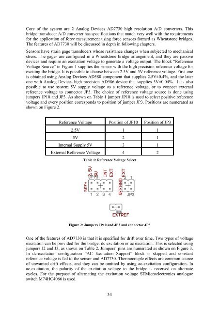
reference voltage to connector JP5. The choice <strong>of</strong> reference voltage source is done using<br />
jumpers JP10 <strong>and</strong> JP3. As shown on Table 1 jumper JP10 is used to select positive reference<br />
voltage <strong>and</strong> every position corresponds to position <strong>of</strong> jumper JP3. Positions are numerated as<br />
shown on Figure 2.<br />
Reference Voltage Position <strong>of</strong> JP10 Position <strong>of</strong> JP3<br />
2.5V 1 1<br />
5V 2 1<br />
Internal Supply 5V 3 1<br />
External Reference Voltage 4 2<br />
Table 1: Reference Voltage Select<br />
Figure 2: Jumpers JP10 <strong>and</strong> JP3 <strong>and</strong> connector JP5<br />
One <strong>of</strong> the features <strong>of</strong> AD7730 is that it is specified <strong>for</strong> drift over time. Two types <strong>of</strong> voltage<br />
excitation can be provided <strong>for</strong> the bridge: dc excitation or ac excitation. This is selected using<br />
jumpers J2 <strong>and</strong> J3, as shown on Table 2. Jumpers’ pins are numerated as shown on Figure 3.<br />
In dc-excitation configuration “AC Excitation Support” block is skipped <strong>and</strong> constant<br />
reference voltage is fed to the sensor <strong>and</strong> AD7730. Thermocouple effects are common source<br />
<strong>of</strong> unwanted drift effects, <strong>and</strong> they can be omitted by using ac-excitation configuration. In<br />
ac-excitation, the polarity <strong>of</strong> the excitation voltage to the bridge is reversed on alternate<br />
cycles. For the purpose <strong>of</strong> alternating the excitation voltage STMicroelectronics analogue<br />
switch M74HC4066 is used.<br />
34