View PDF - Canadian Consulting Engineer
View PDF - Canadian Consulting Engineer
View PDF - Canadian Consulting Engineer
You also want an ePaper? Increase the reach of your titles
YUMPU automatically turns print PDFs into web optimized ePapers that Google loves.
CANADIAN CONSULTING<br />
ENGINEERING AWARDS 2012<br />
Association of <strong>Consulting</strong> <strong>Engineer</strong>ing Companies Canada<br />
<strong>Canadian</strong> <strong>Consulting</strong> <strong>Engineer</strong><br />
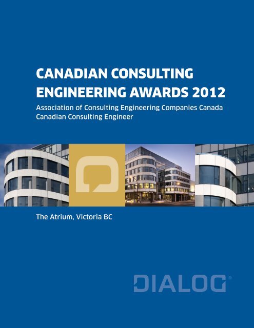
The Atrium, Victoria BC
“<br />
W. Arthur Porter<br />
The innovation point is the pivotal moment when<br />
talented and motivated people seek the opportunity<br />
to act on their ideas and dreams.
CONTENTS<br />
a. Confirmation Receipt from Official Entry Form<br />
b. Entry Consent Form<br />
c. 2-Page Project Highlights<br />
d. Full Project Description
aconfirmation receipt from official entry form
c2-page project highlights
The Atrium<br />
The Atrium building located in Victoria, British Columbia is close to 18,600 m2 of office and commercial/retail<br />
space in a seven-storey structure. The building’s high efficiency envelope utilizes Ultra-High Performance Concrete<br />
(UHPC) spandrel panels in its exterior wall cladding. The project required a sustainable facade solution that<br />
reflects the vibrant nature of Downtown Victoria. This was reflected in the facade design through the owner’s and<br />
architect’s desire to have irregular surface textured panels that can also form tight radial curves at the building<br />
corners. These requirements were met through careful use of UHPC; a material that has been available since the<br />
mid-90’s (especially in Europe) and over the past decade has been gaining popularity in North America, mostly in<br />
bridge construction. The Atrium is the first building in North America to have a UHPC façade.<br />
For building facades, architects, building officials and owners traditionally prefer natural materials such as stone<br />
and granite or manmade brick and concrete block. All these materials are capable of supporting compressive loads<br />
but have limited resistance to loads that cause bending. They are also not suitable for producing curved shapes.<br />
Introducing irregular surface texture on cladding panels made of such materials would have been possible but<br />
not practical and would be labour intensive, and extremely costly. Metal panels could be used to produce curved<br />
shapes but are not suitable for forming tight radial curves and cannot have irregular textured surface.<br />
UHPC’s flowability, mouldability and self-consolidation characteristics allowed recalling the appearance of<br />
handcrafted brick and stone in Victoria’s historic buildings. Understanding UHPC’s characteristics along with<br />
innovative structural design and construction techniques resulted in customized design and creation of highly<br />
durable, attractive, ultra-thin (17 mm) UHPC cladding panels for The Atrium’s unitized curtain wall system. This<br />
unique project involved close collaboration between panel designer - DIALOG and precast manufacturer / UHPC<br />
material supplier - Lafarge Canada. The characteristics of UHPC; very high compressive strengths (up to 250 MPa)<br />
associated with excellent ductility, improved flexural behaviour and tensile properties - in addition to its superior<br />
durability characteristics, made UHPC the logical choice for use in The Atrium’s cladding panels. Non-metal panels<br />
would have resulted in panels about four to five times thicker and heavier than UHPC panels. Additionally, since<br />
the project is located in one of the highest rating seismic zones in Canada, the heavier panels penalize natural<br />
products.<br />
Manufacturing at Lafarge’s precast facility in Calgary involved casting a total of 690 panels of flat and curved<br />
panels. The surface texture on the panels was replicated from the architect’s own hand-scored pattern on a master<br />
mould. Due to limited use of the material in cladding applications, surface coating that facilitates removal of any<br />
accidental stains was used as manufacturers and architects are still experimenting with surface finishes.<br />
Even though the decision was made that UHPC was the logical material for use in the project, we were faced with<br />
the fact that there are no design standards, codes of practice and/or guideline specifications available in North<br />
America for implementation of UHPC in structural applications. In addition most UHPC proven mixes utilize steel<br />
fibres, which greatly influence the material characteristics and performance. Presence of steel fibres would have<br />
resulted in unsightly rust stains on the face of the panels. Replication of the handcrafted surface texture (irregular<br />
wavy face ribs) and formation of tight radial curved panels were some of the other challenges. Connections of<br />
the panels to the support frame in the curtain wall were also a major concern and required simplification to<br />
accommodate construction and performance tolerances.<br />
To overcome the technical challenges, a state of the art review of UHPC in structural applications was carried out<br />
and the structural design had to rely on first principles along with finite element computer models to predict the<br />
structural behaviour. A UHPC mix with polyvinyl alcohol (PVA) fibres was used and new material law (stress-strain<br />
curve) that allows prediction of the material behaviour had to be developed. Finally, the structural design of the<br />
panels had to be validated through full scale load testing at an independent laboratory. DIALOG had to develop the<br />
test program and design a testing frame that utilizes air mattresses for uniform load application. Other load tests<br />
were carried out after the preliminary engineering stage to arrive at the support anchor capacities and coordinate<br />
the support requirements with the curtain wall and building designers.
The Atrium<br />
Unlike other sustainable construction projects that are usually assessed based on the environmental impact of the<br />
employed materials at the time of their production and construction, in The Atrium the importance of sustainable<br />
construction and life cycle was realized and the goal was to achieve a balance between the initial cost and the life<br />
cycle - keeping in mind that some natural materials have low environmental impact at the time of production but<br />
have a short-term life expectancy and that concrete, the most common manmade building material on the planet<br />
and a source of industrial emissions (mostly from cement production), minimizing the quantities of concrete as<br />
proven by the ultra-thin panels in The Atrium is a step in the right direction.<br />
The ultra-thin panels directly minimized weight of the building exterior walls and consequently resulted in<br />
reduced initial cost (UHPC is costly in comparison with normal or high performance concrete), reduced earthquake<br />
forces on the support structure, and in ease of assembly into the unitized curtain wall system. Conventional<br />
precast panels would have involved swinging large, heavy panels through the air to pin them on a previously<br />
erected wall system. This process was eliminated since the panels were preassembled into the wall system.<br />
The design maximized panel dimensions to limit the number of joints between the panels and reduced the<br />
number of bridging components to obtain a high energy efficient building envelope with smaller wall thickness<br />
in comparison with conventional walls. UHPC allowed freedom to form monolithically tight radial curves instead<br />
of smaller, segmented flat panels which would have created more seams and openings in the facade - potentially<br />
reducing the building’s energy efficiency. In addition, use of a white color UHPC mix enhanced the energy<br />
efficiencies and facilitated reflection of the sun’s heat energy to reduce the cooling load.<br />
From the early stages of the project, through to completion, it was important to establish and maintain an open,<br />
collaborative team approach, with a high level of trust (between the owner, architect, developer and fabricator) in<br />
order to complete prototyping, obtain approvals and avoid delays or problems with the project schedule, which<br />
was met.<br />
Recent developments in construction materials technology, combined with the aspiration of the construction<br />
industry to provide sustainable solutions, has resulted in completion of The Atrium; the first building in North<br />
America to utilize UHPC cladding panels as thin as 17 mm. The Atrium project adds to the current state of<br />
knowledge and encourages use of advanced construction materials to meet the sustainability goals for the future.<br />
UHPC is gaining popularity for use in construction in comparison with other advanced materials such as fibre<br />
reinforcing polymer (FRP) bars that have been available for more than two decades but their use in construction<br />
is still limited as such bars cannot be used as direct replacement to steel reinforcement. Many engineering<br />
organizations are exploring adopting the material and developing engineering standards and specifications for its<br />
use in structural applications. The design and testing results of the Atrium panels will be used by members of the<br />
“North American UHPC User’s Group”, formed in 2010 by a group of professional volunteers and by the recently<br />
formed (Fall 2011) ACI Committee 239 who’s mandate is to develop a UHPC material design guidelines and<br />
specifications suitable for use in North America.<br />
Use of UHPC in cladding applications will positively impact the building and construction industries as it responds<br />
to the Architects’ creative designs and expectations with unlimited demands on shape and form, the Structural<br />
<strong>Engineer</strong>s’ ambitions for providing safe, durable and maintenance free structures, the Precaster/Erector’s concerns<br />
for ease of construction, the Contractor’s demands for economical designs that can be constructed efficiently and<br />
safely in a timely manner, and above all the Owner’s aspiration for attractive, “Green”, safe, operable, economical<br />
and profitable (including life cycle costs) buildings. The successful application of UHPC in architectural cladding,<br />
as demonstrated by The Atrium project, is expected to lead the way towards utilization of similar panels in future<br />
building facades and to efficiently utilize UHPC material properties in architectural design. The result will be<br />
long-lasting structures that require less materials and unique designs with ultra-thin panels, complex forms,<br />
texture and shapes.
dfull project description<br />
DETAIL 1
introduction<br />
The Atrium Building in Victoria, British Columbia is close to 18,600<br />
sq m (200,000 sq ft) public space. The building is a seven-storey<br />
structure with an open atrium at its centre and has a large skylight<br />
that allows natural daylight into the interior of the building. The<br />
project is targeted to achieve LEED® Gold rating through the<br />
Canada Green Building Council. One of the major elements in this<br />
consideration is the building’s high efficiency envelope that utilizes<br />
Ultra-High Performance Concrete (UHPC) spandrel panels designed<br />
to be as thin as possible.<br />
DETAIL 2<br />
“<br />
Theodore Levitt<br />
Just as energy is the basis of life itself, and ideas the<br />
source of innovation, so is innovation the vital spark<br />
of all human change, improvement and progress.<br />
DETAIL 6<br />
1x
Fig. 1 – Atrium Victoria
Vision and Scope<br />
To reflect the vibrant nature of Downtown Victoria and nearby waters, the building<br />
architect (D’Ambrosio Architecture + Urbanism) desired to create surface texture on the<br />
panels as that shown in Figure 2, and to have curved panels at the building corners.<br />
The surface texture recalls the handcrafted brick and stone found in many of Victoria’s<br />
historic buildings. DIALOG’s scope in the project was limited to the structural design<br />
and engineering of the panels in accordance with BC Building code and to provide<br />
design forces and recommendation for supporting the panels as part of the curtain<br />
wall. Lafarge’s scope was the supply of the UHPC material and the manufacturing of the<br />
precast panels for assembly in the curtain wall at an offsite facility.<br />
Panel Geometry<br />
The façade design utilized 690 precast panels with different plan geometry; flat, curved<br />
and partially curved. All panels were 1300 mm high and varied in width from 750 to<br />
2150 mm (majority) 1300 mm wide. The building layout at levels 2 to 5 is depicted<br />
in Figure 3 and typical panel geometry and shape is depicted in Figure 4. The surface<br />
texture or face ribs are roughly 5mm deep and vary in width from 10 to 20 mm and<br />
are 10-20 mm apart in irregular form as shown in Figure 2.<br />
Fig. 2 – Surface Texture Fig. 3 – Level 205 Plan Layout
Fig. 5.1 – UHPC Panels Forming Curved Corners<br />
Figure 5.2 Faceted Granite Façade, Husky Oil Tower, Calgary (DIALOG project)
Figure 2 Surface Texture<br />
Varies - MAX. LENGTH = 1450<br />
35mm<br />
35mm<br />
Figure 3 Level 2-5 Plan Layout<br />
Varies - MAX. LENGTH = 1450<br />
20mm<br />
35mm<br />
Fig. 4 – Typical Figure Panel 4 Typical Elevation Panel Elevation and Side Side <strong>View</strong> <strong>View</strong><br />
35mm<br />
Figure 3 Level 2-5 Plan Layout<br />
20mm<br />
Figure 2 A Surface stone Texture<br />
The<br />
or granite<br />
average<br />
panel<br />
designed<br />
of the same<br />
panel<br />
dimensions<br />
thickness<br />
would have been four to five times heavier and much thicker, due to lack<br />
of tensile resistance of such materials. In addition, the Figure curved 4 of Typical 20mm<br />
panels Panel would Elevation allowed<br />
have Side required <strong>View</strong> a fabrication tolerance of 3mm<br />
assembling multi segments<br />
of straight for apanels minimum with complicated structural backing thickness frames or cutting of 17mm. the curved This shapes thickness from thicker was stone used or granite for majority<br />
blocks,<br />
resulting in material wastage and extra cost. Casting the concrete in pre-shaped moulds had the advantage of providing<br />
of<br />
any required A the stone panels<br />
shape or economically granite that panel were of in addition the 1300 same to dimensions mm wide.<br />
the ability to would The<br />
produce have thickness<br />
the been required four to of<br />
surface five the times panels<br />
texture. heavier varied<br />
Use and of metal much slightly<br />
panels thicker, due to lack<br />
would depending have of tensile provided resistance on the the curved of width such shape materials. and andwould plan In have addition, shape. been the lighter Perimeter curved than panels UHPC thickened would panels have but required would edges not assembling on have the provided back multi the segments face of<br />
required surface of straight texture panels with with the complicated ribbing effect backing (Figure frames 2), nor or similar cutting performances the curved shapes against from impact, thicker security, stone or fires granite and blocks,<br />
aesthetics.<br />
theresulting panels<br />
The final in were material appearance<br />
used wastage around<br />
toand encompass<br />
one extra of the cost. curved Casting the<br />
areas<br />
support the of concrete the building<br />
inserts in pre-shaped is shown<br />
and<br />
in<br />
allow moulds Figure had proper<br />
5.1, the with advantage extremely<br />
sealingof of providing the<br />
smooth vertical curves any required formed joints shape by between the economically precast panels thein panels addition -even though to asthe well that ability was asto the disturbed produce horizontal the by the required flat joints glass surface and between texture. zinc panels. Use the of An metal UHPC panels<br />
example would of a building have provided with conventional the curved curved shape façade and would is shown have been in Figure lighter 5.2 than depicting UHPC the panels faceted but would appearance not have and provided the<br />
increased panels required number and surface of joints. thetexture zinc and with the glass ribbing panels effect (Figure that are 2), nor part similar ofperformances the wall assembly. against impact, Panels security, up fires toand<br />
1450<br />
aesthetics.<br />
mm width<br />
The final<br />
were<br />
appearance<br />
supported<br />
around one<br />
at<br />
of<br />
four<br />
the curved<br />
locations<br />
areas of<br />
and<br />
the building<br />
wider<br />
is<br />
ones<br />
shown<br />
at<br />
in Figure<br />
six locations<br />
5.1, with extremely<br />
with<br />
smooth curves formed by the precast panels -even though that was disturbed by the flat glass and zinc panels. An<br />
a mid-height example of a building back with rib conventional added. Additional curved façade inserts is shown located in Figure 5.2 30depicting mm from the faceted the top appearance and bottom and<br />
increased number of joints.<br />
edges of the panel are used for attachment of the zinc and glass panels.<br />
A stone or granite panel of the same dimensions would have been much thicker and<br />
four to five times heavier than the designed UHPC panels. This is due to lack of tensile<br />
resistance of such materials. In addition curved panels would have required assembling<br />
multi segments of straight panels with complicated backing frames or cutting the<br />
curved shapes from thicker stone or granite blocks, which would have resulted in<br />
material wastage and extra cost. Casting the concrete in pre-shaped moulds had the<br />
advantage of providing any desired shape in addition to the ability to economically<br />
produce the required surface texture. Use of metal panels would have provided the<br />
curved shape and would have been lighter than UHPC panels but would not have<br />
provided the required surface texture with the ribbing surface texture depicted in<br />
Figure 2. The final appearance around one of the curved corners of the building (Figure<br />
5) depicts extremely smooth curves formed by the precast panels even though that was<br />
disturbed by the flat or chorded appearance of the glass and zinc panels.
Panel Design<br />
The panels in their final position support their self weight in the plane of the wall as<br />
well as wind loads acting out of plane or perpendicular to the wall. The panels also<br />
transmit seismic forces that act in any direction to the backing frame. In addition due<br />
to the different thicknesses within the panel and the configuration of the thickened<br />
portions of the panels (face and back ribs) in-plane forces develop from the arching<br />
action. To minimize such forces and have the panels behave as close as possible to a<br />
statically determinate elements, the CPCI Design Manual (2007) guidelines for design<br />
of precast panel connections were used in obtaining the support boundary conditions,<br />
refer to Figure 6. These boundary conditions were used in the structural analysis of<br />
the panels to permit accurate determination of force distribution and minimize internal<br />
stresses. It also permitted movements in the plane of the panel to accommodate<br />
temperature effects. The expected movement was accommodated in the support angles<br />
that are part of the backing frame and were designed by others.<br />
Fig. 6 – Typical Connection Arrangement (CPCI Design Manual, 2007)<br />
Wind loads on the panels were calculated in accordance with the 2005 National<br />
Building Code of Canada and checked against the 2006 British Columbia Building<br />
Code. The net wind suction and pressure loads including internal pressure effects at<br />
the corner or end zones of the building were 1.91 kPa and 1.54 kPa, respectively. As<br />
the panel thicknesses were quite small, seismic loads which are function of the panel<br />
weight were not critical.
Design Challenges<br />
Close collaboration between DIALOG and Lafarge was crucial for the successful design<br />
of the panels. UHPC material properties were investigated for many UHPC mixes,<br />
especially that no steel fibres were allowed in the mix to avoid rust stains on the<br />
surface. In addition, the desire to have panels with as light a colour as possible to<br />
reflect sunlight and reduce cooling loads, played a major role in tailoring a suitable<br />
UHPC mix. Different UHPC mixes were investigated and tested by Lafarge until a<br />
suitable mix with Polyvinyl Alcohol Fibres (PVA) was engineered. A new material law<br />
(stress-strain curve) that depicts the behaviour of UHPC under compression and tension<br />
loading was provided by Lafarge.<br />
To minimize and avoid corrosion issues no conventional steel reinforcement was<br />
allowed to be used in the panels and conventional design techniques in accordance with<br />
available standards were not applicable to UHPC. Lack of North American standards and<br />
guidelines for use in structural design using UHPC made DIALOG carry out preliminary<br />
engineering based on first principles and available literature (main references used<br />
are listed at the end of this document). The results of the preliminary engineering<br />
were conveyed to Lafarge and the UHPC mix was tailored accordingly. This allowed<br />
early investigation and testing to confirm the support anchor capacities and proper<br />
modifications to the project schedule without affecting the completion date.<br />
Detailed engineering of the panels was carried out using the finite element method of<br />
analysis. Thin shell elements were used to model the panels and obtain the internal<br />
forces and principal stresses. The principal stresses were then compared with the<br />
material mechanical properties provided by Lafarge; refer to D-AN1300FW. In addition<br />
to stresses the lateral displacement of the panels was limited to span/600 and that<br />
played a major role in the selection of the panel thickness due to connections with the<br />
glass units. Some of the analysis results under wind suction loads are shown in Figure 7.<br />
The connections to the backing or support system were simplified through the use of<br />
bolted connections utilizing commercially available inserts placed in the thickened<br />
perimeter of the panels. Typical connection details are shown in Figure 8, while Figure<br />
9 shows a panel during construction.
The finite element method was used for the structural analysis of the panels. Thin shell elements were used to model the<br />
panels and obtain the internal forces and principal stresses. The principal stresses were then compared with material<br />
mechanical properties provided by Lafarge; CSCE refer to Excellence D-AN1300FW. The in Innovation material constitutive in Civil laws from <strong>Engineer</strong>ing the SETRA’s 2002 Award<br />
Interim Recommendations on UHPC and the guidelines from Gowripalan and Gilbert 2000 were used in the cross section<br />
design. In addition to stresses, the lateral displacement CSCE Excellence of the panels in was Innovation limited to span/600 in Civil (ACI <strong>Engineer</strong>ing 530-08) and that Award<br />
played a major role in the selection of the panel thickness due to connections with the glass units. Some of the analysis<br />
results under wind suction loads are shown in Figure 7.<br />
Undeformed and Deformed Geometry<br />
a) Un‐deformed and Deformed Geometry and Lateral Displacement<br />
a) Un‐deformed and Deformed Geometry and Lateral Displacement<br />
Un-deformed and Deformed Geometry and Lateral Displacement<br />
In-Plane Axial Forces In-Plane Axial Forces<br />
Out of Plane Shear Out of Forces<br />
Plane Shear Forces<br />
a) In‐Plane Axial Forces b) Out of Plane Shear Forces<br />
Fig. 7 – Sample Results Under Wind Suction Loads<br />
Figure 7 Sample Results under Wind Suction Loads<br />
Lateral Displacement Contours<br />
Fig. 7 Sample Results under Wind Suction Loads<br />
a) In‐Plane Axial Forces b) Out of Plane Shear Forces<br />
The connections to Fig. the backing 7 Sample or support Results system under were Wind simplified Suction through Loads the use of bolted<br />
connections utilizing commercially available inserts placed in the thickened perimeter of the<br />
panels. Typical connection details are shown in Figure 8, while Figure 9 shows a panel during
The connections to the backing or support system were simplified through the use of bolted connections utilizing<br />
commercially available inserts placed in the thickened perimeter of the panels. Typical connection details are shown in<br />
Figure 8, while Figure 9 shows a panel during construction.<br />
PRECAST PANEL PRECAST PANEL<br />
Fig. 8 – Precast Panel Connections<br />
Fig. 9 – Panels During Construction<br />
Figure 8 Precast Panel Connections<br />
Figure 9 Panels during construction
Panel Materials<br />
UHPC durability characteristics stems from its low porosity that results from a<br />
combination of fine and small raw materials; and the fact that the material matrix<br />
becomes very dense in comparison with normal or high performance concrete. Typical<br />
material formulation is shown below; refer to D-AN1300FW for the specific material<br />
used in The Atrium.<br />
Typical UHPC Material Composition<br />
Material Amount (kg/m3) % by Weight<br />
Portland Cement 712 28.5<br />
Silica Fume 231 9.3<br />
Ground Quartz 211 8.5<br />
Fine Sand 1020 41<br />
Steel Fibres 156 6.3<br />
Superplasticizer 30 1.2<br />
Water 129 5.2<br />
Tests by Lafarge on UHPC mixes with steel fibres have shown that it will take 1000<br />
years for UHPC to have the same level of chloride penetration as High Performance<br />
Concrete would have in 100 years. The mix in The Atrium building, used PVA fibres<br />
instead of steel fibres for the reasons mentioned earlier, is still expected to provide<br />
comparable results; however at present no test data is available to validate this.<br />
With the expected increase in service life, a sustainable construction is obtained<br />
utilizing minimum amount of materials for the intended function.
Panel Materials<br />
UHPC durability characteristics stems from its low porosity that results from a combination of fine and small raw<br />
materials; and the fact that the material matrix becomes very dense in comparison with normal or high performance<br />
Panel concrete Materials (HPC). Typical material formulation is shown below; refer to D-AN1300FW for the specific material used in<br />
UHPC the Atrium durability building characteristics cladding panels. stems from its low porosity that results from a combination of fine and small raw<br />
materials; and the fact that the material matrix becomes very dense in comparison with normal or high performance<br />
Predicting Service Life with Chloride Ion<br />
concrete Typical (HPC). UHPC Typical material Material formulation Composition is shown below; refer to D-AN1300FW Transportation Predictive for the specific Modeling material used in<br />
the Atrium Material building cladding Amount panels.<br />
UHPC vs. HPC<br />
(kg/m3) % by Weight<br />
Portland Cement 712 28.5<br />
Predicting Service Life with Chloride Ion<br />
Typical UHPC Material Composition<br />
Transportation Predictive Modeling<br />
Design Silica Validation<br />
Fume 231 9.3<br />
UHPC vs. HPC<br />
Material Amount (kg/m3) % by Weight<br />
Ground Quartz 211 8.5<br />
As use Portland of UHPC Cement in The 712 Atrium was28.5 Fine Sand 1,020 a41first time application, the structural design of the<br />
Silica Fume 231 9.3<br />
panel Steel hadFibers to be validated 156 by carrying 6.3 out full scale load testing. DIALOG developed<br />
Ground Quartz 211 8.5<br />
Superplasticizer 30 1.2<br />
testing Fine program Sand and1,020 engineered the 41 testing frame that utilized air mattresses for<br />
Water 129 5.2<br />
uniform Steel Fibers application of 156 load. All tests 6.3 were carried out at the University of Calgary.<br />
Superplasticizer 30 1.2<br />
Figure 10<br />
The panels had o be tested in horizontal position due to test equipment and schedule<br />
Water 129 5.2<br />
limitations. Using ion transportation Figure 10predictive showsmodeling, a schematic it would take of the 1,000 testing years for arrangement UHPC to have the same andlevel a panel of chloride during<br />
penetration as HPC would have in less than 100 years (Figure 10), refer to Thomas Figure 2010. 10 With the expected increase<br />
tests in service 1 andlife, 2; sustainable that represent construction panel is obtained under by utilizing windminimum pressure amount andof under materials wind for the suction intended function. loads.<br />
Test Using 3 ion was transportation continuation predictive of modeling, test 2 in it would which take the 1,000 panel years for was UHPC loaded to have to the failure same level as of chloride shown in<br />
penetration Panel Testing as HPC would have in less than 100 years (Figure 10), refer to Thomas 2010. With the expected increase<br />
Figure in The service structural 11. life, For, sustainable design fullof description the construction panels was is of validated obtained the design via by utilizing full scale and minimum testing testing at amount the of University of the materials panels, of Calgary. for the refer Figure intended to 11 function. Ghoneim,<br />
shows<br />
a schematic of a panel testing arrangement and panel during tests 1 and 2; that represent panel under wind pressure<br />
et al. (2010). Based on the testing it was concluded that the panel design could safely<br />
Panel and under Testing wind suction loads. Test 3 was continuation of test 2 in which the panel was loaded to failure as shown in<br />
beThe Figure carried structural 12. For out design description using of the elastic of panels the design was finite validated and element testing via of full the scale and panels, testing section refer at to the design Ghoneim, University can et of al. Calgary. (2010). be based Based Figure on 11 the shows material testing<br />
a results, schematic it was of a concluded panel testing that arrangement panel design and could panel safely during be carried tests 1 out and using 2; that elastic represent finite panel element under and wind section pressure design<br />
models<br />
and can under be<br />
that<br />
based wind<br />
rely<br />
on suction material<br />
on<br />
loads.<br />
manufacturer’s<br />
models Test that 3 was rely continuation on manufacturer’s<br />
tests<br />
of<br />
and<br />
test<br />
published<br />
2 and in which published the<br />
data.<br />
panel data. was loaded to failure as shown in<br />
Figure 12. For description of the design and testing a) of Testing the panels, Schematicrefer<br />
to Ghoneim, et al. (2010). Based on the testing<br />
results, it was concluded that panel design could safely be carried out using elastic finite element and section design<br />
can be based on material models that rely on manufacturer’s and published data.<br />
SUPPORT FRAME<br />
SUPPORT FRAME<br />
b) Top <strong>View</strong> of test set-up for Test No. 1 (texture ribs are facing up)<br />
Testing Schematic<br />
b) Top <strong>View</strong> of test set-up for Test No. 1 (texture ribs are facing up)<br />
Top <strong>View</strong> of Test Set-up for Test No. 1<br />
(texture ribs are facing up)<br />
Fig. 10 – Panel in Testing Frame<br />
a) Testing Schematic<br />
Figure 11 Panel in Testing Frame<br />
b) Side view of Test No. 2 (texture ribs are facing down)<br />
b) Side view of Test No. 2 (texture ribs are facing down)<br />
Figure 11 Panel in Side Testing <strong>View</strong> Frame of Test No. 2<br />
(texture ribs are facing down)
Fig. 11 – Failure of Typical Panel<br />
Figure 12 Failure of Typical Panel<br />
The amount of ductility exhibited by the panels during testing (Figure 13) indicate the panels can safely support much higher<br />
loads than required however the lateral displacement would not be acceptable for connections with the glass; one of the main<br />
factors in the selection of the panel thicknesses. Analytical and testing results were in agreement during the elastic range of<br />
the behavior.
Performance During Testing<br />
All tested panels exhibited excellent ductile behaviour, which is the goal of any<br />
structural design. The amount of ductility exhibited by the panels during testing as<br />
shown in Figure 12 indicate the panels can safely support much higher loads than<br />
required; however the lateral displacement would not be acceptable for connections<br />
with the glass. This was one of the main factors in the selection of the panel<br />
thicknesses. The tested panels Figure after 12 Failure cracking of Typical werePanel able to deform excessively (ductile<br />
behaviour) under loads above those required by the design until failure at about four<br />
The amount of ductility exhibited times the by design the panels load. This during indicates testing that (Figure panels13) with indicate lesser the thickness panels would can safely have been support much highe<br />
loads than required however the lateral displacement would not be acceptable for connections with the glass; one of the ma<br />
sufficient from a strength point of view but would have violated the limit movement of<br />
factors in the selection of the panel thicknesses. Analytical and testing results were in agreement during the elastic range of<br />
Span/600.<br />
the behavior.<br />
Figure 13 Lateral Displacement of 1,700 mm wide panel<br />
Fig. 12 – Lateral Displacement of 1700 mm Wide Panel<br />
Panel Casting<br />
As mentioned earlier, Lafarge’s D-AN1300FW UHPC was tailored for use in<br />
manufacturing the precast façade panels and organic PVA or Polyvinyl Alcohol fibres<br />
instead of steel fibres were used in the concrete mix to avoid any possibilities for rust<br />
stains. Organic fibres were also preferred from a handling point of view for safety of<br />
the workers as steel fibres tend to cause injury and scratches. From structural point of<br />
view concrete with steel fibres would have been preferred as it exhibits better tension<br />
stiffening effects and increased ductility after cracking in comparison with concrete<br />
produced with PVA fibres. Figure 13 shows one panel during casting and the PVA fibres<br />
are visible as the thin white lines in the mix.
Fig. 13 – Panel Casting Forms
Closure<br />
Recent developments in construction materials<br />
technology, combined with the structural engineer’s<br />
and architect’s aspirations to provide sustainable<br />
solutions, has resulted in completion of the Atrium;<br />
the first building in North America to utilize UHPC<br />
cladding panels as thin as 17 mm. The design was<br />
based on structural engineering principles and new<br />
material constitutive laws, then validated by full<br />
scale load tests -- due to a lack of design standards<br />
and codes The in North frontAmerica face texture that address of the UHPC. panels was created by allowing the project architect to<br />
Furthermore, reflect the design his creativity and test results by hand-scoring from this a clay panel which was then used to produce a<br />
project will be used by members of the “UHPC User’s<br />
negative plug and use as form face on all panels. This process allowed the architect<br />
Group”, formed in 2010 by a group of professional<br />
volunteers towho’s replicate mandate hisis vision to develop of the and building design façade into the panels. The surface texture<br />
UHPC guidelines replication suitable was for possible use in North dueAmerica. to the mouldability, flowability and self consolidation<br />
The innovative properties UHPC cladding of UHPC. solution, Casting as of the panels utilized displacement process and all the<br />
successfully demonstrated by the Atrium, is expected<br />
panels produced on this project appear to have been hand crafted (Figure 2). For<br />
to lead the way towards utilization of similar panels<br />
in future building economy facades reasons, and efficiently in The Atrium utilize UHPC simple non complicated formwork was used using<br />
material properties plywoodin panels architectural and rigid design. insulation. The In Europe, there have been successful applications<br />
result will be long-lasting structures that require less<br />
using steel formwork and other casting techniques to produce complicated shapes such<br />
materials and unique designs with ultra-thin panel<br />
systems, as complex the one forms, shown textures in Figure and shapes. 14.<br />
b) Face Texture in Thiais Bus Shelter, Paris, France<br />
Fig. 14 – UHPC Texture and Curved Form<br />
a) Panel Texture in The Atrium project<br />
Figure 15 UHPC Texture and Curved Form
Project Schedule<br />
From the early stages of the project through to completion it was important to establish<br />
and maintain an open, collaborative team approach, with a high level of trust (between<br />
the owner, architect, developer and fabricator) in order to complete prototyping, obtain<br />
approvals and avoid delays or problems with the project schedule, which was met.<br />
Closure<br />
Recent developments in construction materials technology, combined with the<br />
structural engineer’s and architect’s aspiration to provide sustainable solutions, has<br />
resulted in completion of The Atrium; the first building in North America to utilize UHPC<br />
cladding panels as thin as 17 mm. The design was based on structural engineering<br />
principles and new material constitutive laws, then validated by full scale load tests<br />
– due to lack of North American design standards and codes of practice that address<br />
UHPC. Furthermore, the design and test results will be used by members of the “UHPC<br />
User’s Group”, formed in 2010 by a group of professional volunteers and by the<br />
recently formed (Fall 2011) ACI Committee 239 who’s mandate is to develop a UHPC<br />
material design guidelines and specifications suitable for use in North America.<br />
The successful application of UHPC in architectural cladding as demonstrated by The<br />
Atrium project is expected to lead the way towards utilization of similar panels in<br />
future building facades and efficiently utilizes UHPC material properties in architectural<br />
design. The result will be long-lasting structures that require less materials and unique<br />
designs with ultra-thin panels, complex forms, texture and shapes.
Acknowledgements<br />
• Department of Civil <strong>Engineer</strong>ing, Schulich School of <strong>Engineer</strong>ing, University<br />
of Calgary for carrying out the panel testing in accordance with DIALOG’s<br />
requirements.<br />
• Blue Rock <strong>Engineer</strong>ing for producing the precast panel shop drawings.<br />
• Project images for ‘The Atrium’ by Bob Matheson Photography.<br />
References<br />
1. ACI 530-08, “Building Code Requirements & Specification for Masonry Structures”,<br />
by American Concrete Institute, Farmington Hills, MI, USA, 2008<br />
2. Burgoyne, C., “Fibre Reinforced Polymers – Strengths, Weaknesses, Opportunities,<br />
and Threats”, Proceedings of the 9th International Symposium on Fiber Reinforced<br />
Polymers, Sydney, Australia, July 13-15, 2009<br />
3. CAN/CSA-A23.3-04, “Design of Concrete Structures,” <strong>Canadian</strong> Standards<br />
Association, Rexdale, Ontario, Canada<br />
4. CPCI Design Manual 4 – Precast and Prestressed Concrete, <strong>Canadian</strong> Prestressed<br />
Concrete Institute, Ottawa, Ontario, Canada, 2007<br />
5. D-AN1300FW, Material Data Sheet by Lafarge Precast, Calgary, Canada, 2009<br />
6. Ghoneim, G., El-Hacha, R., Carson, G., and Zakariasen, D., “Precast Ultra High<br />
Performance Concrete Replaces Stone and Granite on Building Façade”, Proceeding<br />
of the 3rd Fib Congress in Washington, D.C., 2010, Precast?Prestressed Concrete<br />
Institute, Chicago, IL<br />
7. Gowripalan, N. and Gilbert, R.I., “Design Guidelines for RPC Prestressed Concrete<br />
Beams”, School of Civil and Environmental <strong>Engineer</strong>ing, The University of New<br />
South Wales, January 2000<br />
8. Lafarge, “Ductal Solutions”, Lafarge Ductal Newsletter, July 2010 – No.9<br />
9. National Research Council of Canada 2005, “National Building Code of Canada<br />
2005”, Ottawa, Canada<br />
10. SETRA, Association Française de Genie Civil (AFGC), “Interim Recommendations –<br />
Ultra High Performance Fibre-Reinforced Concrete”, January 2002<br />
11. Zakariasen, D., and Seibert, “Precast Solutions for Performance Cladding – Ultra High<br />
Performance Concrete for B.C. Building”, Construction Canada Magazine, September<br />
2010


