RIBE thread-forming screws
RIBE thread-forming screws
RIBE thread-forming screws
- TAGS
- ribe
- screws
- www.ribe.de

You also want an ePaper? Increase the reach of your titles
YUMPU automatically turns print PDFs into web optimized ePapers that Google loves.
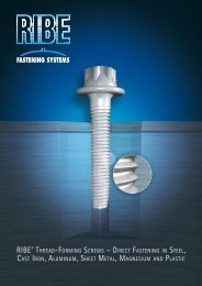
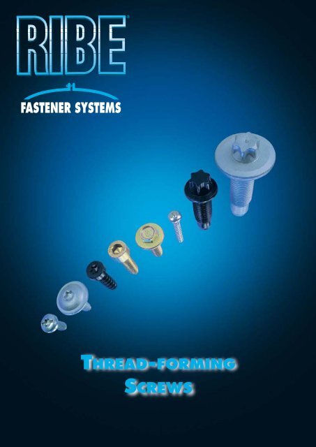
THREAD-FORMING<br />
SCREWS
DIRECT FASTENING<br />
Direct fastening of components without mating <strong>thread</strong>s can<br />
in many cases significantly lower the overall cost of<br />
mechanical fastening. However to achieve these savings,<br />
fasteners with special characteristics are required. <strong>RIBE</strong> ® offers<br />
a broad range of specially designed <strong>screws</strong> in a wide range of<br />
lengths and diameters for all of your fastening needs.<br />
Please note that as direct fastenings require an optimal<br />
interaction between component, fastener and assembly our<br />
technical department is available for your applicationspecific<br />
questions and to help you with your particular<br />
project.<br />
Thread <strong>forming</strong> fasteners create the mating <strong>thread</strong>s themselves.<br />
With <strong>RIBE</strong> ® products this is done by re<strong>forming</strong> the<br />
mating material.<br />
All metals and plastics with sufficient ductility and a<br />
material strength of ca. 650 MPA are appropriate mating<br />
<strong>thread</strong> materials.<br />
<strong>RIBE</strong> ® fasteners are optimized for solid metals (cast iron for<br />
example), for sheet metal, and for plastic components.<br />
There is a fundamental difference between direct screwing<br />
into metal and into plastic. For metals, especially steel, the<br />
screw needs to be extremely hard. This is achieved through<br />
quenching and tempering to high strength, case hardening,<br />
or through inductive hardening. The <strong>thread</strong> profile generally<br />
corresponds to that of metric <strong>thread</strong>. For plastics on the other<br />
hand, slender, tapered flanks with a coarser pitch are more<br />
suitable. Quenched and tempered steel is sufficient for these<br />
<strong>screws</strong>, and additional hardening of the surface or coating is<br />
unnecessary.<br />
<strong>RIBE</strong> ® ’s years of experience have produced both a product<br />
program and corresponding application guidelines that are in<br />
use throughout the world.<br />
When not to use <strong>thread</strong>-<strong>forming</strong> <strong>screws</strong>?<br />
When the difference in material strength between screw<br />
and mating material is negligible.<br />
With materials that are not <strong>thread</strong>able such as brittle<br />
metals, minimum elongation at rupture should be ca. 50%.<br />
With the highest demanded prestressing force.<br />
ADVANTAGES<br />
Direct fastening with <strong>thread</strong> <strong>forming</strong> <strong>screws</strong> offers the<br />
following advantages:<br />
➀ No mating material is removed consequently no chips<br />
are produced during assembly. There is no weakening of<br />
the mating material. This is particularly advantageous when<br />
using thin-walled components.<br />
➁There is no need to cut <strong>thread</strong>s. This means no <strong>thread</strong><br />
cutting processes, no tool costs, and a faster turnaround<br />
time. The result is lower costs.<br />
➂ Faster assembly using stamped, cast or drilled holes<br />
without chip producing prep work.<br />
➃ When screwing takes place the mating <strong>thread</strong> is work-<br />
hardened and self-stressed, so that it is generally capable<br />
of bearing a greater load.<br />
➄ Because of the „insertion torque“ and the perfect fit bet-<br />
ween the external and internal <strong>thread</strong>s, there is far<br />
greater resistance to loosening, so that additional screw<br />
locking devices are usually not necessary.<br />
➅ No stripping of mating <strong>thread</strong>s during assembly.<br />
Summary:<br />
Significant cost- savings and improved assembly procedures<br />
can be achieved with <strong>thread</strong>-<strong>forming</strong> direct fasteners.<br />
For many applications mating <strong>thread</strong>s are not cut; rather they<br />
are formed during component manufacture. However advantages<br />
➁, ➂, ➄ and ➅ still apply in these cases.
DIRECT FASTENING INTO DEEP<br />
MATING-THREADS FOR METALS<br />
Most of these fasteners have a metric <strong>thread</strong> profile insuring<br />
interchangeability with standard metric <strong>screws</strong>. These fasteners<br />
are designed to form a metric mother <strong>thread</strong> so that if<br />
necessary a screw with metric <strong>thread</strong>s can be fitted, (for example<br />
if repair is required and the original screw is not available).<br />
The following <strong>screws</strong> have crests of different specifications<br />
to produce optimal mating-<strong>thread</strong>s. All these <strong>screws</strong> have<br />
sharp, trilobular crests for rapid and tight engagement during<br />
assembly.<br />
Guidelines for the dimensions of drilled, punched, or cast holes<br />
are listed here as well as parameters for installation and tightening<br />
torques (VDI 2230). In particular the torque values<br />
should be considered only as approximate guidelines, due to<br />
the wide range of variables in material performance, surfaces<br />
and lubrications. Especially in the case of critical combinations,<br />
for example shallow holes or low ductility mating material,<br />
we strongly recommend testing to determine the optimal<br />
dimensions.<br />
Component with <strong>thread</strong>-<strong>forming</strong> <strong>screws</strong><br />
METAL FASTENERS<br />
MATERIALS AND DESIGN<br />
<strong>RIBE</strong> ® TRIFORM , <strong>RIBE</strong> ® -TAPTITE II ® and <strong>RIBE</strong> ® -DUO-TAPTITE ® are<br />
available in the following materials:<br />
Case-hardened (DIN EN ISO 7085)<br />
CORFLEX ® N quenched and hardened with controlled<br />
recarborization - property classes 8.8, 10.9 and 12.9<br />
(DIN EN 20898)<br />
CORFLEX ® I with an inductively hardened <strong>thread</strong>-<strong>forming</strong><br />
crest.<br />
If no special demands on the dynamic strength or ductility<br />
of the screw are required, case-hardened quality is sufficient<br />
(DIN 7500). Example: mating <strong>thread</strong>s with strengths of up to<br />
about 650 MPa or hardness of up to about 200 HB.<br />
Quenched and tempered <strong>screws</strong> of property classes 8.8 or 10.9<br />
are particularly suited for <strong>forming</strong> mating <strong>thread</strong>s in light<br />
metals (CORFLEX ® N, mating <strong>thread</strong> strength up to about 400<br />
MPa or hardness 120 HB). Quenched and tempered <strong>screws</strong><br />
with inductively hardened <strong>thread</strong>-<strong>forming</strong> crests are capable<br />
of <strong>forming</strong> mating <strong>thread</strong>s in metals with strengths of up to<br />
650 MPa, at the same time meeting the highest ductility and<br />
stress resistance requirements (CORFLEX ® I, mating <strong>thread</strong><br />
strength up to about 650 MPa or hardness 200 HB).<br />
The CORFLEX ® designs enable <strong>thread</strong>-<strong>forming</strong> <strong>screws</strong> to be<br />
used for fastenings that are subject to high static and<br />
dynamic stresses.<br />
Sample installation curve for <strong>thread</strong>-<strong>forming</strong><br />
screw M8 with crest in blind hole
TRIFORM <br />
The TRIFORM screw has been specially developed by <strong>RIBE</strong> ®<br />
and has proven its qualities over many years. It combines low<br />
installation torque and high proof-load with a reasonable<br />
price. This is achieved through the combination of the easyto-manufacture<br />
TRIFORM <strong>thread</strong>-<strong>forming</strong> crest and the round<br />
shank. It is particularly suitable for use with cost-optimized<br />
parts and mating <strong>thread</strong> materials with low malleability.<br />
TAPTITE II ®<br />
The TAPTITE II ® screw is characterized by a high degree of shank<br />
lobulation (out-of-roundness, the difference between<br />
dimensions C and D). This makes for a very low insertion<br />
torque. The screw „engages“ with only negligible axial contact<br />
force. In spite of this, the <strong>thread</strong>-<strong>forming</strong> crest with 2 to 3<br />
turns exceeds the requirements DIN 7500-1. Lobulation over<br />
the entire length of the shank guarantees consistently low<br />
insertion torque, even with a large <strong>thread</strong> depth.<br />
DUO-TAPTITE ®<br />
The DUO-TAPTITE ® screw has a <strong>thread</strong>-<strong>forming</strong> crest and guide<br />
pin that facilitates correct centering in the pilot hole (good<br />
axial alignment of the screw). The lobulation of the <strong>thread</strong><strong>forming</strong><br />
crest is greater than that of the shank. This produces<br />
a combination of low insertion torque and a high axial proofload<br />
(high stripping torque, high pullout force).
METAL FASTENERS<br />
TRIFORM grinding pattern<br />
TAPTITE II ® grinding pattern<br />
DUO-TAPTITE ® grinding pattern
DESIGN DATA<br />
These tables provide details of <strong>thread</strong> sizes, guidelines for sizing<br />
the pilot hole for drilling, punching or casting, as well as<br />
recommended values for insertion and tightening torque.<br />
The listed values apply equally to TRIFORM , TAPTITE II ® , and<br />
DUO-TAPTITE ® , as these products differ only in areas that are<br />
not relevant for these guidelines.<br />
TAPTITE II<br />
C D<br />
Thread (mm) min. max. min. max.<br />
M 2,0 1,98 2,06 1,90 1,98<br />
M 2,5 2,48 2,57 2,39 2,48<br />
M 3,0 2,98 3,07 2,88 2,97<br />
M 3,5 3,48 3,58 3,36 3,46<br />
M 4,0 3,98 4,08 3,84 3,94<br />
M 5,0 4,98 5,09 4,82 4,93<br />
M 6,0 5,97 6,10 5,77 5,90<br />
M 8,0 7,97 8,13 7,72 7,88<br />
M 10,0 9,97 10,15 9,67 9,85<br />
M 12,0 11,97 12,18 11,62 11,83<br />
® - <strong>thread</strong> dimensions<br />
TRIFORM - <strong>thread</strong> dimensions<br />
Thread (mm) d1 max z1 max<br />
M 2,5 2,60 1,50<br />
M 3,0 3,10 1,60<br />
M 3,5 3,61 2,00<br />
M 4,0 4,12 2,30<br />
M 5,0 5,12 2,60<br />
M 6,0 6,12 3,30<br />
M 8,0 8,16 4,10<br />
M 10,0 10,18 5,00<br />
DUO-TAPTITE ® - <strong>thread</strong> dimensions<br />
Thread C D cp<br />
(mm) min. max. min. max. max.<br />
M 2,0 1,98 2,06 1,94 2,02 1,75<br />
M 2,5 2,48 2,57 2,44 2,52 2,22<br />
M 3,0 2,98 3,07 2,93 3,02 2,69<br />
M 3,5 3,48 3,58 3,42 3,52 3,13<br />
M 4,0 3,98 4,08 3,91 4,01 3,57<br />
M 5,0 4,98 5,09 4,90 5,01 4,51<br />
M 6,0 5,97 6,10 5,87 6,00 5,38<br />
M 8,0 7,97 8,13 7,85 8,00 7,23<br />
M 10,0 9,97 10,15 9,82 10,00 9,07<br />
M 12,0 11,97 12,18 11,80 12,00 10,92<br />
M 14,0 13,97 14,20 13,77 14,00 12,77<br />
M 16,0 15,97 16,20 15,77 16,00 14,77<br />
Guidelines for installation and tightening torque for TRIFORM , TAPTITE II ® and DUO-TAPTITE ®<br />
Torque values given in Nm M 2,0 M 2,5 M 3,0 M 3,5 M 4,0 M 5,0 M 6,0 M 8,0 M 10,0 M 12,0 M 14,0 M 16,0<br />
Insertion torque** 0,1...0,2 0,2...0,4 0,3...0,7 0,5...1,1 0,7...1,6 1,5...3,5 2,5...6,0 7...15 15...30 25...52 35...70 55...115<br />
Transit hole beyond the <strong>thread</strong>-<strong>forming</strong> crest<br />
Tightening torque 8.8* 0,4 0,7 1,3 1,9 2,8 5,5 9,9 23,4 45,9 78,3 130,5 198,0<br />
Tightening torque 10.9 0,5 1,0 1,8 2,7 4,1 8,0 14,0 33,3 67,5 115,2 189,0 288,0<br />
Tightening torque 12.9 0,7 1,2<br />
Blind hole<br />
2,1 3,2 4,7 9,4 16,2 38,7 78,3 135,0 216,0 342,0<br />
Tightening torque 8.8* 0,4 0,8 1,5 2,2 3,3 6,4 11,6 27,3 53,6 91,4 152,3 231,0<br />
Tightening torque 10.9 0,6 1,2 2,1 3,2 4,7 9,3 16,3 38,9 78,8 134,4 220,5 336,0<br />
Tightening torque 12.9 0,8 1,4 2,4 3,7 5,5 10,9 18,9 45,2 91,4 157,5 252,0 399,0<br />
Due to the wide range of variable factors in material performance, surfaces and lubrications, these torque values should be considered as approximate guidelines only. We recommend some testing to<br />
determine the optimal dimensions, particularly in the case of critical component combinations, for example shallow holes in a low ductility mating material. Torque prerequisites are appropriate hole<br />
dimensions and adequate <strong>thread</strong> depth. Optimal assembly recommendations must be determined experimentally.<br />
* The values given for 8.8 <strong>screws</strong> apply to DIN 7500 <strong>screws</strong> as well.<br />
** Even the highest installation torque values are within the DIN 7500 specification.
Guidelines for the diameter of cylindrical bore-holes for TRIFORM , TAPTITE II ® and DUO-TAPTITE ® in mm<br />
Thread depth /<br />
Material thickness<br />
M 2,0 M 2,5 M 3,0 M 3,5 M 4,0 M 5,0 M 6,0 M 8,0 M 10,0 M 12,0 M 14,0 M 16,0<br />
s (mm) Allowance over nominal size for the bore-hole (mm)<br />
s up to 0,050 +0,050 +0,075 +0,075 +0,075 +0,075 +0,090 +0,090 +0,110 +0,110 +0,110 +0,110<br />
s 0,05 to 1,0 1,80 2,25 2,70<br />
s 1,0 to 1,6 1,80 2,25 2,70 3,20<br />
s 1,6 to 2,5 1,85 2,25 2,75 3,20 3,65 4,50 5,40<br />
s 2,5 to 4,0 1,85 2,30 2,75 3,20 3,65 4,55 5,50 7,30 9,30<br />
s 4,0 to 6,3 2,30 2,75 3,25 3,70 4,65 5,50 7,40 9,30 11,10<br />
s 6,3 to 10,0 3,70 4,65 5,55 7,50 9,40 11,10<br />
s 10,0 to 16,0 7,50 9,40 11,20 13,20 15,20<br />
s 16,0 to 25,0 7,60 9,50 11,30 13,20 15,20<br />
Larger bore diameters reduce the installation torque; smaller ones increase the durability of the mating <strong>thread</strong> and resistance to loosening. For malleable materials with low strength, e.g.<br />
aluminium alloys, the diameter of the hole can be reduced by about 0.05 mm. Bore-hole tolerances: H11 in accordance with DIN ISO 286.<br />
Guidelines for bore diameter d B for rim holes in sheet metal for TRIFORM , TAPTITE II ® and DUO-TAPTITE ® in mm<br />
Sheet thickness s (mm) M 2,5 M 3,0 M 3,5 M 4,0 M 5,0 M 6,0 M 8,0 M 10,0 M 12,0<br />
0,5 2,21...2,24 2,68...2,71<br />
0,8 2,23...2,26 2,71...2,74 3,15...3,18<br />
1,0 2,25...2,28 2,74...2,77 3,16...3,21 3,57...3,62 4,48...4,54<br />
METAL FASTENERS<br />
1,5 2,27...2,30 2,77...2,80 3,19...3,24 3,60...3,65 4,51...4,57 5,38...5,45 7,19...7,27<br />
2,0 3,64...3,69 4,54...4,60 5,41...5,48 7,22...7,30 9,08...9,17<br />
3,0 4,57...4,63 5,44...5,51 7,25...7,33 9,13...9,22 10,90...11,00<br />
4,0 7,30...7,38 9,18...9,27 10,95...11,05<br />
5,0 9,26...9,35 11,00...11,10<br />
Sizing of the rim-holes as in the diagram; cf. also DIN 7952. The production of crack-free rim holes requires a material with a high elongation at rupture. Recommended size of pilot hole in sheet metal:<br />
0.5 x nominal screw diameter.<br />
Sizing guidelines for cast bore-holes for TRIFORM , TAPTITE II ® and DUO-TAPTITE ® in mm<br />
Values in mm M 4 M 5 M 6 M 8 M 10 M 12 M 14 M 16<br />
do 3,73 4,72 5,66 7,60 9,55 11,50 13,45 15,45<br />
du 3,55 4,50 5,40 7,26 9,13 11,00 12,80 14,80<br />
Upper gap for do and du* +0,030 +0,030 +0,036 +0,036 +0,043 +0,043 +0,043 +0,043<br />
da* 6,50 8,50 10,00 13,00 17,00 20,00 24,00 27,00<br />
ts 0,70 0,80 1,00 1,30 1,50 1,80 2,00 2,00<br />
ds 4,20 5,20 6,30 8,30 10,40 12,40 14,50 16,50<br />
Upper gap for da, ts and ds* +0,075 +0,075 +0,090 +0,09 +0,110 +0,110 +0,110 +0,110<br />
I for high-strength materials, e.g. cast steel α ca. 1,5° 6,70 8,30 9,80 12,80 16,40 19,50 21,70 25,00<br />
I for medium-strength materials, e.g. gray cast iron, aluminium, and zinc; α ca. 1,1° 8,20 10,30 12,40 16,40 20,50 24,50 28,70 33,00<br />
I for low-strength materials, e.g. magnesium, aluminium, α ca. 0,8°* 12,40 15,40 18,50 24,50 30,70 36,80 43,00 49,00<br />
* Where lesser load capacity is required, larger tolerances, diferent external diameters of the casting dome, or different tapers may be used.
TRIFORM <br />
DB<br />
AND EXTRUDE-TITE ®<br />
The products TRIFORM DB and EXTRUDE-TITE ® described<br />
below are <strong>thread</strong>-<strong>forming</strong> <strong>screws</strong> with a particularly long<br />
<strong>thread</strong>-<strong>forming</strong> crest, which produces a definite axial alignment<br />
of the screw during assembly. This fastener design also<br />
produces a small diameter rim-hole in sheet metals.<br />
In contrast to conventional sheet metal <strong>screws</strong>, the large web<br />
section facilitates substantial re<strong>forming</strong> of the mating <strong>thread</strong><br />
material and provides a high stripping torque. Due to the<br />
plastic re<strong>forming</strong> of the mating material it is possible to<br />
create a fastening with a high proof-load, even in thinwalled<br />
materials like sheet metals.<br />
ADVANTAGES<br />
Reduced costs because of easier assembly:<br />
No mating <strong>thread</strong>s are necessary<br />
Fewer operations on the component, e.g. no rim hole in<br />
sheet metal is necessary<br />
No additional tools or parts needed (e.g. weld nuts or sheet<br />
metal nuts)<br />
Thinner component walls can be implemented<br />
These fasteners offer:<br />
Easy and safe assembly<br />
No vibration induced loosening due to perfectly mated<br />
<strong>thread</strong>s<br />
Relatively high locking force<br />
No need to clean the mating <strong>thread</strong> (e.g. after painting)<br />
Sample installation curve for thin sheet metal screw M5
SCREWS FOR SHEET METALS<br />
TRIFORM <br />
DB<br />
This screw is based on the tried and tested TRIFORM formu-<br />
la: a high performance fastener at a good price. The performance<br />
is achieved by the <strong>forming</strong> surfaces on the <strong>thread</strong><strong>forming</strong><br />
crest and the cylindrical shank.<br />
The flanks of the <strong>thread</strong> are fully formed to the crest.<br />
The TRIFORM DB screw can be used wherever the highest<br />
operational efficiency is called for with sheet metal components.<br />
TRIFORM DB grinding pattern
EXTRUDE-TITE ®<br />
The EXTRUDE-TITE ® screw is slightly out-of-round along the<br />
whole length of the shank, resulting in a very low installation<br />
torque in sheet metals. It thus provides a high level of<br />
assembly security, even under difficult circumstances.<br />
With this model as well, the flanks of the <strong>thread</strong> are fully<br />
formed to the crest.<br />
EXTRUDE-TITE ® grinding pattern
FASTENERS FOR SHEET METALS<br />
DESIGN DATA<br />
The following three factors are significant for the selection<br />
of <strong>screws</strong> for direct fastening into sheet metal:<br />
The bore diameter of the pilot hole in the component<br />
The installation torque required during assembly<br />
The tightening torque that can safely be applied.<br />
These three values are specified in the tables.<br />
For direct fastening into sheet metals, the component is<br />
usually the weak point when the fastening is overstressed. It<br />
is therefore essential to carefully plan the assembly<br />
procedure. Because of the variety of factors that can influence<br />
the process, the values given in the tables are only<br />
approximate guidelines and should be checked in each<br />
individual case.<br />
With direct fastenings in sheet metals, modern assembly<br />
methods in conjunction with several screw levels help<br />
ensure security of installation. This means that <strong>screws</strong> with<br />
an insertion torque exceeding the tightening torque can be<br />
securely installed. In many cases the right screw combined<br />
with the correct assembly procedure can open up additional<br />
application opportunities. We would be pleased provide<br />
further information in this regard.<br />
Hole diameters and torques for TRIFORM DB and EXTRUDE-TITE ®<br />
TRIFORM DB - <strong>thread</strong> dimensions<br />
Thread d 2 z d 1<br />
(mm) max. max. max.<br />
M 3 1,50 3,50 3,10<br />
M 4 2,00 4,90 4,12<br />
M 5 2,50 5,60 5,12<br />
M 6 3,00 7,00 6,12<br />
M 8 4,40 8,80 8,16<br />
EXTRUDE-TITE ® - <strong>thread</strong> dimensions<br />
Thread C D Cp LP<br />
(mm) max. min. max. min. max. max.<br />
M 3 3,07 2,98 3,02 2,93 1,26 2,75<br />
M 4 4,08 3,98 4,01 3,91 1,56 3,85<br />
M 5 5,09 4,98 5,01 4,90 2,21 4,40<br />
M 6 6,10 5,97 6,00 5,87 2,51 5,50<br />
M 8 8,13 7,97 8,01 7,85 3,64 6,88<br />
Sheet thickness Bore hole diameter (mm) Insertion torque guideline (Nm) Tightening torque guideline (Nm)<br />
(mm) M 3 M 4 M 5 M 6 M 3 M 4 M 5 M 6 M 3 M 4 M 5 M 6<br />
0,75 1,8 2,4 3,5 0,5 1,3 2,0 0,8 2,5 4,0<br />
0,80 1,8 2,4 3,6 4,6 0,5 1,4 2,0 2,3 0,9 2,5 4,5 5,0<br />
0,90 1,8 2,4 3,8 4,7 0,6 1,4 2,1 2,5 1,0 2,5 5,0 6,0<br />
1,00 2,0 2,5 3,9 4,8 0,6 1,6 2,2 2,7 1,1 3,0 5,0 6,0<br />
1,25 2,2 2,7 4,1 4,9 0,7 1,6 2,3 3,0 1,2 3,0 5,0 7,0<br />
1,50 2,9 4,2 5,0 1,7 2,5 3,2 3,0 5,0 8,0<br />
2,00 3,1 4,3 5,1 1,8 2,7 3,6 3,5 6,0 10,0<br />
2,50 4,5 5,2 2,9 3,9 6,0 10,0<br />
The values listed apply to cylindrical boreholes without rim holes. Because of the range of factors that may influence the fastening, such as materials, surfaces, and lubrication, the approximate values<br />
given here may vary in individual cases.
Plastic components are lightweight and inexpensive. The most<br />
suitable fasteners for plastics are <strong>screws</strong> that can be screwed<br />
directly into the material without any mating <strong>thread</strong>.<br />
Because of the great flexibility offered by plastics, an out-ofround<br />
screw is not necessary. In order to achieve a high proof<br />
load, these <strong>screws</strong> have a relatively coarse pitch and a small<br />
body diameter.<br />
<strong>RIBE</strong> ® ’s PLASTOFORM and PR <strong>screws</strong> ensure a high level of<br />
reliability, which can be further increased by optimized design<br />
and assembly of the component.<br />
ADVANTAGES<br />
Cost-effective fastening<br />
With the correct dimensioning and the right choice of<br />
screw, a reliable and durable fastening is achieved<br />
Quick assembly<br />
Reduced component tooling<br />
(no machining, no inserts)<br />
Reusability<br />
Sample insertion curve for Plastoform P5
PLASTOFORM<br />
The PLASTOFORM <strong>thread</strong> profile has been constantly refined<br />
through computer modeling as well as practical research, with<br />
the result that the same screw can be used for fastening both<br />
ductile and brittle plastics. The screw is designed to produce<br />
a low insertion torque. The component material is compressed<br />
through the curves to produce a high proof load. In<br />
addition, the PLASTOFORM design reduces the radial stress in<br />
the plastic, thus reducing the risk of splitting in the screw<br />
dome. In addition the low-notch shaping makes the screw<br />
highly resistant to dynamic stress.<br />
PLASTOFORM <strong>screws</strong> are used wherever the highest fastening<br />
requirements must be fulfilled.<br />
PLASTOFORM - <strong>thread</strong> dimensions (mm)<br />
SCREWS FOR PLASTICS<br />
<strong>RIBE</strong> ® -PLASTOFORM grinding pattern<br />
Threads P 3,0 P 3,5 P 4,0 P 4,5 P 5,0 P 5,5 P 6,0 P 6,5<br />
a 1,30 +0,50 1,50 +0,50 1,80 +0,60 1,80 +0,70 2,20 +0,80 2,40 +0,80 2,50 +0,90 2,90 +1,00<br />
b 12,00 +1,90 14,00 +2,30 16,00 +2,70 18,00 +2,60 20,00 +3,20 22,00 +3,50 24,00 +3,80 26,00 +4,30<br />
d1 3,00-0,20 3,50-0,20 4,00-0,25 4,50-0,25 5,00-0,25 5,50-0,25 6,00-0,25 6,50-0,25 d2 1,87-0,20 2,03-0,20 2,50-0,20 2,70-0,25 2,96-0,25 3,35-0,25 3,64-0,25 3,83-0,25 P 1,27 1,53 1,78 1,84 2,15 2,35 2,54 2,87<br />
x max. 1,30 1,60 1,80 1,90 2,20 2,40 2,60 2,90<br />
y max. 1,30 1,60 1,80 1,90 2,20 2,40 2,60 2,90
<strong>RIBE</strong> ®<br />
PR<br />
The <strong>RIBE</strong> ® PR <strong>thread</strong> profile has been developed for applicati-<br />
ons requiring mid level fastening demands at a low price. The<br />
screw has narrow 30º flanks, providing excellent engagement<br />
between the screw <strong>thread</strong> and the plastic mating material. The<br />
body diameter is designed so that the plastic generally is not<br />
compressed right to the root of the <strong>thread</strong>.<br />
<strong>RIBE</strong> ® PR - <strong>thread</strong> dimensions<br />
<strong>RIBE</strong> ® PR grinding pattern<br />
Threads PR 1,8 PR 2,0 PR 2,2 PR 2,5 PR 3,0 PR 3,5 PR 4,0 PR 5,0 PR 6,0 PR 7,0<br />
a min 1,30 1,40 1,50 1,70 1,90 2,10 2,40 3,00 3,60 4,20<br />
b 7,00 +1,1 8,00 +1,3 9,00 +1,4 10,00 +1,6 12,00 +1,9 14,00 +2,3 16,00 +2,7 20,00 +3,2 24,00 +3,8 28,00 +4,5<br />
d 1 (h13) 1,95 2,15 2,35 2,65 3,15 3,65 4,15 5,15 6,15 7,20<br />
d 2 (h12) 1,20 1,32 1,43 1,60 1,90 2,18 2,48 3,04 3,63 4,20<br />
d 3 1,50 1,60 1,70 1,90 2,30 2,60 3,00 3,60 4,25 4,90<br />
P 0,80 0,91 0,98 1,12 1,34 1,57 1,79 2,24 2,69 3,14<br />
x max 0,80 0,90 1,00 1,20 1,40 1,60 1,80 2,20 2,70 3,20<br />
y max 0,80 0,90 1,00 1,20 1,40 1,60 1,80 2,20 2,70 3,20
DESIGN DATA<br />
For plastics the starting point for the correct sizing of directly<br />
screwed fastenings is the required locking force, which is<br />
limited by the maximum fracture force for the screw. The table<br />
below gives standard values for the required bore-hole<br />
diameter as well as the anticipated insertion and tightening<br />
torques for each screw size.<br />
The tensile strength of the plastic determines the screw<br />
insertion depth.<br />
In the adjacent table the most frequently used plastics are<br />
listed. Using the tensile strength values the corresponding<br />
insertion depth and the corresponding nominal diameter of<br />
the screw dome can be identified. This information along with<br />
suggestions for a screw enclosure allows a rapid determination<br />
of both screw dimensions and the component fastening<br />
area. Please note that for special fastening requirements these<br />
guidelines should be checked and revised through experiment<br />
if necessary.<br />
SCREWS FOR PLASTICS<br />
Guidelines for the sizing of direct fasteners in plastic<br />
Guidelines for tensile strength in plastic<br />
Plastic σ (MPa)<br />
ABS 50<br />
Epoxy resin 65...110<br />
Polyamide PA6 dry ... air humidity 3% H 2 O 85...30<br />
Polyamide PA6 GF 30 dry ... air humidity 3% H 2 O 170...100<br />
Polyamide PA6 GF 50 dry ... air humidity 3% H 2 O 190...120<br />
Polyamide PA66 dry ... air humidity 2,5% H 2 O 85...60<br />
PC 60<br />
PC GF 30 80<br />
Polyethylene 30<br />
Polymethylene oxide 65<br />
Polypropylene 30<br />
Polyurethane 50<br />
Hard PVC 65<br />
SAN 70<br />
Unsaturated polyester 75<br />
The tensile strength σ is based on the yield stress, 1% extension stress, or the fracture<br />
strength, depending on the characteristics of the type of plastic involved. The values given<br />
are guidelines for arriving at a quick estimate. For fastenings with little relaxation, the tensile<br />
strength should be reduced by a factor of 0,5 to 0,8.<br />
Characteristic values for PLASTOFORM and PR <strong>screws</strong><br />
Type<br />
PR 2,00<br />
P 3,00<br />
PR 2,50<br />
P 3,50<br />
PR 3,00<br />
P 4,00<br />
PR 3,50<br />
P 4,50<br />
PR 4,00<br />
P 5,00 P 5,50<br />
PR 5,00<br />
P 6,00 P 6,50<br />
PR 6,00 PR 7,00<br />
Nominal diameter d1 (mm) 2,00 2,50 3,00 3,50 4,00 4,50 5,00 5,50 6,00 6,50 7,00<br />
Screw fracture force (N) 950,00 1400,00 1750,00 2100,00 3300,00 3800,00 4600,00 6000,00 7200,00 8100,00 9500,00<br />
dB<br />
ductile plastic (mm)* 1,60 2,00 2,40 2,80 3,40 3,80 4,20 4,60 5,10 5,50 5,50<br />
dB<br />
brittle plastic (mm)* 1,80 2,10 2,60 3,00 3,60 4,00 4,50 5,00 5,40 5,90 5,90<br />
Approx. insertion torque (Nm) 0,10 0,20 0,50 0,70 0,80 1,20 1,50 2,00 3,00 4,00 5,00<br />
Approx. tightening torque (Nm) 0,25 0,50 1,00 1,40 1,60 2,40 3,00 4,50 6,00 8,00 10,00<br />
These values are for approximate guidance only, as they can be influenced by a number of parameters (e.g. materials, surfaces, geometry, assembly conditions). Optimized fastenings generally require<br />
adjustments to d B , l E , d a . * Bore-hole tolerance +0.05 mm.
Richard Bergner Verbindungstechnik GmbH & Co. KG<br />
Bahnhofstr. 8-16 · D-91126 Schwabach · Germany · Telefon +49 (0) 91 22 / 87-0 · Telefax +49 (0) 91 22 / 87-1507<br />
E-mail Verbindungstechnik@ribe.de · Internet www.ribe.de<br />
CMB Communications<br />
VT/106/2/0103/2.0