RF Signal Generator - Prager Elektronik
RF Signal Generator - Prager Elektronik
RF Signal Generator - Prager Elektronik

You also want an ePaper? Increase the reach of your titles
YUMPU automatically turns print PDFs into web optimized ePapers that Google loves.
· DC to 4.05 GHz<br />
· 1 µHz resolution<br />
· AM, FM, ΦM, PM and sweeps<br />
· OCXO timebase (std.)<br />
· −116dBc/Hz SSB phase noise<br />
(20 kHz offset, f = 1 GHz)<br />
· Rubidium timebase (opt.)<br />
· Square wave clock outputs (opt.)<br />
· Analog I/Q inputs (opt.)<br />
· Ethernet, GPIB, and RS-232<br />
· SG384 ... $4,600 (U.S. list)<br />
www.thinkSRS.com<br />
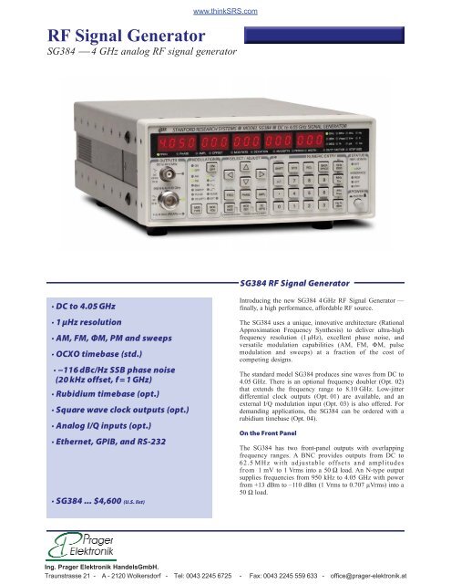
<strong>RF</strong> <strong>Signal</strong> <strong>Generator</strong><br />
SG384 ⎯ 4 GHz analog <strong>RF</strong> signal generator<br />
SG384 <strong>RF</strong> <strong>Signal</strong> <strong>Generator</strong><br />
Introducing the new SG384 4 GHz <strong>RF</strong> <strong>Signal</strong> <strong>Generator</strong> —<br />
finally, a high performance, affordable <strong>RF</strong> source.<br />
The SG384 uses a unique, innovative architecture (Rational<br />
Approximation Frequency Synthesis) to deliver ultra-high<br />
frequency resolution (1 µHz), excellent phase noise, and<br />
versatile modulation capabilities (AM, FM, ΦM, pulse<br />
modulation and sweeps) at a fraction of the cost of<br />
competing designs.<br />
The standard model SG384 produces sine waves from DC to<br />
4.05 GHz. There is an optional frequency doubler (Opt. 02)<br />
that extends the frequency range to 8.10 GHz. Low-jitter<br />
differential clock outputs (Opt. 01) are available, and an<br />
external I/Q modulation input (Opt. 03) is also offered. For<br />
demanding applications, the SG384 can be ordered with a<br />
rubidium timebase (Opt. 04).<br />
On the Front Panel<br />
The SG384 has two front-panel outputs with overlapping<br />
frequency ranges. A BNC provides outputs from DC to<br />
62.5 MHz with adjustable offsets and amplitudes<br />
from 1 mV to 1 Vrms into a 50 Ω load. An N-type output<br />
supplies frequencies from 950 kHz to 4.05 GHz with power<br />
from +13 dBm to –110 dBm (1 Vrms to 0.707 µVrms) into a<br />
50 Ω load.<br />
Ing. <strong>Prager</strong> <strong>Elektronik</strong> HandelsGmbH.<br />
Traunstrasse 21 - A - 2120 Wolkersdorf - Tel: 0043 2245 6725 - Fax: 0043 2245 559 633 - office@prager-elektronik.at
Modulation<br />
The SG384 offers a wide variety of modulation capabilities.<br />
Modes include amplitude modulation (AM), frequency<br />
modulation (FM), phase modulation (ΦM), and pulse<br />
modulation. There is an internal modulation source as well as<br />
an external modulation input. The internal modulation source<br />
produces sine, ramp, saw, square, and noise waveforms.<br />
An external modulation signal may be applied to the rearpanel<br />
modulation input. The internal modulation generator is<br />
available on the rear-panel modulation output.<br />
Unlike traditional analog signal generators, the SG384 can<br />
sweep continuously from DC to 62.5 MHz. And for<br />
frequencies above 62.5 MHz, each sweep range covers more<br />
than an octave.<br />
OCXO or Rubidium Timebase<br />
The SG384 comes with a oven-controlled crystal oscillator<br />
(OCXO) timebase. The timebase uses a third-overtone stresscompensated<br />
10 MHz resonator in a thermostatically controlled<br />
oven. The timebase provides very low phase noise and very<br />
low aging. An optional rubidium oscillator (Opt. 04) may be<br />
ordered to substantially reduce frequency aging and improve<br />
temperature stability.<br />
The internal 10 MHz timebase (either the standard OCXO or<br />
the optional rubidium reference) is available on a rear-panel<br />
output. An external 10 MHz timebase reference may be<br />
supplied to the rear-panel timebase input.<br />
Square Wave Clock Outputs<br />
Optional differential clock outputs (Opt. 01) are available on<br />
the rear panel which make the SG384 a precision clock<br />
Differential Clock Outputs<br />
Option 01 provides differential clock outputs at rates<br />
from DC to 4.05 GHz with 1 µHz resolution. The<br />
clocks have transition times of about 35 ps. Both the<br />
offset and amplitude of the clock outputs can be<br />
adjusted for compliance with standard logic levels.<br />
Shown here at 2 ns/division; 100 MHz front panel sine<br />
wave output (top trace) and differential clock outputs<br />
(bottom traces). The displayed transition times are<br />
limited by the 1.5 GHz bandwidth of the oscilloscope.<br />
Phase Noise (dBc/Hz)<br />
SG384 <strong>RF</strong> <strong>Signal</strong> <strong>Generator</strong><br />
SG384 Phase Noise vs. Offset Frequency<br />
-40<br />
-50<br />
-60<br />
-70<br />
-80<br />
-90<br />
-100<br />
-110<br />
-120<br />
-130<br />
-140<br />
10 MHz<br />
100 MHz<br />
1 GHz<br />
-150<br />
10 100 1,000 10,000 100,000 1,000,000 10,000,000<br />
Frequency Offset (Hz)<br />
The SG384 always synthesizes a frequency in the top<br />
octave (2 GHz to 4 GHz) and digitally divides to<br />
generate outputs at lower frequencies. Doing so creates<br />
phase noise characteristics which scale with output<br />
frequency by 6 dB/octave or 20 dB/decade.<br />
The low phase noise at small offsets (for example,<br />
–80 dBc/Hz at 10 Hz offset from 1 GHz) is attributable<br />
to the low phase noise OCXO timebase reference<br />
oscillator. An important figure of merit for<br />
communications applications is the phase noise at<br />
20 kHz offset, which is about –116 dBc/Hz at 1 GHz.<br />
Amplitude Modulation (100 %)<br />
The frequency range of the SG384 extends from DC to<br />
4 GHz. All of the analog modulation modes also<br />
extend to DC allowing the SG384 to perform<br />
function generator tasks. Shown here is a 20 kHz carrier<br />
being amplitude modulated by a 1 kHz sine.<br />
Top trace: Modulation output<br />
Bottom trace: Front-panel BNC output<br />
Ing. <strong>Prager</strong> <strong>Elektronik</strong> HandelsGmbH.<br />
Traunstrasse 21 - A - 2120 Wolkersdorf - Tel: 0043 2245 6725 - Fax: 0043 2245 559 633 - office@prager-elektronik.at<br />
4 GHz
generator in addition to a signal generator. Transition times are<br />
typically 35ps, and both the offset and amplitudes of the clock<br />
outputs can be adjusted for compliance with PECL, ECL,<br />
RSECL, LVDS, CML, and NIM levels.<br />
I/Q Inputs<br />
Optional I/Q inputs (Opt. 03) allow I & Q baseband signals to<br />
modulate carriers from 400 MHz to 4.05 GHz. This option also<br />
allows the I/Q modulator to be driven by an internal noise<br />
generator with adjustable bandwidth. Rear-panel outputs allow<br />
the noise source to be viewed or used for other purposes.<br />
I/Q Modulation of 1 GHz Carrier by Internal Noise<br />
<strong>Generator</strong><br />
Option 03 allows I/Q modulation of carriers from<br />
400 MHz to 4.05 GHz. Two signal sources may be used<br />
for I/Q modulation: external I & Q inputs or an internal<br />
noise generator. The external I & Q BNC inputs are<br />
on the rear panel. The internal noise generator has<br />
adjustable noise bandwidth. Shown here is a 1 GHz<br />
carrier being modulated by the internal noise generator<br />
with 1 kHz noise bandwidth.<br />
Output Frequency Doubler<br />
The SG384 can be ordered with a frequency doubler (Opt. 02)<br />
that generates signals from 4.05 GHz to 8.10 GHz. The<br />
amplitude of the rear-panel <strong>RF</strong> output can be adjusted from<br />
–15 dBm to +7 dBm. This option also comes with a bias<br />
source output which can be set with 5 mV resolution over<br />
±10 VDC.<br />
Easy Communication<br />
Remote operation of the SG384 is supported with GPIB,<br />
RS-232 and Ethernet interfaces. All instrument functions<br />
can be controlled and read over any of the interfaces. Up<br />
to nine instrument configurations can be saved in nonvolatile<br />
memory.<br />
SG384 <strong>RF</strong> <strong>Signal</strong> <strong>Generator</strong><br />
Polar Plot of 1.000001 GHz Referenced<br />
to 1 GHz with 100 % AM at 5 kHz<br />
The polar plot shows the trajectory of a signal in the<br />
I/Q plane. An unmodulated carrier at the analyzer’s<br />
reference frequency (1 GHz in this case) appears as a<br />
single dot in the I/Q plane. When the carrier frequency<br />
is offset, the single dot moves in a circle about the<br />
center of the I/Q plane. The pattern shown occurs<br />
when the carrier amplitude is modulated with<br />
100 % depth at a rate of five times the carrier offset<br />
frequency (creating five lobes). The symmetry of<br />
the lobes indicates that there is no residual phase<br />
distortion (AM to ΦM conversion) in the amplitude<br />
modulator. The narrow line of the trajectory is<br />
indicative of low phase and amplitude noise.<br />
Spectrum of Frequency Modulated 50 MHz Carrier<br />
Outputs below 62.5 MHz are generated by directdigital<br />
synthesis with a sample frequency of 1 GHz. In<br />
this example, a 50 MHz carrier is frequency modulated<br />
at a rate of 10 kHz and a deviation of 24.0477 kHz,<br />
for a modulation index β = 2.40477. The carrier<br />
amplitude is proportional to the Bessel function J 0 (β),<br />
which has its first zero at 2.40477.<br />
Ing. <strong>Prager</strong> <strong>Elektronik</strong> HandelsGmbH.<br />
Traunstrasse 21 - A - 2120 Wolkersdorf - Tel: 0043 2245 6725 - Fax: 0043 2245 559 633 - office@prager-elektronik.at
A New Frequency Synthesis Technique<br />
The SG384 is based on a new frequency synthesis technique<br />
called Rational Approximation Frequency Synthesis (RAFS).<br />
RAFS uses small integer divisors in a conventional phaselocked<br />
loop (PLL) to synthesize a frequency that would be<br />
close to the desired frequency (typically within ±100 ppm)<br />
using the nominal PLL reference frequency. The PLL<br />
reference frequency, which is sourced by a voltage controlled<br />
crystal oscillator that is phase locked to a dithered direct<br />
digital synthesizer, is adjusted so that the PLL generates the<br />
exact frequency. Doing so provides a high phase comparison<br />
frequency (typically 25 MHz) yielding low phase noise while<br />
moving the PLL reference spurs far from the carrier where<br />
they can be easily removed. The end result is an agile <strong>RF</strong><br />
source with low phase noise, essentially infinite frequency<br />
resolution, without the spurs of fractional-N synthesis or the<br />
cost of a YIG oscillator.<br />
Unmodulated Spectrum of a 1 GHz Output<br />
The SG384 output exibits low phase noise and low<br />
spurious content. In this direct measurement taken<br />
with 100 Hz RBW, the noise floor of the spectrum<br />
analyzer dominates over most of the 200 kHz span.<br />
SG384 front panel<br />
SG384 <strong>RF</strong> <strong>Signal</strong> <strong>Generator</strong><br />
FSK in the Time Domain<br />
Frequency shift keying (FSK) can be used to transmit<br />
data. In this example, the internal modulator is set<br />
to FM between 1 MHz and 3 MHz with a 100 kHz<br />
square wave.<br />
Top trace: Rear-panel modulation output<br />
Middle trace: Front-panel BNC output<br />
Bottom trace: Front-panel N-type output<br />
Ordering Information<br />
SG384 <strong>RF</strong> <strong>Signal</strong> <strong>Generator</strong> $4,600<br />
Option 01 Rear-panel clock outputs (SMA) $750<br />
Option 02 8 GHz doubler & DC bias $750<br />
Option 03 External I/Q modulation $750<br />
Option 04 Rubidium timebase $1500<br />
RM2U-S Single rack mount kit $100<br />
RM2U-D Dual rack mount kit $100<br />
SG384 rear panel<br />
Ing. <strong>Prager</strong> <strong>Elektronik</strong> HandelsGmbH.<br />
Traunstrasse 21 - A - 2120 Wolkersdorf - Tel: 0043 2245 6725 - Fax: 0043 2245 559 633 - office@prager-elektronik.at
Frequency Setting<br />
Frequency ranges DC to 62.5 MHz (BNC output)<br />
950 kHz to 4.05 GHz (N-type output)<br />
4.05 GHz to 8.1 GHz (opt. 02)<br />
Frequency resolution 1 µHz at any frequency<br />
Switching speed
Amplitude Modulation<br />
Range 0 to 100 % (decreases above +7 dBm)<br />
Resolution 0.1 %<br />
Modulation source Internal or external<br />
Modulation distortion<br />
BNC output