CBC34523 EnerChip™ RTC - PRWeb
CBC34523 EnerChip™ RTC - PRWeb
CBC34523 EnerChip™ RTC - PRWeb
- TAGS
- prweb
- ww1.prweb.com

You also want an ePaper? Increase the reach of your titles
YUMPU automatically turns print PDFs into web optimized ePapers that Google loves.
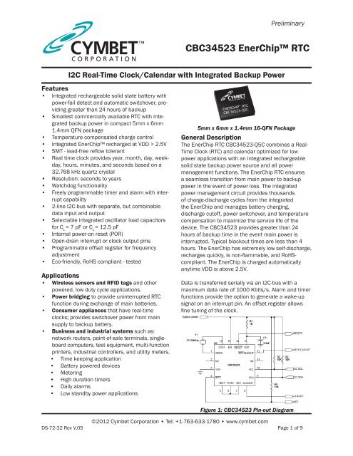
<strong>CBC34523</strong> EnerChip <strong>RTC</strong><br />
I2C Real-Time Clock/Calendar with Integrated Backup Power<br />
Features<br />
• Integrated rechargeable solid state battery with<br />
power-fail detect and automatic switchover, providing<br />
greater than 24 hours of backup<br />
• Smallest commercially available <strong>RTC</strong> with integrated<br />
backup power in compact 5mm x 6mm<br />
1.4mm QFN package<br />
• Temperature compensated charge control<br />
• Integrated EnerChip recharged at VDD > 2.5V<br />
• SMT - lead-free reflow tolerant<br />
• Real time clock provides year, month, day, weekday,<br />
hours, minutes, and seconds based on a<br />
32.768 kHz quartz crystal<br />
• Resolution: seconds to years<br />
• Watchdog functionality<br />
• Freely programmable timer and alarm with interrupt<br />
capability<br />
• 2-line I2C-bus with separate, but combinable<br />
data input and output<br />
• Selectable integrated oscillator load capacitors<br />
for C L = 7 pF or C L = 12.5 pF<br />
• Internal power-on reset (POR)<br />
• Open-drain interrupt or clock output pins<br />
• Programmable offset register for frequency<br />
adjustment<br />
• Eco-friendly, RoHS compliant - tested<br />
Applications<br />
• Wireless sensors and RFID tags and other<br />
powered, low duty cycle applications.<br />
• Power bridging to provide uninterrupted <strong>RTC</strong><br />
function during exchange of main batteries.<br />
• Consumer appliances that have real-time<br />
clocks; provides switchover power from main<br />
supply to backup battery.<br />
• Business and industrial systems such as:<br />
network routers, point-of-sale terminals, singleboard<br />
computers, test equipment, multi-function<br />
printers, industrial controllers, and utility meters.<br />
• Time keeping application<br />
• Battery powered devices<br />
• Metering<br />
• High duration timers<br />
• Daily alarms<br />
• Low standby power applications<br />
Preliminary<br />
5mm x 6mm x 1.4mm 16-QFN Package<br />
General Description<br />
The EnerChip <strong>RTC</strong> <strong>CBC34523</strong>-Q5C combines a Real-<br />
Time Clock (<strong>RTC</strong>) and calendar optimized for low<br />
power applications with an integrated rechargeable<br />
solid state backup power source and all power<br />
management functions. The EnerChip <strong>RTC</strong> ensures<br />
a seamless transition from main power to backup<br />
power in the event of power loss. The integrated<br />
power management circuit provides thousands<br />
of charge-discharge cycles from the integrated<br />
the EnerChip and manages battery charging,<br />
discharge cutoff, power switchover, and temperature<br />
compensation to maximize the service life of the<br />
device. The <strong>CBC34523</strong> provides greater than 24<br />
hours of backup time in the event main power is<br />
interrupted. Typical blackout times are less than 4<br />
hours. The EnerChip has extremely low self-discharge,<br />
recharges quickly, is non-flammable, and RoHScompliant.<br />
The EnerChip is charged automatically<br />
anytime VDD is above 2.5V.<br />
Data is transferred serially via an I2C-bus with a<br />
maximum data rate of 1000 Kbits/s. Alarm and timer<br />
functions provide the option to generate a wake-up<br />
signal on an interrupt pin. An offset register allows<br />
fine tuning of the clock.<br />
Figure 1: <strong>CBC34523</strong> Pin-out Diagram<br />
©2012 Cymbet Corporation • Tel: +1-763-633-1780 • www.cymbet.com<br />
DS-72-32 Rev V.05 Page 1 of 9
Preliminary<br />
5<br />
13<br />
3<br />
9<br />
10<br />
16<br />
1<br />
6<br />
7<br />
14<br />
15<br />
2<br />
11<br />
OSCI<br />
OSCO<br />
VCHG<br />
VEC<br />
RESET<br />
EN<br />
VBAT<br />
VDD<br />
VSS<br />
NC<br />
NC<br />
SDA<br />
SCL<br />
C<br />
OSC0<br />
C<br />
OSC1<br />
OSCILLATOR<br />
32.768 kHz DIVIDER CLOCKOUT<br />
ENERCHIP<br />
AND<br />
CHARGER<br />
BATTERY<br />
BACKUP<br />
SWITCH-OVER<br />
CIRCUITRY<br />
POWERON<br />
RESET<br />
I2CBUS<br />
INTERFACE<br />
0Eh<br />
0Fh<br />
10h<br />
11h<br />
12h<br />
13h<br />
00h<br />
01h<br />
02h<br />
03h<br />
04h<br />
05h<br />
06h<br />
07h<br />
08h<br />
09h<br />
0Ah<br />
0Bh<br />
0Ch<br />
0Dh<br />
Figure 3: Internal Schematic of <strong>CBC34523</strong> EnerChip <strong>RTC</strong><br />
<strong>CBC34523</strong> EnerChip <strong>RTC</strong><br />
OFFSET FUNCTION<br />
Offset_register<br />
TIMER FUNCTION<br />
Timer_CLKOUT_ctrl<br />
Tmr_A_freq_ctrl<br />
Tmr_A_reg<br />
Tmr_B_freq_ctrl<br />
Tmr_B_reg<br />
CONTROL<br />
Control_1<br />
Control_2<br />
Control_3<br />
Figure 2: <strong>CBC34523</strong> EnerChip <strong>RTC</strong> Block Diagram with Registers<br />
©2012 Cymbet Corporation • Tel: +1-763-633-1780 • www.cymbet.com<br />
DS-72-32 Rev V.05 Page 2 of 9<br />
TIME<br />
Seconds<br />
Minutes<br />
Hours<br />
Days<br />
Weekdays<br />
Months<br />
Years<br />
ALARM FUNCTION<br />
Minute_alarm<br />
Hour_alarm<br />
Day_alarm<br />
Weekday_alarm<br />
INTERRUPT<br />
CLKOUT<br />
& INT1/CLKOUT<br />
INT2<br />
8<br />
4<br />
12
Preliminary<br />
<strong>CBC34523</strong> Input/Output Descriptions<br />
Pin Number Label Description<br />
1 OSCO<br />
<strong>CBC34523</strong> EnerChip <strong>RTC</strong><br />
Oscillator output; high-impedance node; minimize wire length between<br />
quartz and package<br />
2 NC Not connected; do not connect and do not use it as feed through<br />
3 VSS Ground<br />
4 INT2/ Interrupt 2 output (open-drain; active LOW)<br />
5 VBAT Backup battery supply input<br />
6 VCHG<br />
7 VEC<br />
4.1V (typical) charging source - connect to VBAT only, or VBAT and optional<br />
EnerChip(s)<br />
Positive terminal of integrated thin film battery - connect to VCHG and nothing<br />
else<br />
8 CLKOUT Clock output (open-drain)<br />
9 SDA Serial data input/output<br />
10 SCL Serial clock input<br />
11 NC Not connected; do not connect and do not use it as feed through<br />
12<br />
INT1/<br />
CLKOUT/<br />
Interrupt 1 / clock output (open-drain)<br />
13 VDD Supply voltage<br />
14 RESET/ Output signal indicating <strong>RTC</strong> is operating in backup power mode<br />
15 EN Charge pump enable; activates VCHG 4.1V (typ.) charging source<br />
16 OSCI<br />
Package Dimensions<br />
5mm x 6mm x 1.4mm<br />
Pad Pitch<br />
0.8mm<br />
Pad Dimensions<br />
0.4mm x 0.3mm<br />
Oscillator input; high-impedance node; minimize wire length between quartz<br />
and package<br />
Figure 4: <strong>CBC34523</strong> EnerChip <strong>RTC</strong> Package Pin-Out (top view, looking through package)<br />
EnerChip Properties<br />
Energy capacity (typical): 5µAh<br />
Recharge time to 80%: 10 minutes<br />
Charge/discharge cycles: >5000 to 10% depth-of-discharge<br />
Operating temperature: -20°C to +70°C<br />
Storage temperature: -40°C to +125°C<br />
Minimum VDD to charge EnerChip: 2.5V<br />
©2012 Cymbet Corporation • Tel: +1-763-633-1780 • www.cymbet.com<br />
DS-72-32 Rev V.05 Page 3 of 9
Preliminary<br />
Absolute Maximum Ratings<br />
<strong>CBC34523</strong> EnerChip <strong>RTC</strong><br />
PARAMETER CONDITION MIN TYPICAL MAX UNITS<br />
Self-Discharge (5 yr. average) Non-recoverable - 2.5 - % per year<br />
Recoverable - 1.5 (1) - % per year<br />
Operating Temperature - -20 25 +70 °C<br />
Storage Temperature - -40 - +125 (2) °C<br />
Recharge Cycles<br />
(to 80% of rated<br />
capacity)<br />
PARAMETER CONDITION MIN TYPICAL MAX UNITS<br />
VDD with respect to GND 25°C GND - 0.3 - 6.0 V<br />
ENABLE Input Voltage 25°C GND - 0.3 - VDD+0.3 V<br />
VBAT (1) 25°C 3.0 - 4.15 V<br />
VCHG (1) 25°C 3.0 - 4.15 V<br />
RESET Output Voltage 25°C GND - 0.3 - VOUT+0.3 V<br />
CP, Flying Capacitor Voltage 25°C GND - 0.3 - 6.0 V<br />
CN 25°C GND - 0.3 - VDD+0.3 V<br />
(1) No external connections to these pins are allowed, except parallel EnerChips.<br />
Integrated EnerChip Thin Film Battery Operating Characteristics<br />
Recharge Time (to 80% of rated<br />
capacity; 4.1V charge; 25°C)<br />
25°C 10% depth-of-discharge 5000 - - cycles<br />
50% depth-of discharge 1000 - - cycles<br />
40°C 10% depth-of-discharge 2500 - - cycles<br />
50% depth-of-discharge 500 - - cycles<br />
Charge cycle 2 - 11 22<br />
Charge cycle 1000 - 45 70<br />
minutes<br />
Capacity 150nA discharge; 25°C 5 - - µAh<br />
(1) First month recoverable self-discharge is 5% average.<br />
(2) Storage temperature is for uncharged EnerChip CC device.<br />
Note: All specifications contained within this document are subject to change without notice.<br />
©2012 Cymbet Corporation • Tel: +1-763-633-1780 • www.cymbet.com<br />
DS-72-32 Rev V.05 Page 4 of 9
Preliminary<br />
Functional Description of Integrated PCF8523 Real-Time Clock<br />
The PCF8523 contains:<br />
• 20 8-bit registers with an auto-incrementing address register<br />
• An on-chip 32.768 kHz oscillator with two integrated load capacitors<br />
• A frequency divider, which provides the source clock for the Real-Time Clock (<strong>RTC</strong>)<br />
• A programmable clock output<br />
• A 1 Mbit/s I 2 C-bus interface<br />
• An offset register, which allows fine-tuning of the clock<br />
<strong>CBC34523</strong> EnerChip <strong>RTC</strong><br />
All 20 registers are designed as addressable 8-bit registers although not all bits are implemented.<br />
• The first three registers (memory address 00h, 01h, and 02h) are used as control and status registers<br />
• The addresses 03h through 09h are used as counters for the clock function (seconds up to years)<br />
• Addresses 0Ah through 0Dh define the alarm condition<br />
• Address 0Eh defines the offset calibration<br />
• Address 0Fh defines the clock-out mode and the addresses 10h and 12h the timer mode<br />
• Addresses 11h and 13h are used for the timers<br />
Standby Mode<br />
When the device is first powered up from the battery (V BAT ) but without a main supply (V DD ), the PCF8523<br />
automatically enters the standby mode. In standby mode, the PCF8523 does not draw any power from the<br />
backup battery until the device is powered up from the main power supply V DD . Thereafter, the device switches<br />
over to battery backup mode whenever the main power supply V DD is lost.<br />
It is also possible to enter into standby mode when the chip is already supplied by the main power supply V DD and<br />
a backup battery is connected. To enter the standby mode, the power management control bits PM[2:0] have to<br />
be set logic 111. Then the main power supply V DD must be removed. As a result of it, the PCF8523 enters the<br />
standby mode and does not draw any current from the backup battery before it is powered up again from main<br />
supply V DD .<br />
The interface is disabled in battery backup operation:<br />
• Interface inputs are not recognized, preventing extraneous data being written to the device<br />
• Interface outputs are high-impedance<br />
©2012 Cymbet Corporation • Tel: +1-763-633-1780 • www.cymbet.com<br />
DS-72-32 Rev V.05 Page 5 of 9
Preliminary<br />
<strong>CBC34523</strong> EnerChip <strong>RTC</strong><br />
PCF8523 Register Overview<br />
The 20 registers of the PCF8523 are auto-incrementing after each read or write data byte up to register 13h.<br />
After register 13h, the auto-incrementing will wrap around to address 00h.<br />
Bit positions labeled as ‘-’ are not implemented and will return a ‘0’ when read. Bit ‘T’ must always be written with<br />
logic ‘0’.<br />
Address Register name Bit<br />
Control registers<br />
7 6 5 4 3 2 1 0<br />
00h Control_1 CAP_SEL T STOP SR 12_24 SIE AIE CIE<br />
01h Control_2 WTAF CTAF CTBF SF AF WTAIE CTAIE CTBIE<br />
02h Control_3 PM[2:0] - BSF BLF BSIE BLIE<br />
Time and date registers<br />
03h Seconds OS SECONDS (0 to 59)<br />
04h Minutes - MINUTES (0 to 59)<br />
05h Hours - - AMPM HOURS (1 to 12 in 12 hour mode)<br />
06h Days - - DAYS (1 to 31)<br />
HOURS (0 to 23 in 24 hour mode)<br />
07h Weekdays - - - - - WEEKDAYS (0 to 6)<br />
08h Months - - - MONTHS (1 to 12)<br />
09h Years YEARS (0 to 99)<br />
Alarm registers<br />
0Ah Minute_alarm AE_M MINUTE_ALARM (0 to 59)<br />
0Bh Hour_alarm AE_H - AMPM HOUR_ALARM (1 to 12 in 12 hour mode)<br />
- HOUR_ALARM (0 to 23 in 24 hour mode)<br />
0Ch Day_alarm AE_D - DAY_ALARM (1 to 31)<br />
0Dh Weekday_alarm AE_W - - - - WEEKDAY_ALARM (0 to 6)<br />
Offset register<br />
0Eh Offset MODE OFFSET[6:0]<br />
CLOCKOUT and timer registers<br />
0Fh Tmr_CLKOUT_<br />
ctrl<br />
TAM TBM COF[2:0] TAC[1:0] TBC<br />
10h Tmr_A_freq_ctrl - - - - - TAQ[2:0]<br />
11h Tmr_A_reg TIMER_A_VALUE[7:0]<br />
12h Tmr_B_freq_ctrl - TBW[2:0] - TBQ[2:0]<br />
13h Tmr_B_reg TIMER_B_VALUE[7:0]<br />
©2012 Cymbet Corporation • Tel: +1-763-633-1780 • www.cymbet.com<br />
DS-72-32 Rev V.05 Page 6 of 9
Preliminary<br />
POWER SUPPLY CURRENT CHARACTERISTICS<br />
Ta = -20ºC to +70ºC<br />
<strong>CBC34523</strong> EnerChip <strong>RTC</strong><br />
CHARACTERISTIC SYMBOL CONDITION MIN MAX UNITS<br />
Quiescent Current IQ<br />
EnerChip Cutoff Current<br />
(IQBATON adds to <strong>RTC</strong><br />
current when in backup<br />
mode)<br />
ENABLE=GND<br />
ENABLE=VDD<br />
IQBATOFF VBAT < VBATCO,<br />
VOUT=0<br />
IQBATON VBAT > VBATCO,<br />
ENABLE=VDD, IOUT=0<br />
INTERFACE LOGIC SIGNAL CHARACTERISTICS<br />
VDD = 2.5V to 5.5V, Ta = -20ºC to +70ºC<br />
VDD=3.3V - 3.5 µA<br />
VDD=5.5V - 6.0 µA<br />
VDD=3.3V - 35 µA<br />
VDD=5.5V - 38 µA<br />
- 0.5 nA<br />
- 42 nA<br />
CHARACTERISTIC SYMBOL CONDITION MIN MAX UNITS<br />
High Level Input Voltage VIH - VDD - 0.5 - Volts<br />
Low Level Input Voltage VIL - - 0.5 Volts<br />
High Level Output Voltage VOH VDD>VTH (see Figures 4<br />
and 5) IL=10µA<br />
VDD -<br />
0.04V (1)<br />
- Volts<br />
Low Level Output Voltage VOL IL = -100µA - 0.3 Volts<br />
Logic Input Leakage Current IIN 0
Preliminary<br />
CHARGE PUMP CHARACTERISTICS<br />
VDD = 2.5V to 5.5V, Ta = -20ºC to +70ºC<br />
<strong>CBC34523</strong> EnerChip <strong>RTC</strong><br />
CHARACTERISTIC SYMBOL CONDITION MIN MAX UNITS<br />
ENABLE=VDD to Charge<br />
Pump Active<br />
ENABLE Falling to<br />
Charge Pump Inactive<br />
tCPON ENABLE to 3rd charge pump<br />
pulse, VDD=3.3V<br />
tCPOFF<br />
60 80 µs<br />
©2012 Cymbet Corporation • Tel: +1-763-633-1780 • www.cymbet.com<br />
DS-72-32 Rev V.05 Page 8 of 9<br />
-<br />
0 1 µs<br />
Charge Pump Frequency fCP - 120 KHz (1)<br />
Charge Pump<br />
Resistance<br />
RCP Delta VBAT, for IBAT charging<br />
current of 1µA to 100µA<br />
CFLY=0.1µF, CBAT=1.0µF<br />
VCHG Output Voltage VCP CFLY=0.1µF, CBAT=1.0µF,<br />
IOUT=1µA, Temp=+25ºC<br />
150 300 Ω<br />
4.075 4.125 V<br />
VCHG Temp. Coefficient TCCP IOUT=1µA, Temp=+25ºC -2.0 -2.4 mV/ºC<br />
Charge Pump Current<br />
Drive<br />
ICP IBAT=1mA<br />
CFLY=0.1µF, CBAT=1.0µF<br />
1.0 - mA<br />
Charge Pump on Voltage VENABLE ENABLE=VDD 2.5 - V<br />
(1) fCP = 1/tCPPER<br />
ADDITIONAL CHARACTERISTICS<br />
Ta = -20ºC to +70ºC<br />
CHARACTERISTIC SYMBOL CONDITION LIMITS UNITS<br />
MIN MAX<br />
VBAT Cutoff Threshold VBATCO IOUT=1µA 2.75 3.25 V<br />
Cutoff Temp. Coefficient TCCO - +1 +2 mV/ºC<br />
VBAT Cutoff Delay Time tCOOFF VBAT from 40mV above to<br />
20mV below VBATCO<br />
IOUT=1µA<br />
Note: All specifications contained within this document are subject to change without notice<br />
Important Reference Documents<br />
For complete specifications of the integrated PCF8523 Real-Time Clock, see here:<br />
http://www.nxp.com/documents/data_sheet/PCF8523.pdf<br />
40 - ms<br />
For complete specifications of the Cymbet 5µAh EnerChip and integrated power management circuit, see here:<br />
http://www.cymbet.com/pdfs/DS-72-21.pdf
Preliminary<br />
Ordering Information<br />
<strong>CBC34523</strong> EnerChip <strong>RTC</strong><br />
EnerChip CC Part Number Description Notes<br />
<strong>CBC34523</strong>-Q5C EnerChip <strong>RTC</strong> in 5mm x 6mm x<br />
1.4mm 16-QFN Land Grid Array<br />
<strong>CBC34523</strong>-Q5C-TR1<br />
<strong>CBC34523</strong>-Q5C-TR5<br />
EnerChip <strong>RTC</strong> in 5mm x 6mm x<br />
1.4mm 16-QFN Land Grid Array<br />
U.S. Patent No. 8,144,508. Additional U.S. and Foreign Patents Pending<br />
Shipped in Tube<br />
Tape-and-Reel - 1000 pcs (TR1) or<br />
5000 pcs (TR5) per reel<br />
Disclaimer of Warranties; As Is<br />
The information provided in this data sheet is provided “As Is” and Cymbet Corporation disclaims all representations or warranties of any<br />
kind, express or implied, relating to this data sheet and the Cymbet EnerChip product described herein, including without limitation, the<br />
implied warranties of merchantability, fitness for a particular purpose, non-infringement, title, or any warranties arising out of course of<br />
dealing, course of performance, or usage of trade. Cymbet EnerChip products are not authorized for use in life critical applications. Users<br />
shall confirm suitability of the Cymbet EnerChip product in any products or applications in which the Cymbet EnerChip product is adopted<br />
for use and are solely responsible for all legal, regulatory, and safety-related requirements concerning their products and applications and<br />
any use of the Cymbet EnerChip product described herein in any such product or applications.<br />
Cymbet, the Cymbet Logo, and EnerChip are Cymbet Corporation Trademarks<br />
©2012 Cymbet Corporation • Tel: +1-763-633-1780 • www.cymbet.com<br />
DS-72-32 Rev V.05 Page 9 of 9