70 MHz Transverter – based on DK7ZB design for 50 ... - myDARC.de
70 MHz Transverter – based on DK7ZB design for 50 ... - myDARC.de
70 MHz Transverter – based on DK7ZB design for 50 ... - myDARC.de

You also want an ePaper? Increase the reach of your titles
YUMPU automatically turns print PDFs into web optimized ePapers that Google loves.
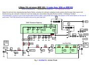
28/<str<strong>on</strong>g>70</str<strong>on</strong>g> <str<strong>on</strong>g>MHz</str<strong>on</strong>g> <str<strong>on</strong>g>Transverter</str<strong>on</strong>g> <str<strong>on</strong>g>–</str<strong>on</strong>g> <str<strong>on</strong>g>based</str<strong>on</strong>g> <strong>on</strong> <strong>DK7ZB</strong> <strong><strong>de</strong>sign</strong> <strong>for</strong> <strong>50</strong> <str<strong>on</strong>g>MHz</str<strong>on</strong>g><br />
by Julian Iredale, G8HCZ<br />
The circuit diagram is essentially the same as that <strong>de</strong>scribed in the files accompanying thiese<br />
notes. <strong>DK7ZB</strong> has <strong><strong>de</strong>sign</strong>ed a <strong>50</strong> <str<strong>on</strong>g>MHz</str<strong>on</strong>g> transverter <str<strong>on</strong>g>–</str<strong>on</strong>g> <strong>de</strong>tails in German here<br />
http://www.dk7zb.fox28.<strong>de</strong>/start1.htm<br />
there is also an English translati<strong>on</strong> at:<br />
http://www.qsl.net/dl5dbm/<br />
This is an excellent <strong><strong>de</strong>sign</strong> and I have been using this <strong>on</strong> 6m <strong>for</strong> some time. Having built a<br />
number of Me<strong>on</strong> transverters <strong>for</strong> <str<strong>on</strong>g>70</str<strong>on</strong>g> <str<strong>on</strong>g>MHz</str<strong>on</strong>g> I wanted to try and modify the <strong>DK7ZB</strong> <strong><strong>de</strong>sign</strong> <strong>for</strong> this<br />
band and compare its per<strong>for</strong>mance to the Me<strong>on</strong>.<br />
Modificati<strong>on</strong>s<br />
The main modificati<strong>on</strong>s are;<br />
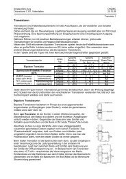
Oscillator<br />
This is a single 22 <str<strong>on</strong>g>MHz</str<strong>on</strong>g> oscillator in the original <strong><strong>de</strong>sign</strong> and I have modified this as shown<br />
below to give 42 <str<strong>on</strong>g>MHz</str<strong>on</strong>g> to mix with 28 <str<strong>on</strong>g>MHz</str<strong>on</strong>g> :
Linear<br />
The 2SC1302 linear does not have enough gain at <str<strong>on</strong>g>70</str<strong>on</strong>g> <str<strong>on</strong>g>MHz</str<strong>on</strong>g> and this has been replaced by the<br />
following:<br />
A final linear to give an output of about 10w was required and this has been ad<strong>de</strong>d as a<br />
<strong><strong>de</strong>sign</strong> from the VHF/UHF Dx book, using a BLW60 transistor as shown below;
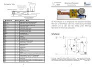
Antenna and power switching is per<strong>for</strong>med <strong>on</strong> a separate PCB as shown:<br />
Obviously tuned circuits have been re-scaled <strong>for</strong> <str<strong>on</strong>g>70</str<strong>on</strong>g> rather than <strong>50</strong> <str<strong>on</strong>g>MHz</str<strong>on</strong>g> throughout.<br />
The internals of the finished unit are shown below:
Clockwise from top left:<br />
Tx mixer, Oscillator and Rx mixer, Antenna and power switching, Final linear, driver linear.<br />
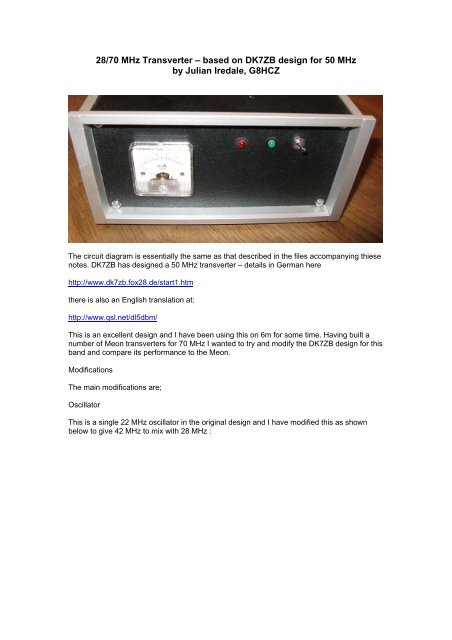
The fr<strong>on</strong>t panel (shown above has a meter to display power output <str<strong>on</strong>g>–</str<strong>on</strong>g> as in the original and full<br />
scale is approx 10w. there are LEDs to show power <strong>on</strong> (green) and Tx (red).<br />
The rear panel is shown below:<br />
From top LHS clockwise:<br />
PTT out (ph<strong>on</strong>o) to drive an external linear<br />
Rx input at 28 <str<strong>on</strong>g>MHz</str<strong>on</strong>g> (BNC)<br />
Tx input at 28 <str<strong>on</strong>g>MHz</str<strong>on</strong>g> (BNC)<br />
Antenna (N-type)<br />
Power input (4mm)
PTTin/power input (DIN)<br />
The ptt input is c<strong>on</strong>nected visa the 5-pin DIN socket and the power in can be either c<strong>on</strong>nected<br />
here or via the 4mm soclets/screw terminals.<br />
The DIN wiring is shown below (as viewed in the picture)<br />
Per<strong>for</strong>mance<br />
Rx<br />
On Rx the <str<strong>on</strong>g>Transverter</str<strong>on</strong>g> is in<strong>de</strong>stiguishable from the per<strong>for</strong>mance of the PW Me<strong>on</strong>. I can clearly<br />
read GB3BAA in tring and GB3RAL in Ox<strong>for</strong>d at all times. GB3ANG in Fife is variable<br />
<strong>de</strong>pending <strong>on</strong> c<strong>on</strong>diti<strong>on</strong>s. There is <strong>on</strong>e minor drawback <str<strong>on</strong>g>–</str<strong>on</strong>g> because thwe oscillator is tripled<br />
from 14 <str<strong>on</strong>g>MHz</str<strong>on</strong>g> to get 42 <str<strong>on</strong>g>MHz</str<strong>on</strong>g> there is a birdie at 28 <str<strong>on</strong>g>MHz</str<strong>on</strong>g> (14 x 2) and this obscures the beac<strong>on</strong><br />
at GB3BUX <strong>on</strong> <strong>50</strong>.000. Rx gain is sufficient and in practice an attenuator will be necessary<br />
with most transceivers to avoid a background S3 to s5.<br />
The transceiver needs to have separate Tx and Rx outputs. Most commercial transceivers<br />
either have this or can easily be modified to do so.<br />
Tx<br />
Approx 10w output is available <strong>for</strong> 0.5w drive from a suitable 28 Mhz transceiver. Linearity<br />
appears good.<br />
CAUTION <str<strong>on</strong>g>–</str<strong>on</strong>g> DO NOT USE MORE THAN 0.5W INPUT Otherwise damage may occur to the<br />
mixer.