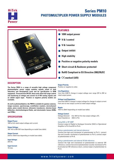
Series PM10 Photomultiplier Power Supply Modules ... - HiTek Power
Series PM10 Photomultiplier Power Supply Modules ... - HiTek Power
Series PM10 Photomultiplier Power Supply Modules ... - HiTek Power

You also want an ePaper? Increase the reach of your titles
YUMPU automatically turns print PDFs into web optimized ePapers that Google loves.
DESCRIPTION<br />
The <strong>Series</strong> <strong>PM10</strong> is a range of versatile high voltage component<br />
photomultiplier power supply modules equally suited to both<br />
laboratory and development work and for specification in OEM<br />
equipment. <strong>Power</strong>ed from 24V DC, these units allow full range control<br />
and monitoring of voltage and current via 0-10V analog signals and<br />
an inhibit signal input. Positive or negative polarity models are<br />
available.<br />
As well as photomultipliers, the <strong>PM10</strong> is suitable for gamma cameras,<br />
image scanners, spectroscopy, scintillation counters, microchannel<br />
plates, piezo crystal devices, ultrasonic transducers, electron beam<br />
deflection, electrorheological fluids, and electrostatic lenses (SEMs<br />
and STMs).<br />
SPECIFICATION<br />
Output <strong>Power</strong>:<br />
10W at full rated output voltage and current.<br />
Output Voltage:<br />
10V-1kV to 50V-5kV max depending on model (see table).<br />
Output Current:<br />
2mA to 10mA max depending on model (see table).<br />
Input Voltage:<br />
24V DC.<br />
Input Current:<br />
1A max.<br />
<strong>Series</strong> <strong>PM10</strong><br />
PHOTOMULTIPLIER POWER SUPPLY MODULES<br />
FEATURES<br />
10W output power<br />
V & I control<br />
V & I monitor<br />
Output inhibit<br />
High stability<br />
Positive or negative polarity models<br />
Short circuit & flashover protected<br />
RoHS Compliant to EU Directive 2002/95/EC<br />
marked (LVD)<br />
Output Polarity:<br />
Positive or negative to order.<br />
www.hitekpower.com<br />
Line Regulation:<br />
Less than 0.001% change in output voltage over range 22V to 26V at<br />
rated output power.<br />
Voltage Load Regulation:<br />
Less than 0.001% change in output voltage for change in output current<br />
from zero to max output current at rated output voltage.<br />
Ripple:<br />
10mV to 20mV depending on model (see table).<br />
Voltage Control:<br />
Voltage Demand: 0 to 10V for 0 to max output voltage ±2%.<br />
Input Impedance: 22kΩ (±1%).<br />
Using DAC or OP-AMP:<br />
Connect output of Digital to Analogue Converter (DAC) or Operational<br />
Amplifier to Pin 8 and 0V to Pin 6.<br />
Using a potentiometer and internal reference:<br />
Connect the high end (clockwise) of potentiometer to Pin 9, connect<br />
low end (counter clockwise) of potentiometer to Pin 6, connect wiper<br />
of potentiometer to Pin 8.<br />
Using a potentiometer and external 10 Volt reference:<br />
Connect the high end (clockwise) of potentiometer to external 10V<br />
reference, connect low end of potentiometer (counter clockwise) to Pin<br />
6 and external 10V reference return, connect wiper of potentiometer to<br />
Pin 8.
<strong>Series</strong> <strong>PM10</strong><br />
PHOTOMULTIPLIER POWER SUPPLY MODULES<br />
Using single fixed resistor:<br />
Connect a resistor between Pin 9 and Pin 8 using the internal impedance<br />
(22kΩ ±1%) as potential divider.<br />
Using two fixed resistors:<br />
Connect a resistor between Pin 9 and Pin 8, connect an additional<br />
resistor between Pin 8 and Pin 6.<br />
Note: Internal impedance 22kΩ (±1%).<br />
Current Control:<br />
Current Demand: 0 to 10V for 0 to max output current ±2%.<br />
Note: If left open, circuit supply assumes maximum<br />
current capability.<br />
Input Impedance: 1MΩ internal pull-up, to a +15V rail.<br />
Using DAC or OP-AMP:<br />
Connect output to Digital to Analogue Converter (DAC) or Operational<br />
Amplifier to Pin 4 and 0V to Pin 6.<br />
Using potentiometer and internal reference:<br />
Connect the high end (clockwise) of potentiometer to Pin 9, connect<br />
low end (counter clockwise) of potentiometer to Pin 6, connect wiper<br />
of potentiometer to Pin 4.<br />
Using potentiometer and external 10V reference:<br />
Connect the high end (clockwise) of potentiometer to external 10V<br />
reference, connect low end of potentiometer (counter clockwise) to Pin<br />
6 and external 10V reference return, connect wiper of potentiometer to<br />
Pin 4.<br />
Using two fixed resistors:<br />
Connect a resistor between Pin 9 and Pin 4, connect an additional<br />
resistor between Pin 4 and Pin 6.<br />
Monitors:<br />
Voltage Monitor: 0 to 10V ±2% or ±100mV, whichever is greater, for 0<br />
to rated output voltage.<br />
Output Impedance: 10KΩ ±1%.<br />
Current Monitor: 0 to 10V ±2% or ±100mV, whichever is greater, for 0<br />
to rated output current.<br />
Output Impedance: 10KΩ ±1%.<br />
Inhibit:<br />
Disable: 0 to 0.8V =OFF<br />
Enable: 2.2V to 24V =ON<br />
Open circuit =ON<br />
Stability:<br />
Less than 50ppm per hour at constant ambient temperature and rated<br />
output power after 1 hour warm-up.<br />
Temperature Coefficient:<br />
Less than 25ppm/oC at max output power.<br />
Operating Temperature:<br />
0oC to 50oC at up to 90% RH non-condensing.<br />
Storage Temperature:<br />
-35oC to +70oC.<br />
Altitude:<br />
Sea level to 2000 metres (6500 feet).<br />
Reliability:<br />
Mean Time Between Failure (MTBF) is greater than 100,000 hours. In<br />
accordance with MIL-HDBK-217F.<br />
Protection:<br />
The <strong>PM10</strong> is protected against continuous short circuit and flashover.<br />
Safety:<br />
Meets the requirements of the Low Voltage Directive, 73/23/EEC, by<br />
complying with BS EN60950 when installed as a component part of<br />
compliant equipment. Units are CE marked accordingly.<br />
RoHS:<br />
The <strong>Series</strong> <strong>PM10</strong> meets the requirements of EU Directive 2002/95/EC<br />
on the Restriction of use of certain Hazardous Substances in Electrical<br />
and Electronic Equipment (RoHS).<br />
Mechanical Specification:<br />
Dimensions: See outline drawing.<br />
Weight: <strong>PM10</strong>/102 & <strong>PM10</strong>/202: 0.4kg (0.88 lb)<br />
<strong>PM10</strong>/302 & <strong>PM10</strong>/502: 0.7kg (1.54 lb)<br />
Construction: Fabricated alloy with black painted finish.<br />
Earthing: Case internally connected to 0V.<br />
Output connection: 600mm long screened flying lead (see drawing).<br />
Output and Ordering Information:<br />
Model no Output<br />
Voltage<br />
Output<br />
Current<br />
Current<br />
Load<br />
Regulation<br />
Ripple<br />
pk-pk<br />
Output<br />
Stored<br />
Charge<br />
<strong>PM10</strong>/102* 10V-1kV 10mA 0.05% 10mV
<strong>Series</strong> <strong>PM10</strong><br />
PHOTOMULTIPLIER POWER SUPPLY MODULES<br />
Drawing dimensions are in mm (inches)<br />
Design developments may result in specification changes<br />
www.hitekpower.com<br />
These component power supplies meet the requirements of EC Directive 73/23/EEC (LVD).
<strong>Series</strong> <strong>PM10</strong><br />
PHOTOMULTIPLIER POWER SUPPLY MODULES<br />
Drawing dimensions are in mm (inches)<br />
Design developments may result in specification changes<br />
I MONITOR<br />
0V POWER<br />
0V SIGNAL<br />
V MONITOR<br />
0.7kg UNIT<br />
<strong>PM10</strong>/302<br />
<strong>PM10</strong>/502<br />
SERIES <strong>PM10</strong><br />
INHIBIT<br />
I CONTROL<br />
+24V INPUT<br />
+10V REF<br />
V CONTROL<br />
185 (7.28)<br />
172 (6.77)<br />
DIA 4 (0.16)<br />
41 (1.61)<br />
www.hitekpower.com<br />
70 (2.76)<br />
94 (3.70)<br />
41 (1.61)<br />
600 (23.62)
4/2011<br />
UK<br />
<strong>HiTek</strong> <strong>Power</strong> Ltd<br />
Hawthorn Road, Littlehampton<br />
West Sussex BN17 7LT<br />
UK<br />
Tel: +44 (0) 1903 712400<br />
Fax: +44 (0) 1903 712500<br />
e-mail: sales.uk@hitekpower.com<br />
GERMANY<br />
<strong>HiTek</strong> <strong>Power</strong> GmbH<br />
Joh.-Friedr.-Boettger-Str. 21<br />
D-63322 Roedermark<br />
Germany<br />
Tel: +49 (0) 6074 69285 0<br />
Fax: +49 (0) 6074 69285 10<br />
e-mail: sales.de@hitekpower.com<br />
www.hitekpower.com<br />
USA<br />
<strong>HiTek</strong> <strong>Power</strong> Inc<br />
124 Jewett Street, Unit #2<br />
Georgetown, MA 01833-1868<br />
USA<br />
Tel: +1 (978) 352-9100<br />
Fax: +1 (978) 352-9133<br />
e-mail: sales.us@hitekpower.com<br />
JAPAN<br />
<strong>HiTek</strong> <strong>Power</strong> Japan<br />
1-5-13 Kyutaroumachi<br />
Chou-ku, Osaka 541-0056<br />
Japan<br />
Tel: +81 (6) 6271 8180<br />
Fax: +81 (6) 6271 8190<br />
e-mail: info@hitekpowerjapan.co.jp