National Institute for Laser, Plasma, and Radiation Physics ... - IESL
National Institute for Laser, Plasma, and Radiation Physics ... - IESL
National Institute for Laser, Plasma, and Radiation Physics ... - IESL

You also want an ePaper? Increase the reach of your titles
YUMPU automatically turns print PDFs into web optimized ePapers that Google loves.
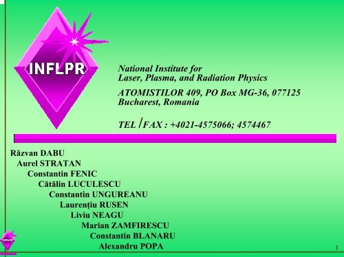
Răzvan DABU<br />
Aurel STRATAN<br />
Constantin FENIC<br />
Cătălin LUCULESCU<br />
Constantin UNGUREANU<br />
Laurenţiu RUSEN<br />
Liviu NEAGU<br />
Marian ZAMFIRESCU<br />
Constantin BLANARU<br />
Alex<strong>and</strong>ru POPA<br />
<strong>National</strong> <strong>Institute</strong> <strong>for</strong><br />
<strong>Laser</strong>, <strong>Plasma</strong>, <strong>and</strong> <strong>Radiation</strong> <strong>Physics</strong><br />
ATOMISTILOR 409, PO Box MG-36, 077125<br />
Bucharest, Romania<br />
TEL /FAX : +4021-4575066; 4574467<br />
1
<strong>National</strong> <strong>Institute</strong> <strong>for</strong> <strong>Laser</strong>s, <strong>Plasma</strong> <strong>and</strong> <strong>Radiation</strong> <strong>Physics</strong><br />
Bucharest, Romania<br />
Main role of NILPRP in the LASERACT project:<br />
-To develop the laser system with the specially required<br />
characteristics <strong>for</strong> the specific measuring techniques:<br />
shearography <strong>and</strong> holographic interferometry in digital<br />
version.<br />
-To provide expertise in custom laser devices.<br />
2
NILPRP activity in the workpackages (till MID-TERM REVIEW)<br />
Work description:<br />
W.P.1.1. Implementation of techniques.<br />
1.1.4. Definition of the operational parameters of the system.<br />
Deliverables:<br />
D2. Parameters of suitable laser-sensor design.<br />
Milestones:<br />
M1. Successful implementation of diagnostic procedure.<br />
3
WP 2.1. Laboratory prototype instrumentation<br />
Work description:<br />
Deliverables:<br />
Milestones:<br />
2.1.1 Laboratory prototype laser.<br />
2.1.2. Laboratory prototype multitask sensor.<br />
2.1.3. Laboratory prototype software.<br />
D9. Report of fundamental studies of system operation<br />
D10. Specification report on multitask recording with sensor/laser/ software laboratory<br />
prototype.<br />
D11.Technology implementation<br />
M3. Successful operation of the laboratory prototype.<br />
M4. Successful operation of the laboratory prototype to generate diagnostic in<strong>for</strong>mation<br />
M5. MID-TERM REVIEW<br />
-Successful development of a laser diagnostic technique<br />
-Successful implementation of a laboratory prototype.<br />
-Committed interest <strong>and</strong> strategic plans of partnership<br />
4
NILPRP participation in the technical meetings:<br />
1. Kick –off meeting, Iraklion, 27-30 March 2003.<br />
2. Technical Meeting, Ancona, 4-6 June 2003.<br />
3. Technical/review Meeting, Bucharest, 12-16 January 2004.<br />
4. Common experiments of shearography with BIAS, Bremen,<br />
30 June-6 July 2004.<br />
5. Common experiments (digital holography) with FORTH-<strong>IESL</strong><br />
<strong>and</strong> ProOptica), Iraklion, 26 July-1 August 2004.<br />
5
Required parameters of the laser source.<br />
<strong>Laser</strong> specifications according to the project proposal:<br />
1. <strong>Laser</strong> wavelength: 532 nm.<br />
2. <strong>Laser</strong> pulse duration: 2mJ.<br />
≥<br />
4. <strong>Laser</strong> pulse repetition rate: 1Hz.<br />
5. Coherence length: > 1m.<br />
6
Output beam parameters of the laser system presented in the<br />
technical/review Meeting Bucharest, January 2004, <strong>and</strong> used <strong>for</strong> common<br />
experiments in Bremen, June-July, <strong>and</strong> Iraklion, July 2004.<br />
1. <strong>Laser</strong> wavelength – 532 nm.<br />
2. <strong>Laser</strong> pulse duration - 8 nsec.<br />
3. Pulse energy - 2.3mJ.<br />
4. <strong>Laser</strong> pulse repetition rate - 0.5 – 5Hz , adjustable.<br />
5. Coherence length >1m.<br />
7
<strong>Laser</strong> system setup<br />
Fig.1.M 4 –M 5 , high reflecting mirrors at 1064 nm wavelength; YAG, Nd:YAG rod amplifier; Beam exp<strong>and</strong>er x 2.4; µ-<strong>Laser</strong>:<br />
ultra-compact diode pumped Q-switched microalser,1064 nm wavelength, 10 ns pulsewidth, 50µJ pulse energy,<br />
0-2 kHz adjustable pulse repetition rate, external trigger, coherence length >2m; KTP, doubling crystal 4 x 4 x 10 mm;<br />
M 6 – 7 , dichroic mirrors HR @ 532 nm, HT @ 1064 nm; α, return-angle of the amplifier path; D, dumper; *, front-panel connector;<br />
**, rear-panel connector; ATT, optical attenuators <strong>and</strong> green filter; PA, photocell preamplifier.<br />
8
A<br />
B<br />
Fig. 2.The intensity beam<br />
profile of the microlaser<br />
beam measured at the<br />
amplifier input<br />
Fig. 3. Temporal beam<br />
profile<br />
A: sample profile;<br />
B: averaged profile<br />
9
Fig. 4. Energy bar-graph of the microlaser output pulses.<br />
St<strong>and</strong>ard deviation ~ 0.71 %.<br />
10
Fig. 5. Histogram of the microlaser pulse energy.<br />
11
Fig.6. Energy bar-graph of the microlaser pulses measured at the non-pumped amplifier<br />
output. St<strong>and</strong>ard deviation ~ 2.7%.<br />
12
Fig.7. Histogram of the microlaser pulses measured at the non-pumped amplifier<br />
output.<br />
13
Fig.8.Bar-graph of the laser pulse energy at the amplifier output (23 J pump-<br />
energy) (a 3-dB- atenuation be<strong>for</strong>e energy detector). St<strong>and</strong>ard deviation ~ 3.7 %.<br />
- Pump energy restricted to 23 J in order to avoid parasitic feedback effects between<br />
the microlaser resonator <strong>and</strong> two pass amplifier (due to the lack of the optical<br />
isolation between microlaser <strong>and</strong> amplifier)<br />
14
Fig.9. Histogram of the pulse energy at the amplifier output (1064nm) (a 3-dBattenuation<br />
be<strong>for</strong>e energy detector).<br />
15
Fig.10. The bar-graph of the green pulse (532nm) energy.<br />
St<strong>and</strong>ard deviation ~ 25.1%.<br />
16
Fig.11. Histogram of the green pulse energy.<br />
17
Fig.12. Temporal profile of the green laser pulses.<br />
18
Fig.13. Near-field intensity profile (3D) of the green output pulse.<br />
19
Coherence length of the green laser<br />
We measured the coherence length of the green laser pulses using a Michelson interferometer set-up shown.<br />
As coherence length, we considered the path length difference <strong>for</strong> which fringe visibility V in<br />
the Michelson interferometer is reduced to ½:<br />
where I max , I min are related to the intensity of the interference fringe pattern.<br />
V>0.5 <strong>for</strong> path length difference of 176 cm<br />
max min ≥<br />
Fig. 14. Experimental set-up <strong>for</strong> coherence length evaluation<br />
µL, microlaser; M1, flat mirrors, HR @ 1064nm; KTP, doubling crystal, 4x4x10 mm;<br />
A, attenuator; M2-4, dichroic mirrors, HR @ 532 nm, HT @ 1064 nm ; BS,<br />
beam splitter (50,50) 532 nm; CCD, beam analyser camera.<br />
V<br />
=<br />
I<br />
I<br />
max<br />
− I<br />
+ I<br />
min<br />
0.<br />
5<br />
20
Fig.15. Interference fringe patterns acquired in 14-176 cm range of<br />
the path length difference.<br />
21
Drawbacks of the pulsed laser system used <strong>for</strong> common experiments in Bremen<br />
(July 2004) <strong>and</strong> Iraklion (July 2004):<br />
- Large fluctuations of the green output pulse energy (<strong>for</strong> both shearography<br />
<strong>and</strong> digital holography experiment).<br />
- Too small pulse energy <strong>for</strong> shearography experiments.<br />
- Under these conditions, software compensation of the pulse energy is required<br />
<strong>for</strong> both shearography <strong>and</strong> digital holography measurements.<br />
Targets:<br />
1. To increase the green pulse energy.<br />
2. To improve the stability of the green pulse energy.<br />
22
1. Reasons of small pulse energy:<br />
- Lack of optical isolation between microlaser <strong>and</strong> amplifier.<br />
Solution :<br />
- Faraday optical isolator between microlaser <strong>and</strong> amplifier.<br />
2. Reasons of green pulse energy fluctuations:<br />
- Intrinsic power instability of the microlaser output pulses, amplified during<br />
SHG process.<br />
- Diffraction effects that modulate the transverse intensity profile of the<br />
fundamental beam during the amplification process.<br />
- Parasitic feedback between the microlaser resonator, the amplifier stage <strong>and</strong><br />
KTP frequency doubler crystal.<br />
- The main cause:<br />
Intrinsic fluctuations of the polarization state of the microlaser.<br />
SOLUTION:<br />
- Saturation of the amplifier stage.<br />
23
Experimental set-up <strong>for</strong> measuring the fluctuation of the Polarization<br />
state of the microlaser.<br />
µ <strong>Laser</strong><br />
Glan Polarizer<br />
Energymeter<br />
24
Fig.16. Energy bar-graph of the microlaser output pulses without Glan polarizer.<br />
St<strong>and</strong>ard deviation ~ 4.3%.<br />
25
Fig.17. Energy bar-graph of the microlaser output pulses after Glan polarizer.<br />
26
Experimental setup <strong>for</strong> comparative measuring SHG pulse energy of a passively<br />
Q-switched microlaser <strong>and</strong> single-longitudinal mode acousto-optically<br />
Q-switched Crystalaser microlaser.<br />
L<br />
µ <strong>Laser</strong> KTP F Photocell<br />
Fig .18. Experimental setup <strong>for</strong> comparative study.<br />
L - plane convex lens, f = 100 mm<br />
KTP – 4x4x10 mm frequency doubler crystal<br />
F – filter (cut 1064nm)<br />
27
Comparative SHG pulse energy.<br />
Fig.19.A – Passively Cr:YAG Q-switched Nd:YAG microlaser.<br />
A<br />
28
Comparative SHG pulse energy.<br />
Fig.20. B –Single longitudinal mode, acoustoptically Q-switched Nd:YAG microlaser<br />
(Crystalaser).<br />
B<br />
29
<strong>Laser</strong> head set-up including Faraday Rotator<br />
Fig.21. Experimental setup including Faraday Rotator.<br />
M1 – M 5 , high reflecting mirrors at 1064 nm wavelength; YAG, Nd:YAG rod amplifier;<br />
KTP, doubling crystal; M 6 – 7 , dichroic mirrors HR @ 532 nm, HT @ 1064 nm;<br />
α, return-angle of the amplifier path; DL, divergent lens; PA, photocell preamplifier.<br />
30
Fig.22. Bar-graph of the microlaser pulse energy after Faraday Rotator.<br />
St<strong>and</strong>ard deviation ~ 23.6%.<br />
31
Fig.23. Average 1064 nm amplified pulse energy versus pump energy<br />
of the amplifier flash-lamp.<br />
32
Fig.24. Bar-graph of the amplified 1064 nm pulses <strong>for</strong> pulsed pump energy of 21 J,<br />
(10 dB attenuation be<strong>for</strong>e energy detector). St<strong>and</strong>ard deviation ~ 6.2 %.<br />
33
Fig.25. Bar-graph of the amplified 1064 nm pulses <strong>for</strong> pulsed pump energy of 25 J,<br />
(10 dB attenuation be<strong>for</strong>e energy detector). St<strong>and</strong>ard deviation ~ 4.4 %.<br />
34
Fig.26. Bar-graph of the amplified 1064 nm pulses <strong>for</strong> pulsed pump energy of 30 J,<br />
(10 dB attenuation be<strong>for</strong>e energy detector). St<strong>and</strong>ard deviation ~ 1.9 %.<br />
35
Fig.27. Bar-graph of the amplified 532 nm pulses <strong>for</strong> pulsed pump energy of 25 J,<br />
(Divergent lens was used).<br />
- Average energy (532 nm pulses) – 7.82 mJ<br />
- Std.Dev - 420µJ, ~ 5.4%.<br />
36
Fig.28. Histogram of the green pulses (532nm) <strong>for</strong> 25J pulsed pump<br />
energy. (Divergent lens was used). St<strong>and</strong>ard deviation ~ 5.4%.<br />
37
Fig.29. Bar-graph of the amplified 532 nm pulses <strong>for</strong> pulsed pump energy of 30 J,<br />
(Divergent lens was used).<br />
- Average energy (532 nm pulses) – 8.84 mJ<br />
- Std.Dev – 415 µJ, ~ 4.7%.<br />
38
Fig. 30. Histogram of the green pulses (532nm) <strong>for</strong> 30J pulsed pump<br />
energy (divergent lens was used). St<strong>and</strong>ard deviation ~ 4.7%.<br />
39
Fig.31. The output intensity beam profile of the 532 nm beam.<br />
40
Conclusions:<br />
Output parameter of the actual system:<br />
1. Wavelength: 532 nm<br />
2. Max. pulse energy: 9 mJ<br />
3. St<strong>and</strong>ard deviation: < 5 %<br />
4. Pulse duration : 8 nsec<br />
5. Repetition rate: Adjustable, max. 5Hz<br />
6. Coherence length : > 1.7 m<br />
Mode of operation:<br />
Green pulse energy adjustable by:<br />
- Pump energy (25-30J);<br />
- Optical attenuators at 532 nm (glass attenuators; λ/2 waveplate @ 532 nm<br />
<strong>and</strong> Glan polarizer);<br />
- <strong>Laser</strong> intensity modulator (crossed polarizers <strong>and</strong> electrooptical modulator)<br />
with transversal electric field, applied voltage controlled by computer.<br />
41