Laser Beam Expanders Basics and Applications - WinLens
Laser Beam Expanders Basics and Applications - WinLens
Laser Beam Expanders Basics and Applications - WinLens

Create successful ePaper yourself
Turn your PDF publications into a flip-book with our unique Google optimized e-Paper software.
<strong>Laser</strong> <strong>Beam</strong> <strong>Exp<strong>and</strong>ers</strong><br />
<strong>Basics</strong> <strong>and</strong> <strong>Applications</strong><br />
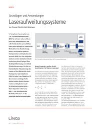
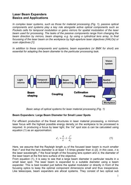
In complex laser systems, such as those for material processing (Fig. 1), passive optical<br />
components <strong>and</strong> systems play a key role alongside active optical components such as<br />
Pockels cells for temporal modulation or galvo mirrors for spatial modulation of the laser<br />
beam used for processing. The tasks of the passive components range from changing the<br />
beam direction by mirrors, beam shaping, e.g. by using a cylindrical lens array, to final<br />
focussing of the laser beam on the workpiece by high-aperture laser objectives (HALOs) or<br />
scan objectives [1].<br />
In addition to these components <strong>and</strong> systems, beam exp<strong>and</strong>ers (or BMX for short) are<br />
essential for adapting the beam diameter to the particular processing task.<br />
Light<br />
source<br />
<strong>Beam</strong><br />
shaping<br />
Temporal<br />
modulation<br />
Coupling<br />
Basic setup of optical systems for laser material processing (Fig. 1)<br />
<strong>Beam</strong> <strong>Exp<strong>and</strong>ers</strong>: Large <strong>Beam</strong> Diameter for Small <strong>Laser</strong> Spots<br />
For efficient production of the finest structures in laser material processing, a minimum<br />
laser focus with the highest possible energy density on the workpiece to be processed is<br />
required. In producing a focus by laser light, the 1/e 2 spot size df can be calculated using<br />
equation (1) as an approximation:<br />
d f<br />
<strong>Beam</strong><br />
delivering<br />
4<br />
≈ ⋅ λ ⋅<br />
π<br />
Here, we assume that the Rayleigh length zR of the focused laser beam is much smaller<br />
than f’ <strong>and</strong> that the lens diameter is at least 1.5 times greater than d1 [2]. In this case, λ is<br />
the laser wavelength, f’ the focal length of the focusing lens system <strong>and</strong> d1 the diameter of<br />
the laser beam at the first lens surface of the objective.<br />
From equation (1), it is easy to see that a large beam diameter in particular results in a<br />
small laser spot. The laser beam is exp<strong>and</strong>ed to a suitable diameter using a beam<br />
exp<strong>and</strong>er. This is best located just before the spatial modulator or directly in front of the<br />
focusing optics to keep the optimal component dimensions small <strong>and</strong> thus inexpensive.<br />
Like telescopes, beam exp<strong>and</strong>ers are afocal systems. They consist of two optical sub<br />
f<br />
d<br />
1<br />
'<br />
<strong>Beam</strong><br />
expansion<br />
Collimation<br />
Focusing<br />
Vision<br />
system<br />
Spatial<br />
modulation<br />
Workpiece<br />
(1)<br />
1
systems, the entrance <strong>and</strong> exit optics. Both sub systems are arranged so that the back<br />
focal point of the entrance optics F’in coincides with the front focal point of the exit optics<br />
Fout.<br />
The expansion ratio m as a quotient of the exit diameter Dout to the diameter of the nonexp<strong>and</strong>ed<br />
focused laser beam Din in front of the beam exp<strong>and</strong>er can be calculated using<br />
f’in as the focal length of the entrance optics <strong>and</strong> f’out as the focal length of the exit optics<br />
<strong>and</strong> with h=Din/2 <strong>and</strong> h’=Dout/2 as follows:<br />
m<br />
h'<br />
f '<br />
−<br />
out<br />
= − =<br />
(2)<br />
h f 'in<br />
Due to the general relation (3) between lateral expansion (expansion factor for afocal<br />
systems) m <strong>and</strong> angular magnification mang<br />
m ang<br />
1<br />
= (3)<br />
m<br />
a further effect can be easily derived for using beam exp<strong>and</strong>ers [3]: Divergences or<br />
collimation errors, which lie in the nature of the laser light source used or may have been<br />
introduced by the previous beam-shaping <strong>and</strong> delivering optics, are expressed as angular<br />
deviation of the rays that ideally travel parallel to the optical axis. Such errors prevent ideal<br />
focusing of the laser beams. For ray angles in object <strong>and</strong> image space, the following<br />
general relation applies to optical systems:<br />
m ang<br />
tanu'<br />
= (4)<br />
tanu<br />
where u is the angular error before <strong>and</strong> u’ the transferred angular error after expansion.<br />
For an expansion factor of m>I1I, all angular beam direction errors <strong>and</strong> beam divergences<br />
are thus reduced by the beam expansion factor!<br />
Basic Types of <strong>Beam</strong> <strong>Exp<strong>and</strong>ers</strong><br />
As with telescopes, there are two basic ways of implementing beam expansion systems:<br />
1.) The Kepler arrangement consisting of two positive lenses or groups of lenses<br />
2.) The Galileo configuration with a negative <strong>and</strong> a positive sub-system.<br />
The paraxial layouts of both configurations are illustrated in Figures 2 <strong>and</strong> 3.<br />
Kepler <strong>and</strong> Galileo beam exp<strong>and</strong>er systems (Figures 2 <strong>and</strong> 3)<br />
2
The real intermediate focus in the Kepler arrangement is advantageous for producing highgrade<br />
reference wave fronts with a homogeneous intensity (e.g., interferometry), because<br />
at the intermediate focal point, a pinhole can be positioned for spatial filtering.<br />
To use a powerful laser, e.g., for material processing, the Galileo type is preferred, as the<br />
tremendous power densities in the intermediate focus of the Kepler system can cause air<br />
breakdown. Using spatial filters is impossible in any case because of the high energy in<br />
the focal point.<br />
An additional general advantage of the Galileo arrangement is its reduced installation<br />
length L (see also Figures 3 <strong>and</strong> 4), which is approximately given by L=If’outI-If’inI,<br />
compared to the Kepler setup where L=If’outI+If’inI.<br />
Flexibility from Zoom <strong>and</strong> Modular Systems<br />
If particular flexibility is required, e.g., in the trial phase of a laser processing system,<br />
variable (zoom) beam exp<strong>and</strong>er systems are practical. Here, in the case of a beam<br />
exp<strong>and</strong>er system of the Galileo type, the negative entrance optics is typically split into two<br />
subgroups (e.g., positive <strong>and</strong> negative groups). By varying the distance e12 of both<br />
subgroups with their individual focal lengths f’1 <strong>and</strong> f’2, the total focal length f’in of these<br />
entrance optics can be adjusted according to equation (5):<br />
f '1<br />
f '2<br />
f 'in<br />
= (5)<br />
f ' + f ' −e<br />
By shifting the two groups with respect to the exit optics, it is possible to continuously vary<br />
the expansion factor. As in the case of photographic zoom lenses, a good compromise<br />
between image quality, expansion range <strong>and</strong> the engineering work entailed must be found<br />
when designing such a system.<br />
Figure 4 shows schematic paraxial setup of a variable 2x to 7x beam exp<strong>and</strong>er system.<br />
1<br />
Paraxial layout of a 2x-7x zoom beam exp<strong>and</strong>er (Figure 4)<br />
2<br />
12<br />
3
The relation between the individual focal lengths f’n, the lens distances en,n+1 <strong>and</strong> the<br />
expansion factor m is given by equations 6 <strong>and</strong> 7 [4] for paraxial expansion systems with<br />
three elements:<br />
e<br />
12<br />
f '1<br />
f '2<br />
= f ' 1+<br />
f '2<br />
+<br />
(6)<br />
f ' m<br />
<strong>and</strong><br />
f '<br />
e +<br />
3<br />
f '<br />
m<br />
1 2<br />
23 = f '2<br />
+ f '3<br />
(7)<br />
f '1<br />
If the spot size of the laser system needs to be adjusted only once for an application,<br />
modular beam exp<strong>and</strong>ers from LINOS are a suitable alternative. These beam exp<strong>and</strong>ers<br />
allow easy interchange of the smaller beam entrance lens (basic module) thanks to their<br />
modular design. Therefore, they enable the operator to easily adapt the expansion ratio of<br />
the system to new applications using just one beam exit element (basic module). The<br />
operator can choose from expansion ratios of 3x, 5x, 8x <strong>and</strong> 10x (Fig. 5). Each entrance<br />
unit, supporting a single expansion ratio, is optimised to match the basic module, thus<br />
guaranteeing optimal imaging quality. The focussing capability of the entrance element<br />
permits additional adjustment of the axial focus position <strong>and</strong> size beyond the following<br />
focussing lens system. The optics can be shifted without rotation during focussing, <strong>and</strong><br />
thus the required focusing stability is obtained.<br />
Modular beam exp<strong>and</strong>er from LINOS (Fig. 5)<br />
4
Wide waveb<strong>and</strong> exp<strong>and</strong>ers<br />
Any beam exp<strong>and</strong>er must introduce minimal wavefront distortion otherwise the post<br />
connected focusing lens will not be able to produce the smallest spot. <strong>Beam</strong> aberrations,<br />
such as spherical aberration make exact focusing difficult <strong>and</strong> the smallest spots<br />
impossible to obtain!<br />
Normally beam exp<strong>and</strong>ers are designed for a single wavelength, to simplify the optical<br />
design task. Indeed creating a wide b<strong>and</strong> beam exp<strong>and</strong>er adds a whole new dimension to<br />
the optical design task. But avoiding this extra work means that a new exp<strong>and</strong>er is usually<br />
required if the laser wavelength is changed.<br />
The innovative optical design of the LINOS BMX series now makes minimal wavefront<br />
distortion from 458nm to 1064nm a reality. Slight refocusing of the front lens is all that is<br />
needed if the wavelength is changed within this waveb<strong>and</strong>. The exceptionally broadb<strong>and</strong><br />
anti-reflection coating of the lenses support applications in the wavelength range of 458nm<br />
to 635nm (residual reflection less than 0.5%) <strong>and</strong> additionally at 1064nm (residual<br />
reflection less than 0.3%)<br />
Total transmission of a LINOS BMX expansion system (Fig. 6)<br />
Combination of high-grade materials <strong>and</strong> appealing design<br />
To enable the use of beam exp<strong>and</strong>er systems at high laser powers, the choice of materials<br />
for the individual optical components of the system is critical. Lenses, through which<br />
especially high-powered laser beams are focused, e.g., through small beam crosssections,<br />
should be manufactured from high-grade fused silica as this material exhibits a<br />
particularly high damage threshold. All other lenses used should also be made of glass<br />
that has the lowest possible absorption. The use of these kinds of materials in combination<br />
with high-grade coatings yields a laser resistance in LINOS BMX systems of more than<br />
100J/cm 2 at a laser pulse width of 20ns (S-O-1 measurement), e.g., for a laser wavelength<br />
of 1064nm.<br />
Last, but not least, LINOS beam exp<strong>and</strong>ers feature an appealing external design.<br />
5
Sources:<br />
1. T. Thöniß, S. Dreher, R. Schuhmann: >Photonik-Puzzle, optische<br />
Komponenten und Systeme für <strong>Laser</strong>anwendungen< (Photonics Puzzle,<br />
Optical Components <strong>and</strong> Systems for <strong>Laser</strong> <strong>Applications</strong>); <strong>Laser</strong>+Photonik 2<br />
(Juni 2003), pp. 14-21.<br />
2. W. Demtröder: ><strong>Laser</strong> SpectroscopyDie optische Abbildung< (The optical image); Geest & Portig,<br />
Leipzig 1980.<br />
4. F.-M- Chuang, M.-W. Chang : >Solution areas of three-component afocal<br />
zoom systems