PIERCE NUT INSTALLATION TOOLING
PIERCE NUT INSTALLATION TOOLING
PIERCE NUT INSTALLATION TOOLING

You also want an ePaper? Increase the reach of your titles
YUMPU automatically turns print PDFs into web optimized ePapers that Google loves.
<strong>PIERCE</strong> <strong>NUT</strong> <strong>INSTALLATION</strong> <strong>TOOLING</strong><br />
REEL-FEED ®<br />
AND BULK HEADS<br />
The total-service fastening<br />
systems company.<br />
®<br />
MULTIFASTENER<br />
®<br />
ISO 9001<br />
®<br />
Q S -9 0 0 0<br />
ISO 9001 ISO 14001<br />
T S-1 6 9 4 9
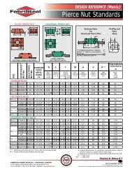
Installation Tooling<br />
Select the Pierce Nut that best meets your application requirements; then select the desired Head for either bulk or Strip Pierce Nut<br />
installation. Each Head locates the nut precisely within the die and, on each stroke of the press, drives a nut into the panel and securely<br />
locks it in place. All heads are rugged and proven dependable by years of service in the field. Choose the Installation Tooling that best suits<br />
YOUR needs. . .<br />
MULTI<strong>PIERCE</strong><br />
REEL-FEED HEAD<br />
MULTI<strong>PIERCE</strong> ® REEL-FEED ® AND BULK FEED HEADS<br />
MULTI<strong>PIERCE</strong> REEL-FEED HEAD<br />
The Multipierce Reel-Feed Head is designed for the efficient and<br />
economical installation of Strip Pierce ® Nuts. The Reel-Feed<br />
installation system consists of a reel of Pierce Nuts, a dereeler and<br />
Plastic Nut Guides — thereby eliminating the need for any bulk<br />
feeding equipment.<br />
2<br />
MULTI<strong>PIERCE</strong><br />
BULK FEED HEAD<br />
MULTI<strong>PIERCE</strong> BULK FEED HEAD<br />
The Multipierce Bulk Feed Head installs Bulk Pierce Nuts from<br />
gravity or power-feed devices. The Multipierce Bulk Feed Head, the<br />
original Pierce Nut installation Tool, has been field-proven over<br />
years of service to be accurate, efficient and durable.
MULTIMATIC<br />
REEL-FEED HEAD<br />
MULTIMATIC REEL-FEED AND BULK FEED HEADS<br />
MULTIMATIC REEL-FEED HEAD<br />
For controlled or programmed installation of Strip Pierce Nuts,<br />
specify Multifastener’s Multimatic Reel-Feed Head. This Head<br />
installs Strip Pierce Nuts with the same accuracy and consistency<br />
as our Bulk Multimatic Head, but eliminates the need for any bulk<br />
feeding equipment.<br />
3<br />
MULTIMATIC<br />
BULK FEED HEAD<br />
MULTIMATIC BULK FEED HEAD<br />
For controlled or programmed installation of Bulk Pierce Nuts,<br />
specify Multifastener’s Multimatic Head. Externally applied air<br />
pressure can either open or close the Multimatic Head, allowing<br />
varied nut patterns. The sequence of operation can be programmed<br />
and integrated into progressive dies, synchromatic<br />
transfer lines and other special applications.
Multipierce Reel-Feed ® Head<br />
BASE<br />
<strong>NUT</strong><br />
PLUNGER<br />
PROXIMITY<br />
PROBE<br />
NOSE<br />
OIL<br />
FEED PAWL<br />
UPPER DIE SHOE<br />
OPERATION<br />
Strip Pierce Nuts are fed through a Reel-Feed adaptor connected to<br />
the head assembly. The nuts are fed automatically into ready<br />
position. The press, when lowered, forces the plunger to drive the<br />
nut into the part, supported by a die button. The die button forms<br />
the part material into and around the Pierce Nut undercuts and/or<br />
clinches the nut corners, securing the nut in position.<br />
OPERATIONAL VIEW — MULTI<strong>PIERCE</strong> HEAD IN OPEN POSITION<br />
4<br />
CAM<br />
RESTRICTOR<br />
BACK-UP PLATE<br />
REEL FEED ADAPTOR<br />
FEED SPRING<br />
PRE-LOAD UNIT (MOVE FEED PAWL BACK ONE <strong>NUT</strong>) BY PULLING BACK KNOB.<br />
ORDERING INFORMATION:<br />
When ordering, specify:<br />
• Pierce Nut number<br />
• Length of Head extension (if any)<br />
• Alteration (if any)<br />
For applications requiring alterations to standard tooling, contact<br />
our Sales Department.<br />
PLASTIC <strong>NUT</strong> GUIDE<br />
STRIP<br />
<strong>PIERCE</strong><br />
<strong>NUT</strong>S<br />
DIE DESIGN INFORMATION<br />
• Other operations may be included in dies installing nuts.<br />
• Counterbore upper die shoe for shank and spring.<br />
• Part and nut sensing is suggested for most applications.<br />
• Show oil lines, fittings and manifolds for multiple Head installations<br />
on drawings.<br />
• If possible, position each Head to allow access to the proximity<br />
probe, oil hole on side of base and shank travel pin.<br />
• Allow room for entry of the Reel-Feed adaptor and Plastic Nut<br />
Guide. Arrange Head so Plastic Nut Guide does not interfere with<br />
press operation.<br />
• Piercing up from lower die shoe is possible; consult your<br />
representative for slug clearance hole requirements.<br />
• For all unique or special applications, consult your representative.
NOTE: METRIC DIMENSIONS SHOWN IN BOLD TYPE.<br />
MULTI<strong>PIERCE</strong> REEL-FEED HEAD DIMENSIONS<br />
PLAN VIEW<br />
Lc<br />
176.2 mm 6.94 in.<br />
<strong>NUT</strong><br />
142.2 mm<br />
5.60 in.<br />
60°<br />
66.7 mm<br />
2.63 in.<br />
FRONT VIEW SIDE VIEW<br />
Lc<br />
<strong>NUT</strong><br />
3.0 x 45°<br />
1/8 x 45°<br />
57.2 mm<br />
2.25 in.<br />
SHUT<br />
HEIGHT<br />
DIE SHOE SPRING<br />
POCKET COUNTERBORE<br />
D<br />
N †<br />
† See “Nose Plate<br />
Chart” below for dimensions.<br />
20.9 mm<br />
0.82 in. DIA.<br />
Lc<br />
<strong>NUT</strong><br />
53.8 mm 44.5 mm<br />
2.12 in. DIA. 1.75 in. DIA.<br />
SECTION AA<br />
HEAD MOUNTING DIMENSIONS FOR ALL <strong>PIERCE</strong> <strong>NUT</strong>S<br />
EXCEPT 32WM015, 99WM015 AND 20W1275<br />
(VIEW THRU DIE SHOE FROM TOP)<br />
7.8 mm<br />
0.31 in.<br />
19.1 mm<br />
0.750 in.<br />
<strong>NUT</strong> Lc<br />
15.9 mm<br />
0.625 in.<br />
11.1 mm<br />
0.4375 in. Lc<br />
<strong>NUT</strong><br />
45.2 mm<br />
1.78 in.<br />
B<br />
4.8 mm<br />
0.19 in.<br />
A A<br />
76.2 mm<br />
3.000 in.<br />
266.7 mm<br />
10.50 in. MAX<br />
284.0 mm<br />
11.18 in.<br />
E<br />
44.5 mm<br />
1.75 in.<br />
Note: 32WM015,<br />
99WM015 and<br />
20W1275<br />
dimensions<br />
shown in red<br />
FOR 10 Ø<br />
DWL 19 DP<br />
(2 HOLES)<br />
31.8 mm<br />
1.250 in.<br />
15.9 mm 0.625 in.<br />
M10 x 1.5 - 23<br />
(3 holes)<br />
44.47 mm<br />
1.751 in.<br />
5<br />
60, 61, 80, 12, 45, 22, AND 25 HI SERIES – HI STRESS <strong>PIERCE</strong> <strong>NUT</strong>S<br />
EXT.<br />
SHUT<br />
HEIGHT<br />
OPEN<br />
HEIGHT<br />
STROKE* B<br />
MM IN MM IN MM IN MM IN MM IN<br />
12.7 0.50 132.7 5.225 161.9 6.375 29.2 1.15 22.9 0.90<br />
38.1 1.50 158.1 6.225 212.7 8.375 54.6 2.15 48.3 1.90<br />
57.2 2.25 177.2 6.975 250.8 9.875 73.7 2.90 67.3 2.65<br />
20W1275 AND 32WM015 HI STRESS <strong>PIERCE</strong> <strong>NUT</strong>S<br />
EXT.<br />
SHUT<br />
HEIGHT<br />
OPEN<br />
HEIGHT<br />
STROKE* B<br />
MM IN MM IN MM IN MM IN MM IN<br />
12.7 0.50 132.7 5.225 161.9 6.375 29.2 1.15 20.8 0.82<br />
38.1 1.50 158.1 6.225 212.7 8.375 54.6 2.15 46.2 1.82<br />
57.2 2.25 177.2 6.975 250.8 9.875 73.7 2.90 65.2 2.57<br />
ALL UNIVERSAL <strong>PIERCE</strong> <strong>NUT</strong>S (EXCEPT 99WM015)<br />
EXT.<br />
SHUT<br />
HEIGHT<br />
OPEN<br />
HEIGHT<br />
STROKE* B<br />
MM IN MM IN MM IN MM IN MM IN<br />
12.7 0.50 130.2 5.125 161.9 6.375 31.8 1.25 22.9 0.90<br />
38.1 1.50 155.6 6.125 212.7 8.375 57.2 2.25 48.3 1.90<br />
57.2 2.25 174.6 6.875 250.8 9.875 76.2 3.00 67.3 2.65<br />
99WM015 UNIVERSAL <strong>PIERCE</strong> <strong>NUT</strong><br />
EXT.<br />
SHUT<br />
HEIGHT<br />
OPEN<br />
HEIGHT<br />
STROKE* B<br />
MM IN MM IN MM IN MM IN MM IN<br />
12.7 0.50 130.2 5.125 159.429.2 6.276 1.15 19.5 0.77<br />
38.1 1.50 155.6 6.125 210.2 8.276 54.6 2.15 44.9 1.77<br />
57.2 2.25 174.6 6.875 248.3 9.776 73.7 2.90 64.0 2.52<br />
EXTENSION D<br />
MM IN MM IN MM IN<br />
12.7 0.50 28.5 1.12<br />
38.1 1.50 53.8 2.12<br />
57.2 2.25 73.0 2.87<br />
Note: Metric Dimensions shown in bold type.<br />
*Difference between Open Height and Shut Height.<br />
49.3<br />
100.1<br />
138.2<br />
HEAD MOUNTING DIMENSIONS FOR<br />
32WM015, 99WM015 AND 20W1275<br />
(VIEW THRU DIE SHOE FROM TOP)<br />
14.27 mm<br />
0.562 in.<br />
<strong>NUT</strong> Lc<br />
20.64 mm 0.813 in.<br />
17.46 mm<br />
0.688 in. Lc<br />
<strong>NUT</strong><br />
NOSE PLATE CHART<br />
(using proximity probe nose plate)<br />
56.34 mm<br />
2.218 in.<br />
85.71 mm<br />
3.375 in.<br />
E<br />
1.94<br />
3.94<br />
5.44<br />
FOR Ø 10 mm DWL<br />
0.75 (19.0) DP<br />
(2 PLACES)<br />
41.26 mm<br />
1.625 in.<br />
20.64 mm 0.813 in.<br />
M10 x 1.5P THD<br />
0.88 (23.0) DP<br />
(3 PLACES)<br />
DIMENSIONS 60AW610 80AW825 20W1275 12WM508 45WM610 22WM825 25WM825 32WM015 13WM610 21WM610 37WM825 39WM825 50WM610 51WM610 99WM015 99WM1275<br />
N<br />
19.8 mm<br />
0.779 in.<br />
20.7 mm<br />
0.813 in.<br />
24.8 mm<br />
0.978 in.<br />
20.0 mm<br />
0.789 in.<br />
20.0 mm<br />
0.789 in.<br />
21.3 mm<br />
0.840 in.<br />
21.3 mm<br />
0.840 in.<br />
22.0 mm<br />
0.868 in.<br />
19.0 mm<br />
0.748 in.<br />
19.8 mm<br />
0.779 in.<br />
21.3 mm<br />
0.839 in.<br />
20.5 mm<br />
0.808 in.<br />
19.0 mm<br />
0.748 in.<br />
19.0 mm<br />
0.748 in.<br />
23.1 mm<br />
0.910 in.<br />
23.1 mm<br />
0.910 in.<br />
2N<br />
39.6 mm<br />
1.56 in.<br />
41.3 mm<br />
1.63 in.<br />
49.7 mm<br />
1.96 in.<br />
40.1 mm<br />
1.58 in.<br />
40.1 mm<br />
1.58 in.<br />
42.6 mm<br />
1.68 in.<br />
42.7 mm<br />
1.68 in.<br />
44.1 mm<br />
1.74 in.<br />
38.0 mm<br />
1.50 in.<br />
39.6 mm<br />
1.56 in.<br />
42.6 mm<br />
1.68 in.<br />
41.0 mm<br />
1.62 in.<br />
38.0 mm<br />
1.50 in.<br />
38.0 mm<br />
1.50 in.<br />
46.2 mm<br />
1.82 in.<br />
46.2 mm<br />
1.82 in.<br />
Note: Metric Dimensions shown in bold type.
Multimatic Reel-Feed ® Head<br />
BASE<br />
<strong>NUT</strong><br />
PLUNGER<br />
PROXIMITY<br />
PROBE<br />
NOSE<br />
AIR<br />
UPPER DIE SHOE<br />
FEED PAWL<br />
PRE-LOAD UNIT (MOVE FEED PAWL BACK ONE <strong>NUT</strong>) BY PULLING BACK KNOB.<br />
OPERATIONAL VIEW — MULTIMATIC HEAD IN OPEN POSITION<br />
OPERATION<br />
Strip Pierce Nuts are fed from nut reels, through a plastic nut guide,<br />
into the Reel-Feed Adaptor. Spring force, transmitted through a<br />
feed pawl in the Reel-Feed Adaptor, pushes the strip of nuts into<br />
position in the Head. The nut plunger shears off one nut at a time<br />
and installs it in the part. During the installation cycle, the cam on<br />
the base of the Head retracts the spring-powered feed pawl so that,<br />
on the upstroke, another nut is automatically fed into position<br />
under the plunger. The cycle repeats itself during each stroke of the<br />
press with Multipierce Heads, and “on command” with Multimatic<br />
Heads. SYSTEM COMPONENTS<br />
ORDERING INFORMATION:<br />
When ordering, specify:<br />
• Pierce Nut number<br />
• Length of Head extension (if any)<br />
• Alteration (if any)<br />
For applications requiring alterations to standard tooling, contact<br />
our Sales Department.<br />
6<br />
CAM<br />
RESTRICTOR<br />
BACK-UP PLATE<br />
P1<br />
FEED SPRING<br />
DIE DESIGN INFORMATION<br />
• Counterbore upper die shoe for cylinder cap and air supply line.<br />
• Position each Head to allow access to the proximity probe.<br />
• Punch support base is ported on both sides; cylinder cap may be<br />
rotated to allow air line connections to suit installation needs.<br />
• Air supply requirements: filter, pressure regulator @ 40 psi,<br />
lubrication unit, air line connections, solenoid valve (momentary<br />
type, 4-way, with no spring return) and part probe.<br />
In addition to the Multimatic Head, six basic components are<br />
required for system operation:<br />
PART PROBE: signals solenoid valve when panel is in proper<br />
position (to supply air pressure to open Head).<br />
ROTARY CAM LIMIT SWITCH: signals solenoid valve when press<br />
stroke is at 190 (to supply air pressure to close Head).<br />
FOUR-WAY SOLENOID VALVE: transfers air supply pressure to<br />
upper manifold to open Head (on signal from part probe) or to<br />
lower manifold to close Head (on signal from rotary cam limit<br />
switch).<br />
UPPER MANIFOLD: distributes air pressure to open Head.<br />
LOWER MANIFOLD: distributes air pressure to close Head.<br />
F-R-L UNIT: filters, regulates and lubricates air supply.<br />
P2<br />
HEAD<br />
TO<br />
OPEN<br />
TO<br />
CLOSE<br />
REEL FEED ADAPTOR<br />
PLASTIC <strong>NUT</strong> GUIDE<br />
AIR-FLOW<br />
DIRECTION*<br />
IN - P1<br />
OUT - P2<br />
IN - P2<br />
OUT - P1<br />
*USE 40 PSI AIR SUPPLY<br />
STRIP<br />
<strong>PIERCE</strong><br />
<strong>NUT</strong>S
A<br />
MULTIMATIC REEL-FEED HEAD DIMENSIONS<br />
PLAN VIEW<br />
Note: 32WM015,<br />
99WM015 and<br />
20W1275<br />
dimensions<br />
shown in green<br />
FRONT VIEW<br />
60°<br />
NOTE: METRIC DIMENSIONS SHOWN IN BOLD TYPE.<br />
85.9 mm<br />
3.38 in.<br />
Lc<br />
<strong>NUT</strong><br />
<strong>NUT</strong><br />
72.1 mm<br />
Lc<br />
2.837 in.<br />
28.4 mm 1.12 in.<br />
19.1 mm<br />
15.2 mm<br />
0.750 in.<br />
0.600 in.<br />
30.5 mm<br />
1.200 in. <strong>NUT</strong><br />
Lc<br />
28.6 mm<br />
1.125 in.<br />
69.9Ø mm<br />
2.75 in.<br />
To "A" Depth<br />
N †<br />
76.2 mm<br />
3.00 in.<br />
SHUT<br />
HEIGHT<br />
142.2 mm 5.60 in.<br />
176.2 mm 6.94 in.<br />
Lc<br />
<strong>NUT</strong><br />
Lc<br />
<strong>NUT</strong><br />
45.2 mm<br />
1.781 in. R0 3.0 mm<br />
0.12 in.<br />
95.3 mm<br />
3.750 in.<br />
FOR 10 Ø DWL<br />
19 DP<br />
(2 HOLES)<br />
31.8 mm<br />
1.250 in.<br />
;;;<br />
;;;<br />
;;;<br />
HEAD MOUNTING DIMENSIONS FOR ALL <strong>PIERCE</strong> <strong>NUT</strong>S<br />
EXCEPT 32WM015, 99WM015 AND 20W1275<br />
(VIEW THRU DIE SHOE FROM TOP)<br />
SYSTEM SCHEMATIC<br />
266.7 mm 10.50 in. MAX<br />
284.0 mm 11.18 in. MAX<br />
SIDE VIEW<br />
B<br />
15.9 mm<br />
0.625 in.<br />
M10 X 1.5 - 23<br />
DP THD<br />
(3 HOLES)<br />
;;;<br />
;;;<br />
;;;<br />
MANIFOLD KIT<br />
(MS-76-84, 1 per<br />
FOUR-WAY<br />
SOLENOID<br />
VALVE<br />
4 Heads required) EXHAUST<br />
44.5 mm<br />
1.75 in.<br />
S<br />
O L<br />
7<br />
EXT.<br />
SHUT<br />
HEIGHT<br />
OPEN<br />
HEIGHT<br />
STROKE* A B<br />
MM IN MM IN MM IN MM IN MM IN MM IN<br />
12.7 0.50 130.2 5.125 159.429.2 6.275 1.15 42.9 1.688 19.5 0.77<br />
38.1 1.50 155.6 6.125 210.2 8.275 54.6 2.15 68.2 2.688 44.9 1.77<br />
57.2 2.25 174.6 6.875 248.3 9.775 73.7 2.90 87.3 3.438 64.0 2.52<br />
Note: Metric Dimensions shown in bold type.<br />
*Difference between Open Height and Shut Height.<br />
†<br />
See “Nose Plate Chart” on page 5 for dimensions.<br />
FROM OTHER<br />
HEADS<br />
60, 61, 80, 12, 45, 22, AND 25 HI SERIES – HI STRESS <strong>PIERCE</strong> <strong>NUT</strong>S<br />
EXT.<br />
SHUT<br />
HEIGHT<br />
OPEN<br />
HEIGHT<br />
STROKE* A B<br />
MM IN MM IN MM IN MM IN MM IN MM IN<br />
12.7 0.50 132.7 5.225 161.9 6.375 29.2 1.15 42.8 1.687 22.9 0.90<br />
38.1 1.50 158.1 6.225 212.7 8.375 54.6 2.15 68.2 2.687 48.3 1.90<br />
57.2 2.25 177.2 6.975 250.8 9.875 73.7 2.90 87.3 3.437 67.3 2.65<br />
20W1275 AND 32WM015 HI STRESS <strong>PIERCE</strong> <strong>NUT</strong>S<br />
EXT.<br />
SHUT<br />
HEIGHT<br />
OPEN<br />
HEIGHT<br />
STROKE* A B<br />
MM IN MM IN MM IN MM IN MM IN MM IN<br />
12.7 0.50 132.7 5.225 161.9 6.375 29.2 1.15 42.9 1.688 20.8 0.82<br />
38.1 1.50 158.1 6.225 212.7 8.375 54.6 2.15 68.2 2.688 46.2 1.82<br />
57.2 2.25 177.2 6.975 250.8 9.875 73.7 2.90 87.3 3.438 65.2 2.57<br />
ALL UNIVERSAL <strong>PIERCE</strong> <strong>NUT</strong>S (EXCEPT 99WM015)<br />
EXT.<br />
SHUT<br />
HEIGHT<br />
OPEN<br />
HEIGHT<br />
STROKE* A B<br />
MM IN MM IN MM IN MM IN MM IN MM IN<br />
12.7 0.50 130.2 5.125 161.9 6.375 31.8 1.25 42.8 1.687 22.9 0.90<br />
38.1 1.50 155.6 6.125 212.7 8.375 57.2 2.25 68.2 2.687 48.3 1.90<br />
57.2 2.25 174.6 6.875 250.8 9.875 76.2 3.00 87.3 3.437 67.3 2.65<br />
99WM015 UNIVERSAL <strong>PIERCE</strong> <strong>NUT</strong><br />
HEAD MOUNTING DIMENSIONS FOR<br />
32WM015, 99WM015 AND 20W1275<br />
(VIEW THRU DIE SHOE FROM TOP)<br />
<strong>NUT</strong><br />
Lc<br />
85.71 mm<br />
3.375 in.<br />
R0 3.0 mm 0.12 in.<br />
17.46 mm<br />
0.688 in.<br />
19.1 mm<br />
0.750 in.<br />
34.93 mm<br />
1.375 in.<br />
33.32 mm<br />
1.313 in.<br />
<strong>NUT</strong><br />
Lc<br />
41.28 mm<br />
1.626 in.<br />
20.64 mm<br />
78.2Ø mm<br />
3.08 in.<br />
11.13 mm<br />
56.34 mm<br />
2.218 in.<br />
0.813 in.<br />
0.438 in.<br />
71.4 mm<br />
2.81 in.<br />
ROTARY CAM<br />
LIGHT SWITCH<br />
UPPER<br />
MANIFOLD<br />
LOWER<br />
MANIFOLD<br />
ELECTRICAL<br />
POWER SOURCE<br />
REGULATOR<br />
SHOP<br />
AIR<br />
FILTER LUBRICATOR<br />
S<br />
O<br />
L<br />
TO OTHER<br />
HEADS<br />
FOUR-WAY<br />
MULTIMATIC<br />
HEAD<br />
SET AT<br />
40 PSIG<br />
SOLENOID<br />
VALVE<br />
PART<br />
PROBE<br />
F-R-L UNIT<br />
ELECTRICAL POWER<br />
PANEL<br />
SOURCE<br />
NOTE: Parts shown in green are available through FabriSteel; other parts are provided by customer.<br />
FOR 10 Ø DWL<br />
19 DP<br />
(2 HOLES)<br />
M10 X 1.5 - 23<br />
DP THD<br />
(3 HOLES)
Multipierce and Multimatic Bulk Feed Heads<br />
BASE<br />
<strong>NUT</strong><br />
PLUNGER<br />
PROXIMITY<br />
PROBE<br />
NOSE<br />
AIR<br />
BASE<br />
<strong>NUT</strong><br />
PLUNGER<br />
PROXIMITY<br />
PROBE<br />
NOSE<br />
OPERATION<br />
Bulk Pierce Nuts are fed into a Multipierce or Multimatic Head<br />
through plastic nut guide from a gravity or power-feed device.<br />
Multipierce Bulk Feed Heads<br />
Constant pressure from the feeder, transmitted through the nuts,<br />
keeps a nut under the plunger when in the “open” or “ready”<br />
position. The press, when lowered, forces the plunger to drive the<br />
nut into the part, supported by a die button. The die button forms<br />
the part material into and around the Pierce Nut undercuts and/or<br />
clinches the nut corners, securing the nut in position.<br />
MULTI<strong>PIERCE</strong> MULTI<strong>PIERCE</strong> BULK BULK FEED FEED HEAD<br />
HEAD<br />
MULTIMATIC MULTIMATIC MULTIMATIC BULK BULK BULK FEED FEED FEED HEAD<br />
HEAD<br />
UPPER DIE SHOE<br />
CHUTE ATTACHING<br />
BLOCK ASSEMBLY<br />
ORDERING INFORMATION:<br />
When ordering, specify:<br />
• Pierce Nut number<br />
• Length of Head extension (if any)<br />
• Alteration (if any)<br />
For applications requiring alterations to standard tooling, contact<br />
our Sales Department.<br />
OIL<br />
BACK-UP PLATE<br />
BULK <strong>PIERCE</strong> <strong>NUT</strong>S PLASTIC <strong>NUT</strong> GUIDE<br />
OPERATIONAL VIEWS— BULK FEED HEADS IN OPEN POSITION<br />
8<br />
UPPER DIE SHOE<br />
CHUTE ATTACHING<br />
BLOCK ASSEMBLY<br />
P1<br />
BULK <strong>PIERCE</strong> <strong>NUT</strong>S<br />
BACK-UP PLATE<br />
P2<br />
PLASTIC <strong>NUT</strong> GUIDE<br />
HEAD<br />
TO<br />
OPEN<br />
TO<br />
CLOSE<br />
AIR-FLOW<br />
DIRECTION*<br />
IN - P1<br />
OUT - P2<br />
IN - P2<br />
OUT - P1<br />
*USE 40 PSI AIR SUPPLY<br />
Multimatic Bulk Feed Heads<br />
Force transmitted through the nuts in the plastic nut guide places a<br />
nut under the nut plunger in the “ready” position and, as the press<br />
cycles, the nut is installed. The plunger prevents a new nut from<br />
being placed into “ready” position until a signal is received from the<br />
part probe, at which time air forces the Head to an “open” position.<br />
Until a signal is received from the part probe the Head will remain<br />
in the “closed” position, preventing nuts from being placed in the<br />
“ready” position. This prevents double hits and potential damage to<br />
the die.<br />
DIE DESIGN INFORMATION<br />
• Multipierce and Multimatic Bulk Feed Heads are designed into a<br />
die in the same manner as Multipierce and Multimatic Reel-Feed<br />
Heads; same access requirements exist.<br />
• Refer to Multipierce and Multimatic sections for Head mounting<br />
dimensions.
A<br />
NOTE: METRIC DIMENSIONS SHOWN IN BOLD TYPE.<br />
60°<br />
60°<br />
FRONT VIEW<br />
Lc<br />
<strong>NUT</strong><br />
FRONT VIEW<br />
Lc<br />
<strong>NUT</strong><br />
57.2 mm<br />
2.250 in.<br />
N †<br />
28.6 mm<br />
1.125 in. <strong>NUT</strong><br />
Lc<br />
9.5 mm<br />
.375 in.<br />
SHUT<br />
HEIGHT<br />
76.2 mm<br />
3.00 in.<br />
N †<br />
38.1 mm<br />
1.50 in.<br />
9.5 mm<br />
.375 in.<br />
SHUT<br />
HEIGHT<br />
Lc<br />
<strong>NUT</strong><br />
MULTI<strong>PIERCE</strong> BULK FEED HEAD DIMENSIONS<br />
PLAN VIEW<br />
176.8 mm MAX<br />
6.96 in. MAX<br />
117.5 mm<br />
4.625 in.<br />
SIDE VIEW<br />
B<br />
6.35 mm<br />
0.25 in.<br />
MULTIMATIC BULK FEED HEAD DIMENSIONS<br />
PLAN VIEW<br />
117.5 mm<br />
4.625 in.<br />
Lc<br />
<strong>NUT</strong><br />
176.8 mm MAX<br />
9.65 in. MAX<br />
Lc<br />
<strong>NUT</strong><br />
SIDE VIEW<br />
B<br />
6.35 mm<br />
0.25 in.<br />
Lc<br />
Lc<br />
9<br />
ALL HI SERIES AND HI STRESS <strong>PIERCE</strong> <strong>NUT</strong>S<br />
EXT.<br />
SHUT<br />
HEIGHT<br />
OPEN<br />
HEIGHT<br />
STROKE* B<br />
MM IN MM IN MM IN MM IN MM IN<br />
12.7 0.50 132.7 5.225 161.9 6.375 29.2 1.15 25.4 1.00<br />
38.1 1.50 158.1 6.225 212.7 8.375 54.6 2.15 50.8 2.00<br />
57.2 2.25 177.2 6.975 250.8 9.875 73.7 2.90 69.9 2.75<br />
ALL UNIVERSAL <strong>PIERCE</strong> <strong>NUT</strong>S<br />
EXT.<br />
SHUT<br />
HEIGHT<br />
OPEN<br />
HEIGHT<br />
STROKE* B<br />
MM IN MM IN MM IN MM IN MM IN<br />
12.7 0.50 130.2 5.125 161.9 6.375 31.8 1.25 25.4 1.00<br />
38.1 1.50 155.6 6.125 212.7 8.375 57.2 2.25 50.8 2.00<br />
57.2 2.25 174.6 6.875 250.8 9.875 76.2 3.00 69.9 2.75<br />
* Difference between Open Height and Shut Height<br />
Note: Metric Dimensions shown in bold type.<br />
Note: Use shank and spring pocket info. on page 5.<br />
† See “Nose Plate Chart” on page 5 for dimensions.<br />
;;;<br />
;;;<br />
;;;<br />
;;;<br />
;;;<br />
;;;<br />
ALL HI SERIES AND HI STRESS <strong>PIERCE</strong> <strong>NUT</strong>S<br />
EXT.<br />
SHUT<br />
HEIGHT<br />
OPEN<br />
HEIGHT<br />
STROKE* A B<br />
MM IN MM IN MM IN MM IN MM IN MM IN<br />
12.7 0.50 132.7 5.225 161.9 6.375 29.2 1.15 42.8 1.687 25.4 1.00<br />
38.1 1.50 158.1 6.225 212.7 8.375 54.6 2.15 68.2 2.687 50.8 2.00<br />
57.2 2.25 177.2 6.975 250.8 9.875 73.7 2.90 87.3 3.437 69.9 2.75<br />
ALL UNIVERSAL <strong>PIERCE</strong> <strong>NUT</strong>S<br />
EXT.<br />
SHUT<br />
HEIGHT<br />
OPEN<br />
HEIGHT<br />
STROKE* A B<br />
MM IN MM IN MM IN MM IN MM IN MM IN<br />
12.7 0.50 130.2 5.125 161.9 6.375 31.8 1.25 42.8 1.687 25.4 1.00<br />
38.1 1.50 155.6 6.125 212.7 8.375 57.2 2.25 68.2 2.687 50.8 2.00<br />
57.2 2.25 174.6 6.875 250.8 9.875 76.2 3.00 87.3 3.437 69.9 2.75<br />
* Difference between Open Height and Shut Height<br />
Note: Metric Dimensions shown in bold type.<br />
Note: Use cylinder cap pocket info. on page 7.<br />
† See “Nose Plate Chart” on page 5 for dimensions.
<strong>NUT</strong> FLOW<br />
<strong>NUT</strong> FLOW<br />
Die Buttons<br />
The Die Button, held firmly in the die by the Retainer, forms the part material into and around the Pierce Nut and undercuts and/or clinches<br />
the nut corners to secure it in position. Additional die buttons, other than those shown below, are available for special applications. Consult<br />
your representative.<br />
44.5 mm<br />
1.750 in.<br />
44.5 mm<br />
1.750 in.<br />
A<br />
HI STRESS<br />
HSB SERIES<br />
A<br />
UNIVERSAL<br />
CORNER CLINCH<br />
MBR SERIES<br />
Die Button Retainers<br />
14.27 mm<br />
.562 in.<br />
25.4 mm<br />
1.00 in.<br />
B<br />
25.4 mm<br />
1.000 in.<br />
B<br />
3.175 mm<br />
.125 in.<br />
22.225 mm<br />
.875 in.<br />
HSRBAM/MPRAM – 100, 125<br />
31.75 mm<br />
1.250 in.<br />
41.28 mm<br />
1.625 in.<br />
76.2 mm<br />
3.00 in.<br />
44.5 mm<br />
1.750 in.<br />
A<br />
HI STRESS<br />
CORNER CLINCH<br />
HSR SERIES<br />
44.5 mm<br />
1.750 in.<br />
22.225 mm<br />
.875 in.<br />
63.50 mm<br />
2.50 in.<br />
22.225 mm<br />
.875 in.<br />
M10 screw x 40mm long<br />
M10 dowel x 40mm long<br />
6.35 mm<br />
.250 in.<br />
B<br />
25.4 mm<br />
1.000 in.<br />
A<br />
UNIVERSAL<br />
WATER SEAL<br />
MB SERIES<br />
“W” SERIES<br />
44.5 mm<br />
1.750 in.<br />
B<br />
X<br />
3.175 mm<br />
.125 in.<br />
22.225 mm<br />
.875 in.<br />
14.27 mm<br />
.562 in.<br />
25.4 mm<br />
1.00 in.<br />
<strong>NUT</strong> FLOW <strong>NUT</strong> FLOW<br />
A<br />
HI STRESS<br />
WATER SEAL<br />
"W" SERIES<br />
B<br />
25.4 mm<br />
1.000 in.<br />
44.5 mm<br />
1.750 in.<br />
44.5 mm<br />
1.750 in.<br />
A<br />
HSRBAM/MPRAM – 150<br />
31.75 mm<br />
1.250 in.<br />
41.28 mm<br />
1.625 in.<br />
76.2 mm<br />
3.00 in.<br />
B<br />
UNIVERSAL<br />
CORNER CLINCH<br />
MBR SERIES<br />
PRE-<strong>PIERCE</strong>D HOLE*<br />
10<br />
A<br />
HI STRESS<br />
CLOSE EDGE<br />
HSC SERIES<br />
3.175 mm<br />
.125 in.<br />
22.225 mm<br />
.875 in.<br />
B<br />
25.4 mm<br />
1.000 in.<br />
25.4 mm<br />
1.00 in.<br />
25.4 mm<br />
1.00 in.<br />
69.85 mm<br />
2.75 in.<br />
M10 screw x 40mm long<br />
M10 dowel x 40mm long<br />
6.35 mm<br />
.250 in.<br />
44.5 mm<br />
1.750 in.<br />
44.5 mm<br />
1.750 in.<br />
X<br />
A<br />
A<br />
UNIVERSAL<br />
MB SERIES<br />
B<br />
UNIVERSAL<br />
HEAVY METAL<br />
PRE-<strong>PIERCE</strong>D HOLE*<br />
B<br />
22.225 mm<br />
.875 in.<br />
SPECIFICATIONS<br />
RETAINER <strong>NUT</strong> TYPE X DIMENSION<br />
MPRAM-100<br />
HSRBAM-100<br />
MPRAM-125<br />
HSRBAM-125<br />
3.175 mm<br />
.125 in.<br />
22.225 mm<br />
.875 in.<br />
HSRBAM-150<br />
MPRAM-150<br />
<strong>PIERCE</strong><br />
<strong>NUT</strong> NO.<br />
60AW610<br />
80AW825<br />
20WM1275<br />
12WM610<br />
45WM610<br />
22WM825<br />
25WM825<br />
32WM015<br />
13M610<br />
50WM610<br />
51WM610<br />
21WM610<br />
37WM825<br />
39WM825<br />
99WM015<br />
99WM1275<br />
13M610, 50WM610,<br />
51WM610<br />
12WM610, 13M610,<br />
45WM610, 60AW610<br />
21WM610, 37WM825,<br />
39WM825<br />
22WM825, 25WM825,<br />
32WM015, 80AW825<br />
20WM1275<br />
99M1275<br />
A B<br />
25.4 mm<br />
1.00 in.<br />
31.75 mm<br />
1.25 in.<br />
38.10 mm<br />
1.50 in.<br />
25.4 mm<br />
1.00 in.<br />
25.4 mm<br />
1.00 in.<br />
31.75 mm<br />
1.25 in.<br />
31.75 mm<br />
1.25 in.<br />
31.75 mm<br />
1.25 in.<br />
25.4 mm<br />
1.00 in.<br />
25.4 mm<br />
1.00 in.<br />
25.4 mm<br />
1.00 in.<br />
31.75 mm<br />
1.25 in.<br />
31.75 mm<br />
1.25 in.<br />
31.75 mm<br />
1.25 in.<br />
38.10 mm<br />
1.50 in.<br />
38.10 mm<br />
1.50 in.<br />
Note: Metric Dimensions shown in bold type.<br />
23.80 mm<br />
0.937 in.<br />
30.15 mm<br />
1.187 in.<br />
36.49 mm<br />
1.437 in.<br />
23.80 mm<br />
0.937 in.<br />
23.80 mm<br />
0.937 in.<br />
30.15 mm<br />
1.187 in.<br />
30.15 mm<br />
1.187 in.<br />
30.15 mm<br />
1.187 in.<br />
23.80 mm<br />
0.937 in.<br />
23.80 mm<br />
.937 in.<br />
23.80 mm<br />
.937 in.<br />
30.15 mm<br />
1.187 in.<br />
30.15 mm<br />
1.187 in.<br />
30.15 mm<br />
1.187 in.<br />
36.49 mm<br />
1.437 in.<br />
36.49 mm<br />
1.437 in.<br />
47.6 mm 1.875 in.<br />
50.8 mm 2.00 in.<br />
47.6 mm 1.875 in.<br />
50.8 mm 2.00 in.<br />
50.8 mm 2.00 in.<br />
47.6 mm 1.875 in.
Part Design Guidelines<br />
HI-STRESS AND UNIVERSAL <strong>PIERCE</strong> <strong>NUT</strong>S<br />
Pierce Nuts are precision made, work hardened, high quality<br />
threaded fasteners that can be installed in sheet metal stampings<br />
by the same presses and the same dies used to form the part.<br />
Available in both strip and bulk form, Pierce Nuts pierce their own<br />
hole through a sheet metal panel, offering substantial savings in<br />
time and materials over other fasteners. Pierce Nuts are also<br />
available with non-threaded holes, ideal for thread forming screws.<br />
WHEN A FORMING OPERATION FOLLOWS<br />
A <strong>PIERCE</strong> <strong>NUT</strong> OPERATION.<br />
Do not form part closer than width of nut (W) when nut is installed<br />
as shown in “A”, below. By rotating nut 90 , as shown in “B”,<br />
distance “D” may be reduced to approximately 7 mm (1/4 in.).<br />
Tooling alterations are necessary to reduce “D” below 7 mm (1/4<br />
in.); consult your representative.<br />
SIMULPIERCING TWO SHEETS OF METAL.<br />
Total panel thickness is not to exceed 90% of recommended<br />
thickness for Pierce Nut metal range. For other panel materials,<br />
consult your representative.<br />
SEALING APPLICATIONS.<br />
Liquid-tight seals can be attained by use of a special die button.<br />
Consult your representative.<br />
<strong>NUT</strong> EDGE TO PANEL EDGE DISTANCE.<br />
W<br />
D<br />
<strong>NUT</strong><br />
LENGTH<br />
A<br />
B<br />
RADIAL POSITION OF <strong>PIERCE</strong> <strong>NUT</strong>S.<br />
When designing a part, the radial position of the Pierce Nut should<br />
be made optional whenever possible, to facilitate nut flow into die.<br />
APPLICATION IN SPECIAL MATERIALS.<br />
For HSLA, stainless steel, aluminum, or plastic material, consult<br />
your representative.<br />
DIRECTION OF ASSEMBLED LOAD.<br />
Assembled load must be against shoulders of nut.<br />
;;; ;; ; ; ;;<br />
DIRECTION OF LOAD<br />
T<br />
(METAL RANGE)<br />
1.5 mm OR LESS<br />
.060 in.<br />
1.6 mm OR MORE<br />
.061 in.<br />
T<br />
3.0<br />
2 x T<br />
W<br />
DIRECTION OF LOAD<br />
D<br />
D (MIN)<br />
MM IN<br />
0.12<br />
2 x T<br />
11<br />
EMBOSS REQUIREMENTS – UNIVERSAL <strong>PIERCE</strong> <strong>NUT</strong>S.<br />
When clamping two surfaces under load, the nut pilot must be<br />
recessed 0.25-0.38 mm (.010-.015 in.) from flush surface of panel,<br />
according to the following formula.<br />
“F” DIMENSION (PILOT HEIGHT) “F”<br />
MINUS “T” (METAL THICKNESS) “T”<br />
PLUS 0.38 mm +0.38 mm (.015 in.)<br />
EQUALS EMBOSS DEPTH “X”<br />
(Hi-Stress Nuts require no emboss.)<br />
F<br />
T<br />
<strong>NUT</strong> TO FLANGE DISTANCES (WITH STANDARD<br />
<strong>INSTALLATION</strong> <strong>TOOLING</strong>).<br />
Note: Closer nut-to-flange distances may be achieved using altered<br />
standard and/or special tooling. Consult your representative.<br />
N<br />
19.1 mm<br />
0.75 in.<br />
†<br />
MINIMUM <strong>NUT</strong> SPACING (WITH STANDARD <strong>INSTALLATION</strong><br />
<strong>TOOLING</strong>).<br />
Closer spacing may be achieved using altered standard and/or<br />
special tooling. Consult your representative.<br />
ALL<br />
<strong>NUT</strong><br />
SERIES<br />
NOTE: METRIC DIMENSIONS SHOWN IN BOLD TYPE.<br />
0.38 mm<br />
0.015 in.<br />
90°<br />
RAM<br />
MOUNTED<br />
DE-REELER<br />
(OPTIONAL)<br />
C*<br />
<strong>NUT</strong><br />
FLOW<br />
A<br />
B<br />
A B<br />
57.2 mm<br />
2.25 in.<br />
2N † 2N †<br />
MULTI<strong>PIERCE</strong> MULTIMATIC<br />
A B<br />
76.2 mm<br />
3.00 in.<br />
† See Nose Plate Chart on page 5 for dimensions.<br />
X<br />
<strong>INSTALLATION</strong><br />
HEAD ASSEMBLY<br />
<strong>NUT</strong><br />
DE-REELER<br />
DIE BUTTON<br />
& RETAINER<br />
28.4 mm<br />
1.12 in.<br />
28.4 mm<br />
1.12 in.<br />
RAM<br />
UPPER DIE SHOE<br />
LOWER DIE SHOE<br />
BOLSTER<br />
<strong>NUT</strong><br />
FLOW<br />
90°<br />
* Flat surface up to 69.6 mm (2.75 in.). If dimension exceeds 69.6 mm (2.75 in.)<br />
for Multipierce and Multimatic Heads, consult your representative.<br />
† See “Nose Plate Chart” on page 5 for dimensions.
“Good” and “Not Good” Registry Marker<br />
The Multifastener Registry Marker is designed to provide immediate visual determination of proper or improper ram setting by indicating if a<br />
press hit is not hard enough, too hard or just right.<br />
FUNCTION<br />
• The Registry Marker has a raised circle with the letters “N” and<br />
“G” located within, raised to different levels (see Fig. 2).<br />
• At the bottom of the die stroke, if a circle and a “G” are stamped<br />
in your metal panel, the die is set properly (see Fig. 1).<br />
• If a circle and “NG” appears, the hit is too hard (see Fig. 1).<br />
• If no mark appears, the hit is too light (see Fig. 1).<br />
LOCATION IN THE DIE<br />
N<br />
G<br />
Too Hard<br />
BALL<br />
LOCK<br />
13.0 mm<br />
.512 in.<br />
N<br />
G<br />
A<br />
PART NO.<br />
DIMENSION<br />
MSM-26-30<br />
TO LETTER<br />
76.20 mm<br />
"G"<br />
3.000 in.<br />
A AND CIRCLE<br />
TO LETTER 75.95 mm<br />
"N" 2.990 in.<br />
FIGURE 2.<br />
The Registry Marker is mounted in the same die shoe as the<br />
Installation Head and is positioned over the part panel that is to<br />
receive the Pierce Nut (see Fig. 3).<br />
SETTING<br />
The Registry Marker is available in one standard length: 76.07mm<br />
(2.995 in.).<br />
MOUNTING IN THE DIE<br />
G<br />
Just Right<br />
SHUT<br />
HEIGHT<br />
UPPER<br />
DIE SHOE<br />
BALL LOCK<br />
RETAINER<br />
REGISTRY<br />
MARKER<br />
PART<br />
The Registry Marker incorporates a Light Duty ball lock feature to<br />
facilitate mounting in the die.<br />
Too Light<br />
LOWER<br />
DIE SHOE<br />
ADDITIONAL INFORMATION<br />
Inch Registry Markers are available. Heavy-duty ball lock Registry<br />
Markers also available: Inch MS-26-30-HD, Metric MSM-26-30-HD<br />
FIGURE 1.<br />
FIGURE 3.<br />
NOTE: METRIC DIMENSIONS SHOWN IN BOLD TYPE.<br />
Set-Up and Alignment Procedures<br />
Please contact Multifastener for specific CAD data on the Multipierce or Multimatic Head assemblies and the specific CAD data on the Die<br />
Button Retainers. CAD data provided will give you screw and dowel locations for mounting both the Head Assemblies and Die Button Retainers.<br />
Alignment buttons are available for Direct Layout or Die Layout method of alignment. The alignment button can also be used to verify proper<br />
alignment of the tooling in the die.<br />
DIRECT LAYOUT METHOD<br />
• Install die button retainer by direct layout or with template.<br />
• Insert alignment die button in retainer.<br />
• Invert die set (so die button retainer is on top).<br />
• Set base, back-up plate, and plunger in head position.<br />
• Lower die shoe (with retainer) so plunger enters die button.<br />
Plunger Plunger Plunger Plunger Plunger and and and and and die die die die die button button button button button must must must must must be be be be be equivalent equivalent equivalent equivalent equivalent sizes. sizes. sizes. sizes. sizes.<br />
• Transfer base mounting holes to die (with punch).<br />
• Repeat steps above for all Heads in die.<br />
• Drill and tap mounting holes for screws.<br />
• Loosely mount base and back-up plate in each Head location.<br />
• Replace mating die shoe.<br />
• Lower die shoe (with retainer) so plunger enters die button.<br />
• Tighten base mounting screws.<br />
• Repeat steps above for each Head in die.<br />
• Remove mating die shoe; transfer dowel holes. Drill as<br />
required for reaming.<br />
• Ream for press fit for dowel pins.<br />
• Locate and machine clearance holes for shank and spring.<br />
• Install Head in each Head location. Follow plant die tryout<br />
procedures; follow Multifastener ram setting procedures in<br />
this manual.<br />
DIE LAYOUT METHOD<br />
• Install die button retainer by direct layout or with template.<br />
Insert alignment die button in retainer.<br />
12<br />
• Loosely mount base,<br />
back-up plate, and<br />
plunger in each Head<br />
location by die layout<br />
procedure.<br />
• Lower die shoe<br />
with retainer so<br />
plunger properly<br />
enters die button.<br />
• Tighten base<br />
mounting screws.<br />
• Repeat steps<br />
above for each<br />
Head in die.<br />
• Remove mating<br />
die shoe; transfer<br />
dowel holes. Drill<br />
as required for<br />
reaming.<br />
• Ream for press fit<br />
for dowel pins.<br />
• Locate and<br />
BASE<br />
BACKUP<br />
PLATE<br />
;;<br />
;;;<br />
;; ; ;; ;; ;<br />
;; ; ;; ;<br />
;;;<br />
BOTTOM<br />
DIE SHOE<br />
RETAINER<br />
ALIGNMENT<br />
DIE BUTTON<br />
TOP<br />
DIE SHOE<br />
<strong>NUT</strong><br />
PLUNGER<br />
machine clearance holes for shank and spring.<br />
• Install Head in each Head location. Follow plant die tryout<br />
procedures; follow ram setting procedures in this manual.
HI<br />
HS<br />
UP<br />
Tooling Standards<br />
METRIC DIMENSIONS<br />
<strong>PIERCE</strong> <strong>NUT</strong><br />
NUMBER<br />
60AWM610<br />
61WM610<br />
80AWM825<br />
20WM1275<br />
12M610<br />
12WM610<br />
45WM610<br />
22M825<br />
22WM825<br />
25M825<br />
25WM825<br />
32M015<br />
32WM015<br />
21M610<br />
21WM610<br />
37M825<br />
37WM825<br />
39M825<br />
39WM825<br />
50WM610<br />
51M610<br />
51WM610<br />
99M015<br />
99WM015<br />
<strong>PIERCE</strong> METAL<br />
RANGE*<br />
MILLIMETERS<br />
0.64-1.16<br />
1.17-1.46<br />
1.47-1.65<br />
0.60-1.15<br />
1.16-1.60<br />
1.40-2.15<br />
2.16-2.80<br />
0.64-1.16<br />
1.17-1.69<br />
1.70-2.29<br />
.067-2.29+<br />
0.64-1.16<br />
1.17-1.69<br />
1.70-2.29<br />
.067-2.29+<br />
0.64-1.01<br />
1.02-1.41<br />
1.42-2.21<br />
0.64-1.31<br />
1.32-2.15<br />
2.16-2.69<br />
0.64-1.31<br />
1.32-1.84<br />
1.85-2.15<br />
2.16-2.69<br />
0.64-0.80<br />
0.81-1.36<br />
1.37-1.68<br />
1.27-1.74<br />
1.75-2.15<br />
2.16-3.56<br />
<strong>INSTALLATION</strong><br />
LOAD-KN<br />
72<br />
81<br />
89<br />
72<br />
98<br />
143<br />
174<br />
54<br />
81<br />
107<br />
72<br />
98<br />
134<br />
27<br />
36<br />
63<br />
45<br />
72<br />
89<br />
36<br />
54<br />
63<br />
81<br />
18<br />
32<br />
36<br />
72<br />
89<br />
143<br />
DIE BUTTON<br />
PART NUMBER<br />
HSB-60A-030-R<br />
HSB-60A-060-R<br />
HSB-60A-065-R<br />
1.40-2.20 81 HSB-61-080-R<br />
HSR-80-045-R<br />
HSB-80-060-R<br />
HSB-120-060-R<br />
HSB-120-095-R<br />
HSR-12-045-R<br />
HSB-12-060-R<br />
HSB-12-090-R<br />
HSC-12-090-R<br />
1.40-2.79 161 HSB-12-090-R<br />
HSR-22-045-R<br />
HSB-22-060-R<br />
HSR-22/25-060/090-R<br />
HSC-22/25-090-R<br />
1.40-2.79 161 HSR-22/25-060/090-R<br />
1.02-2.29 161 HSB-32-060-R<br />
0.64-0.80<br />
0.81-1.36<br />
18<br />
32<br />
MBR-21-039-R<br />
MB-21-050-R<br />
MB-21-075-R<br />
MBR-37-051-R<br />
MB-37-060/075-R<br />
MB-37-090-R<br />
MBR-39-051-R<br />
MB-39-065-R<br />
MB-39-075-R<br />
MB-39-090-R<br />
MBR-50-031-R<br />
MB-50-040-R<br />
MBR-51-031-R<br />
MB-51-040-R<br />
MB-51-060-R<br />
MBR-99-068-R<br />
MB-99-075-R<br />
MB-99-120-R<br />
*Consult your representative for installation recommendations outside these metal ranges.<br />
**See pages 5, 7, and 9 for available nose extensions and other dimensional information.<br />
13<br />
RETAINER<br />
PART NUMBER<br />
HSRBAM-100<br />
HSRBAM-100<br />
HSRBAM-125<br />
HSRBAM-150<br />
HSRBAM-100<br />
HSRBAM-100<br />
HSRBAM-125<br />
HSRBAM-125<br />
HSRBAM-125<br />
MPRAM-125<br />
MPRAM-125<br />
MPRAM-125<br />
MPRAM-100<br />
MPRAM-100<br />
MPRAM-150<br />
BULK<br />
MULTI<strong>PIERCE</strong>/<br />
MULTIMATIC<br />
HEAD ASSEMBLY<br />
PART NUMBER**<br />
HSSM-60-PNPT00-50<br />
MMSM-60-PNPT00-50<br />
HSSM-61-PNPT00-50<br />
MMSM-61-PNPT00-50<br />
HSSM-80-PNPT00-50<br />
MMSM-80-PNPT00-50<br />
HSSM-120-PNPT00-50<br />
MMSM-120-PNPT00-50<br />
HSSM-12-PNPT00-50<br />
MMSM-12-PNPT00-50<br />
HSSM-12-PNPT00-50<br />
MMSM-12-PNPT00-50<br />
HSSM-22/25-PNPT00-50<br />
MMSM-22/25-PNPT00-50<br />
HSSM-22/25-PNPT00-50<br />
MMSM-22/25-PNPT00-50<br />
HSSM-32-PNPT00-50<br />
MMSM-32-PNPT00-50<br />
MPSM-21-PNPT00-50<br />
MMSM-21-PNPT00-50<br />
MPSM-37-PNPT00-50<br />
MMSM-37-PNPT00-50<br />
MPSM-39-PNPT00-50<br />
MMSM-39-PNPT00-50<br />
MPSM-50-PNPT00-50<br />
MMSM-50-PNPT00-50<br />
MPSM-51-PNPT00-50<br />
MMSM-51-PNPT00-50<br />
MPSM-99-PNPT00-50<br />
MMSM-99-PNPT00-50<br />
REEL-FEED<br />
MULTI<strong>PIERCE</strong>/<br />
MULTIMATIC<br />
HEAD ASSEMBLY<br />
PART NUMBER**<br />
HSNCM-60-PNPT00-50<br />
MMNCM-60-PNPT00-50<br />
HSNCM-61-PNPT00-50<br />
MMNCM-61-PNPT00-50<br />
HSNCM-80-PNPT00-50<br />
MMNCM-80-PNPT00-50<br />
HSNSM-120-PNPT00-50<br />
MMNSM-120-PNPT00-50<br />
HSNCM-12-PNPT00-50<br />
MMNCM-12-PNPT00-50<br />
HSNCM-12-PNPT00-50<br />
MMNCM-12-PNPT00-50<br />
HSNCM-22/25-PNPT00-50<br />
MMNCM-22/25-PNPT00-50<br />
HSNCM-22/25-PNPT00-50<br />
MMNCM-22/25-PNPT00-50<br />
HSNSM-32-PNPT00-50<br />
MMNSM-32-PNPT00-50<br />
MPNCM-21-PNPT00-50<br />
MMNCM-21-PNPT00-50<br />
MPNCM-37-PNPT00-50<br />
MMNCM-37-PNPT00-50<br />
MPNCM-39-PNPT00-50<br />
MMNCM-39-PNPT00-50<br />
MPNCM-50-PNPT00-50<br />
MMNCM-50-PNPT00-50<br />
MPNCM-51-PNPT00-50<br />
MMNCM-51-PNPT00-50<br />
MPNSM-99-PNPT00-50<br />
MMNSM-99-PNPT00-50
HI<br />
HS<br />
UP<br />
INCH DIMENSIONS<br />
<strong>PIERCE</strong> <strong>NUT</strong><br />
NUMBER<br />
60E420<br />
60WE420<br />
61WE420<br />
80E618<br />
80WE618<br />
20WE1213<br />
12E420<br />
12WE420<br />
45WE420<br />
22E618<br />
22WE618<br />
25E618<br />
25WE618<br />
32E816<br />
32WE816<br />
21E420<br />
21WE420<br />
37E618<br />
37WE618<br />
39E618<br />
39WE618<br />
50WE420<br />
51E420<br />
51WE420<br />
99E816<br />
99WE816<br />
<strong>PIERCE</strong> METAL<br />
RANGE*<br />
INCHES<br />
.025-.045<br />
.046-.057<br />
.058-.065<br />
.024-.045<br />
.045-.063<br />
.055-.085<br />
.085-.110<br />
.025-.045<br />
.046-.066<br />
.067-.090<br />
.067-.090+<br />
.055-.110<br />
.025-.045<br />
.046-.066<br />
.067-.090<br />
.067-.090+<br />
.055-.110<br />
.040-.090<br />
.025-.039<br />
.040-.055<br />
.056-.087<br />
.025-.051<br />
.052-.084<br />
.085-.106<br />
.025-.051<br />
.052-.072<br />
.073-.084<br />
.085-.106<br />
.025-.031<br />
.032-.053<br />
.054-.066<br />
.050-.068<br />
.069-.084<br />
.085-.140<br />
<strong>INSTALLATION</strong><br />
LOAD-TONS<br />
8<br />
9<br />
10<br />
8<br />
11<br />
16<br />
19.5<br />
6<br />
9<br />
12<br />
18<br />
8<br />
11<br />
15<br />
18<br />
18<br />
*Contact your representative for installation recommendations outside these metal ranges.<br />
**See pages 5, 7, and 9 for available nose extensions and other dimensional information.<br />
3<br />
4<br />
7<br />
5<br />
8<br />
10<br />
4<br />
6<br />
7<br />
9<br />
2<br />
3.5<br />
4<br />
8<br />
10<br />
16<br />
DIE BUTTON<br />
PART NUMBER<br />
HSB-60A-030-R<br />
HSR-60A-045-R<br />
HSB-60A-060-R<br />
.055-.087 9 HSB-61-080-R<br />
.025-.031<br />
.032-.053<br />
2<br />
3.5<br />
HSR-80-045-R<br />
HSB-80-060-R<br />
HSB-120-060-R<br />
HSB-120-095-R<br />
HSR-12-045-R<br />
HSB-12-060-R<br />
HSB-12-090-R<br />
HSC-12-090-R<br />
HSB-12-090-R<br />
HSR-22-045-R<br />
HSB-22-060-R<br />
HSR-22/25-060/090-R<br />
HSC-22/25-090-R<br />
HSR-22/25-060/090-R<br />
HSB-32-060-R<br />
MBR-21-039-R<br />
MB-21-050-R<br />
MB-21-075-R<br />
MBR-37-051-R<br />
MB-37-060/075-R<br />
MB-37-090-R<br />
MBR-39-051-R<br />
MB-39-065-R<br />
MB-39-075-R<br />
MB-39-090-R<br />
MBR-50-031-R<br />
MB-50-040-R<br />
MBR-51-031-R<br />
MB-51-040-R<br />
MB-51-060-R<br />
MBR-99-068-R<br />
MB-99-075-R<br />
MB-99-120-R<br />
14<br />
RETAINER<br />
PART NUMBER<br />
HSRBAM-100<br />
HSRBAM-100<br />
HSRBAM-125<br />
HSRBAM-150<br />
HSRBAM-100<br />
HSRBAM-100<br />
HSRBAM-125<br />
HSRBAM-125<br />
HSRBAM-125<br />
MPRAM-125<br />
MPRAM-125<br />
MPRAM-125<br />
MPRAM-100<br />
MPRAM-100<br />
MPRAM-150<br />
BULK<br />
MULTI<strong>PIERCE</strong>/<br />
MULTIMATIC<br />
HEAD ASSEMBLY<br />
PART NUMBER**<br />
HSSM-60-PNPT00-50<br />
MMSM-60-PNPT00-50<br />
HSSM-61-PNPT00-50<br />
MMSM-61-PNPT00-50<br />
HSSM-80-PNPT00-50<br />
MMSM-80-PNPT00-50<br />
HSSM-120-PNPT00-50<br />
MMSM-120-PNPT00-50<br />
HSSM-12-PNPT00-50<br />
MMSM-12-PNPT00-50<br />
HSSM-12-PNPT00-50<br />
MMSM-12-PNPT00-50<br />
HSSM-22/25-PNPT00-50<br />
MMSM-22/25-PNPT00-50<br />
HSSM-22/25-PNPT00-50<br />
MMSM-22/25-PNPT00-50<br />
HSSM-32-PNPT00-50<br />
MMSM-32-PNPT00-50<br />
MPSM-21-PNPT00-50<br />
MMSM-21-PNPT00-50<br />
MPSM-37-PNPT00-50<br />
MMSM-37-PNPT00-50<br />
MPSM-39-PNPT00-50<br />
MMSM-39-PNPT00-50<br />
MPSM-50-PNPT00-50<br />
MMSM-50-PNPT00-50<br />
MPSM-51-PNPT00-50<br />
MMSM-51-PNPT00-50<br />
MPSM-99-PNPT00-50<br />
MMSM-99-PNPT00-50<br />
REEL-FEED<br />
MULTI<strong>PIERCE</strong>/<br />
MULTIMATIC<br />
HEAD ASSEMBLY<br />
PART NUMBER**<br />
HSNCM-60-PNPT00-50<br />
MMNCM-60-PNPT00-50<br />
HSNCM-61-PNPT00-50<br />
MMNCM-61-PNPT00-50<br />
HSNCM-80-PNPT00-50<br />
MMNCM-80-PNPT00-50<br />
HSNSM-120-PNPT00-50<br />
MMNSM-120-PNPT00-50<br />
HSNCM-12-PNPT00-50<br />
MMNCM-12-PNPT00-50<br />
HSNCM-12-PNPT00-50<br />
MMNCM-12-PNPT00-50<br />
HSNCM-22/25-PNPT00-50<br />
MMNCM-22/25-PNPT00-50<br />
HSNCM-22/25-PNPT00-50<br />
MMNCM-22/25-PNPT00-50<br />
HSNSM-32-PNPT00-50<br />
MMNSM-32-PNPT00-50<br />
MPNCM-21-PNPT00-50<br />
MMNCM-21-PNPT00-50<br />
MPNCM-37-PNPT00-50<br />
MMNCM-37-PNPT00-50<br />
MPNCM-39-PNPT00-50<br />
MMNCM-39-PNPT00-50<br />
MPNCM-50-PNPT00-50<br />
MMNCM-50-PNPT00-50<br />
MPNCM-51-PNPT00-50<br />
MMNCM-51-PNPT00-50<br />
MPNSM-99-PNPT00-50<br />
MMNSM-99-PNPT00-50
Notes<br />
15
12/09<br />
A Complete Worldwide Systems Approach<br />
to Self-Piercing Fastening<br />
22100 TROLLEY INDUSTRIAL DRIVE TAYLOR, MI 48180-1872<br />
PHONE: (313) 299-8500 FAX: (313) 299-7966<br />
WEBSITE: www.fabristeel.com<br />
®<br />
© 2009 Whitesell Corporation<br />
® Indicates a registered trademark exclusively licensed to Whitesell Corporation