Next Step 2 Alternator Regulator - Ample Power
Next Step 2 Alternator Regulator - Ample Power
Next Step 2 Alternator Regulator - Ample Power

You also want an ePaper? Increase the reach of your titles
YUMPU automatically turns print PDFs into web optimized ePapers that Google loves.
<strong>Next</strong> <strong>Step</strong> 2 <strong>Alternator</strong> <strong>Regulator</strong><br />
Installation and Operating Instructions<br />
12, 24 Volt Models November 9, 2011<br />
Introduction<br />
Battery voltage<br />
from Ignition<br />
or Oil Pressure<br />
Switch.<br />
Pos<br />
8 Amp<br />
Parallel Solenoid<br />
#2 AWG<br />
#14 AWG<br />
TB1<br />
Neg<br />
Starter<br />
Battery<br />
Bank<br />
1 2 3 4 5 6 7 8 1 2 3 4 5 6 7 8<br />
Fuse Holder<br />
NS2 <strong>Regulator</strong><br />
#2 AWG<br />
Fuse Holder<br />
8 Amp<br />
#00 AWG<br />
Temperature<br />
Sensor<br />
Pos<br />
Fuse Holder<br />
3 Amp<br />
TB2<br />
Blk<br />
Fuse Holder<br />
Red<br />
Neg<br />
House<br />
Battery<br />
Bank<br />
This document covers the <strong>Next</strong> <strong>Step</strong> 2, NS2, alternator regulators.<br />
The <strong>Next</strong> <strong>Step</strong> 2 <strong>Regulator</strong>s are produced in just one voltage model:<br />
• For 12 and 24 Volt systems, #NS2-12/24<br />
WARNING!<br />
The adjustment potentiometers can be set as necessary for the system<br />
voltage. That is, the pots can be set as appropriate for 12 Volt<br />
systems, or they can be set for 24V systems.<br />
However, if you install a regulator in a 12 Volt system and then<br />
adjust the setpoints without reading how, you may end up with<br />
damaged batteries. Obviously a 12 Volt bank will not stand being<br />
charged as a 24 Volt bank.<br />
3 Amp<br />
See Auxiliary Wiring Diagram<br />
Remote Error LED with internal resistor, (not supplied).<br />
#00 AWG<br />
#00 AWG<br />
NOTE:<br />
Wires are #16 AWG unless marked.<br />
Fuses are fast blow.<br />
Use a twisted pair of wires for temp. sensor<br />
TB2 signals require optional features.<br />
Fuses and fuse holders not supplied<br />
Optional wiring −− see manual<br />
Required for two alternator system<br />
#14 AWG<br />
#00 AWG<br />
#00 AWG<br />
Negative<br />
Distribution<br />
Post<br />
#14 AWG<br />
−<br />
GRD<br />
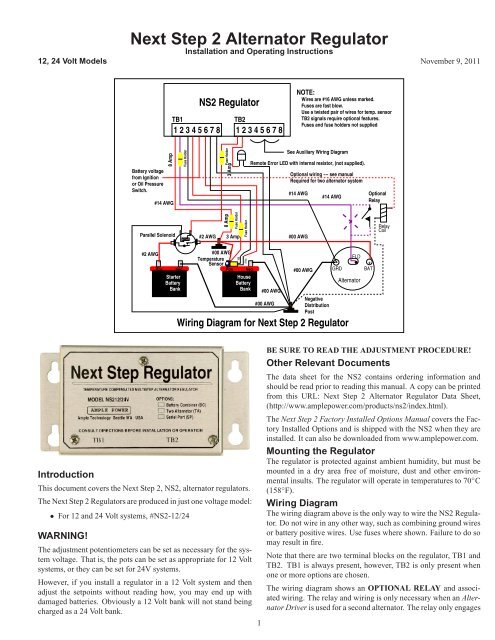
Wiring Diagram for <strong>Next</strong> <strong>Step</strong> 2 <strong>Regulator</strong><br />
1<br />
FLD<br />
<strong>Alternator</strong><br />
Optional<br />
Relay<br />
+<br />
BAT<br />
Relay<br />
Coil<br />
BE SURE TO READ THE ADJUSTMENT PROCEDURE!<br />
Other Relevant Documents<br />
The data sheet for the NS2 contains ordering information and<br />
should be read prior to reading this manual. A copy can be printed<br />
from this URL: <strong>Next</strong> <strong>Step</strong> 2 <strong>Alternator</strong> <strong>Regulator</strong> Data Sheet,<br />
(http://www.amplepower.com/products/ns2/index.html).<br />
The <strong>Next</strong> <strong>Step</strong> 2 Factory Installed Options Manual covers the Factory<br />
Installed Options and is shipped with the NS2 when they are<br />
installed. It can also be downloaded from www.amplepower.com.<br />
Mounting the <strong>Regulator</strong><br />
The regulator is protected against ambient humidity, but must be<br />
mounted in a dry area free of moisture, dust and other environmental<br />
insults. The regulator will operate in temperatures to 70 ◦ C<br />
(158 ◦ F).<br />
Wiring Diagram<br />
The wiring diagram above is the only way to wire the NS2 <strong>Regulator</strong>.<br />
Do not wire in any other way, such as combining ground wires<br />
or battery positive wires. Use fuses where shown. Failure to do so<br />
may result in fire.<br />
Note that there are two terminal blocks on the regulator, TB1 and<br />
TB2. TB1 is always present, however, TB2 is only present when<br />
one or more options are chosen.<br />
The wiring diagram shows an OPTIONAL RELAY and associated<br />
wiring. The relay and wiring is only necessary when an <strong>Alternator</strong><br />
Driver is used for a second alternator. The relay only engages
if the main ignition is on, preventing field current from flowing in<br />
the main alternator if the engine is not being operated. Optional<br />
wiring is shown with dashed lines. Note the large dashed X through<br />
the field wire. It denotes that the field wire is interrupted at the X<br />
and re–wired through the relay.<br />
TB1 Signal Names and Functions<br />
• Pin 1, B + , (required) . . . The source of power for the alternator<br />
field current and regulator logic circuits which stay activated<br />
to provide the battery combiner function on the parallel<br />
solenoid output. Amperage draw on this wire is rated at 8<br />
Amps(12V) or 5 Amps(24V) maximum, enough for a single<br />
alternator.<br />
• Pin 2, FIELD, (required) . . . the wire driven positive to activate<br />
the alternator.<br />
• Pin 3, ALT GND, (required) . . . the return line for the field current.<br />
Amperage draw on this wire is rated at 8 Amps maximum.<br />
• Pin 4, BAT.VOLTS, (required) . . . the sense wire for battery<br />
voltage. Any erroneous voltage drop in this wire from the<br />
battery can cause overcharge.<br />
• Pin 5, ON/OFF, (required) . . . a positive voltage that turns on<br />
the field output regulator. Typically it is connected to the<br />
ignition switch or oil pressure switch. NOTE: On gasoline<br />
engines DO NOT connect at the spark coil . . . connect at<br />
the ignition switch.<br />
• Pin 6, T+ (RED), (optional) . . . positive side of the temperature<br />
sensor. Voltage at T+ (RED) is 2.98V at @ 25 ◦ C (77 ◦ F), and<br />
varies plus and minus with temperature at the rate of 0.01V<br />
per degree C.<br />
• Pin 7, T- (BLK), (optional) . . . ground side of the temperature<br />
sensor which is supplied with the regulator.<br />
• Pin 8 GROUND, (required – connect this wire first) . . . the<br />
reference ground for the regulator. All battery voltages are<br />
referenced to this wire.<br />
TB2 Signal Names and Functions, Optional<br />
• Pin 1, PARALLEL, (optional) . . . a positive output signal that<br />
is asserted after 30 seconds and when the regulator detects<br />
that the house battery is being charged.. Maximum load is<br />
0.5 Amps. This signal is active at all times to implement the<br />
Battery Combiner function. The output signal matches system<br />
voltage so always use a solenoid rated for battery voltage<br />
. . . for instance, 24 for a 24V battery bank.<br />
• Pin 2, Error, (optional) . . . a positive output signal that provides<br />
troubleshooting information identical to the Red Error<br />
LED . . . see the Error Indicator section. Maximum current permitted<br />
from this output is 0.5 Amps.<br />
• Pin 3, ON/OFF, Engine 2, (optional ) . . . a positive input voltage<br />
that turns on the optional <strong>Alternator</strong> Driver output for<br />
the second alternator. Typically it is connected to the ignition<br />
switch or oil pressure switch of the second engine.<br />
• Pin 4, Reg–Drv–2–Y, (optional ) . . . drive signal Y to the <strong>Alternator</strong><br />
Driver.<br />
• Pin 5, Reg–Drv–2–Z, (optional ) . . . drive signal Z to the <strong>Alternator</strong><br />
Driver.<br />
• Pin 6 GROUND, (optional) . . . ground for the serial port.<br />
• Pin 7, RX, (optional ) . . . serial port receive input<br />
• Pin 8,TX, (optional ) . . . serial port transmit<br />
2<br />
Voltage Setpoints<br />
Suggested battery voltage set-points are specified for 12, and 24<br />
Volt systems. One model covers both 12 and 24 Volts. Only the<br />
12/24 Volt values are given in this manual.<br />
The suggested setpoint values are not specific to any battery type.<br />
Consult your battery manufacturer to determine the optimum setpoints<br />
for their batteries. Adjust absorption time so that the batteries<br />
are fully charged just prior to when the regulator trips to float.<br />
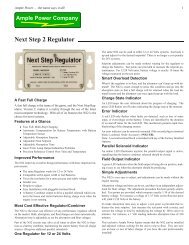
Parts Locations<br />
Setpoint 12V 24V<br />
Absorption 14.40 28.80<br />
Float 13.60 26.20<br />
The outline above shows the location of parts relevant to adjusting<br />
the NS2 setpoints and also shows the location of the LED indicators.<br />
The testpoints hold a typical multimeter probe. There is a<br />
ground testpoint for the black lead, and three testpoints for the red<br />
lead. Test points are adjacent to the potentiometer used to vary the<br />
voltage at the test point.<br />
Status Indicator<br />
The green LED shows at which set-point the regulator is presently<br />
operating. Status is shown by flashing the green LED with On and<br />
Off time in seconds as shown below.<br />
Table 1. Green Status LED<br />
Status On Off<br />
On/Off Inputs, Off 3 3<br />
Bulk Charge 2 1<br />
Absorption Charge 1 1<br />
<strong>Step</strong> to Float 1 6<br />
Float Charge 2 2<br />
Equalization Charge 6 6<br />
Error Indicator<br />
Abnormal conditions are reported with the Red LED, and the external<br />
lamp/alarm, if wired. Errors are identified by On and Off<br />
times of the Red LED as shown below.<br />
Table 2. Red Error LED
Error On Off<br />
Bat. Volts disconnected 3 1<br />
Over/Under Temperature 3 3<br />
Voltage Runaway 6 3<br />
Bad Temperature Sensor 6 6<br />
Float setpoint higher than absorption Continuous n/a<br />
Parallel Indicator<br />
The parallel indicator illuminates when the parallel output is activated.<br />
A connected solenoid should be closed anytime the parallel<br />
LED is on. The Battery Combiner option is required.<br />
Field Indicator<br />
The field indicator is active whenever the field drive is active. The<br />
field output goes on and off to control alternator output. The field<br />
LED does change brightness somewhat depending on how high alternator<br />
current is.<br />
Voltage Setpoint Adjustments<br />
Adjustments are easily made using a voltmeter. The regulator<br />
doesn’t need to be regulating while adjustments are made so leave<br />
the engine off.<br />
Begin adjustment by setting the meter to read voltage at a scale<br />
which will accommodate 3.3 Volts. Put the negative meter lead in<br />
the ground test point . . . see the figure above.<br />
Put the positive meter lead in a selected test point for absorption or<br />
float voltage. For the 12/24 Volt model, adjust the associated potentiometer<br />
until the voltmeter reads exactly one–tenth of the desired<br />
battery voltage . . . for instance 1.440 for a desired absorption<br />
voltage of 14.40 Volts.<br />
Repeat for the other voltage setpoint. The potentiometers are 20<br />
turns and have a clutch to prevent damage if turned beyond the<br />
limit.<br />
Adjusting the regulator while observing battery voltage is risky<br />
and can only be done accurately with the temperature sensor dis–<br />
connected. Normally, adjustments should be made as described<br />
above.<br />
DO NOT MEASURE BATTERY VOLTAGE WITH THE EN-<br />
GINE RUNNING AND ADJUST THE POT EXPECTING AN<br />
INSTANTANEOUS CHANGE IN BATTERY VOLTAGE. AL-<br />
WAYS MEASURE THE TESTPOINT VOLTAGE TO MAKE<br />
SURE THE POT IS SET APPROPRIATELY. FAILURE TO<br />
OBSERVE THIS WARNING MAY CAUSE YOUR BATTER-<br />
IES TO BE OVERCHARGED AND POSSIBLY EXPLODE.<br />
Absorption Time Adjustment<br />
How long the regulator stays in absorption state is set by measuring<br />
the voltage on the Absorption Time testpoint. Voltage is translated<br />
to minutes of absorption time by multiplying the voltage by 100.<br />
That is, a reading of 1 Volt will provide an absorption time of 100<br />
minutes.<br />
What You Should See<br />
When the regulator is first connected to B+, the red LED will glow<br />
for approximately 5 seconds before extinguishing. The alternator<br />
should slowly start to charge after the red LED goes off. Then the<br />
green LED will start to flash status information. For example: 2<br />
seconds on, 1 second off, (bulk charge). The green LED connected<br />
to the field output will illuminate and vary somewhat in intensity<br />
depending on the average field voltage level.<br />
3<br />
The regulator will not stay in bulk charge mode long if the batteries<br />
are full, or the alternator can produce more than the batteries will<br />
accept.<br />
The regulator cannot drive the battery voltage to any specific level<br />
if the alternator is not capable of producing enough current to<br />
satisfy battery acceptance capability, which varies with state–of–<br />
charge.<br />
<strong>Alternator</strong>s don’t produce maximum output unless they are rotating<br />
at 6000 to 7000 RPM, so don’t expect high current unless the alternator<br />
is rotating fast. If the batteries won’t accept high current, then<br />
the voltage will quickly rise to the absorption setpoint and hold at<br />
that voltage. The regulator hasn’t skipped the bulk charge step, just<br />
moved through it rapidly because the batteries don’t accept much<br />
current.<br />
Its very unlikely that a regulator is to blame for slow charging.<br />
They either work or they don’t. Failure to charge is generally the<br />
alternator, or electrical connections.<br />
Battery Temperature Sensing<br />
For optimal battery life we recommend using the battery temperature<br />
sensor. The temperature sensor accessory is an external temperature<br />
probe that attaches to the battery. The NS2 will then compensate<br />
the charging voltages based on the temperature to provide<br />
the fastest charge while protecting the life of the battery. Order<br />
Accessory: Battery temperature sensor, #2018<br />
or<br />
Battery temperature sensor with 20 feet (6-m) twisted pair wire,<br />
#2018-WIRE<br />
<strong>Alternator</strong> Requirements<br />
The alternator must be an externally regulated model with one<br />
brush connected to ground and the other brush fitted with a connection<br />
to make the field connection, (P-type). Be advised that<br />
alternators not hot rated for continuous operation at high current<br />
and temperature may fail when driven by the regulator.<br />
An alternator can easily be tested by disconnecting the field wire<br />
from the regulator and then with another wire, connecting the alternator<br />
field terminal to battery voltage. Don’t do this very long<br />
because the alternator will be producing maximum output for its<br />
RPM, and battery voltage may rise to unacceptable values.<br />
Troubleshooting<br />
First, look at the Signal Names and Functions section above and make<br />
sure that all required wires are in place and properly connected.<br />
Moving a wire such as BAT.VOLTS or GROUND a few feet away<br />
from a good Battery Positive or Negative Distribution could result<br />
in undesirable regulation due to voltage spikes in the system. To<br />
help diagnose voltage set-points, remove the T+ (RED) connection<br />
to prevent a faulty temperature sensor from affecting the system.<br />
Second, if the problem still exists, obtain a copy of the <strong>Next</strong> <strong>Step</strong><br />
2 Troubleshooting Guide which is available from the following<br />
sources:<br />
<strong>Regulator</strong> Service Center<br />
• the dealer who sold the regulator<br />
• Web: http://www.amplepower.com/support/<br />
• E-mail: support@amplepower.com<br />
• Phone: (206) 789-0827 or Fax: (206) 789-9003<br />
The troubleshooting guide was designed to help isolate a majority<br />
of the installation problems. Fill out the Troubleshooting Guide to<br />
determine if all measurements meet the specified requirements.
Finally, if you are unable to remedy the problem, contact the regulator<br />
service center with the <strong>Next</strong> <strong>Step</strong> 2 Troubleshooting Guide<br />
completed for referencing.<br />
Factory Installed Options<br />
The basic NS2 can be enhanced with several options which are:<br />
• Two <strong>Alternator</strong> Option<br />
• Battery Combiner Option<br />
• Serial Port/Equalization Option<br />
Refer to the <strong>Next</strong> <strong>Step</strong> 2 <strong>Alternator</strong> <strong>Regulator</strong> data sheet for ordering<br />
information of the factory installed options, factory installed<br />
options with accessories, and accessories.<br />
Refer to the <strong>Next</strong> <strong>Step</strong> 2 Factory Installed Options Manual for additional<br />
information, including wiring instructions for these options.<br />
Note: The extra circuitry for the factory installed options are built<br />
into the NS2 only at the factory.<br />
The factory installed options are summarized below.<br />
Two <strong>Alternator</strong> Option<br />
The NS2, without the Two <strong>Alternator</strong> Option, can only be used<br />
with a single alternator. The NS2 can be ordered with the capability<br />
to regulate two alternators on the same or different engines. One<br />
alternator is regulated from the NS2 itself. The second alternator<br />
is regulated via an <strong>Alternator</strong> Driver module which connects to the<br />
NS2. The connection between the <strong>Alternator</strong> Driver and NS2 is<br />
made using high speed commnuncations over two wires. See pins<br />
4 and 5 on TB2.<br />
The NS2 uses low power signals to drive a second alternator via the<br />
<strong>Alternator</strong> Driver. In this case, the NS2 is mounted close to one al-<br />
ternator while the second alternator, with the <strong>Alternator</strong> Driver can<br />
be mounted up to fifty feet, (15 meters) away. Signals between the<br />
NS2 and <strong>Alternator</strong> Driver are low level, rather than power signals.<br />
This is a much more reliable method of driving two alternators than<br />
direct coupling of field current which can result in electrical noise<br />
and high voltage transients caused from ringing on long wires.<br />
Battery Combiner Option<br />
The Battery Combiner option includes circuits on the NS2 regulator<br />
and includes an external parallel solenoid to combine the Starter<br />
Battery Bank to the House Battery Bank when the NS2 detects the<br />
House Battery Bank is being charged.<br />
Serial Port/Equalization Option<br />
With the serial port option a user can communicate with the NS2<br />
using a personal computer. Communications with the NS2 requires<br />
a terminal emulator program such as HyperTerminal, and a user<br />
must understand a small subset of the Remote Access Protocol,<br />
RAP. A document covering the full RAP description can be downloaded<br />
from the <strong>Ample</strong> <strong>Power</strong> Website.<br />
Use of the serial port enhances operation of the NS2 by allowing:<br />
• view battery voltage and temperature;<br />
• change charge setpoints from the computer;<br />
• enable current limit and set its value;<br />
• equalize batteries;<br />
<strong>Ample</strong> <strong>Power</strong> products are manufactured by <strong>Ample</strong> <strong>Power</strong> Company, 2442 NW Market St., #43, Seattle, WA 98107 – USA<br />
Visit http://www.amplepower.com<br />
4<br />
A cable is supplied with the #NS2SP-CABLE and has the appropriate<br />
DB-9 connector for hook–up to a computer. Not all computers<br />
have serial ports so a USB–to–serial adapter may be required.<br />
AMPLE POWER