FULL 3D MODELING OF A RADIO-FREQUENCY QUADRUPOLE*
FULL 3D MODELING OF A RADIO-FREQUENCY QUADRUPOLE*
FULL 3D MODELING OF A RADIO-FREQUENCY QUADRUPOLE*
- TAGS
- modeling
- www.phy.anl.gov

Create successful ePaper yourself
Turn your PDF publications into a flip-book with our unique Google optimized e-Paper software.
<strong>FULL</strong> <strong>3D</strong> <strong>MODELING</strong> <strong>OF</strong> A <strong>RADIO</strong>-<strong>FREQUENCY</strong> <strong>QUADRUPOLE*</strong><br />
B. Mustapha # , A. A. Kolomiets and P. N. Ostroumov, ANL, Argonne, IL 60439, U.S.A.<br />
Abstract<br />
An integral part of the ongoing ATLAS efficiency and<br />
intensity upgrade is an RFQ to replace the first section of<br />
the existing injector. The proposed RFQ is 3.8 m long<br />
consisting of 106 cells with 30 keV/u input energy and<br />
260 keV/u output energy. The RFQ was designed using<br />
the DesRFQ code which produces a file consisting of the<br />
length, modulation and the 8 coefficients of the 8-term<br />
potential for every cell. To independently check the<br />
design we created full <strong>3D</strong> models of the RFQ including<br />
vane modulation in both Micro-Wave Studio (MWS) and<br />
Electro-Magnetic Studio (EMS). The MWS model was<br />
used for electrodynamics simulations and the EMS model<br />
was used to extract the electric fields cell by cell for beam<br />
dynamics simulations assuming the electrostatic<br />
approximation. A very good agreement was obtained<br />
between the full <strong>3D</strong> model and the 8-term potential<br />
description in TRACK. In addition to the standard<br />
sinusoidal vane profile we studied the option of<br />
converting the cells with maximum modulation (~ 40<br />
cells) into trapezoidal cell type. The output energy was<br />
increased from 260 keV/u to ~ 300 keV/u with minimal<br />
change in beam dynamics. This option is the final RFQ<br />
design.<br />
ATLAS UPGRADE AND RFQ DESIGN<br />
The efficiency and intensity upgrade of ATLAS was<br />
recently approved by DOE. The upgrade will increase the<br />
intensity of stable beams by a factor of 10 to make<br />
ATLAS the most intense low-energy stable ion beam<br />
source in the world. It will also double the efficiency for<br />
the transport and acceleration of exotic beams produced<br />
by the recently commissioned Californium Radioactive<br />
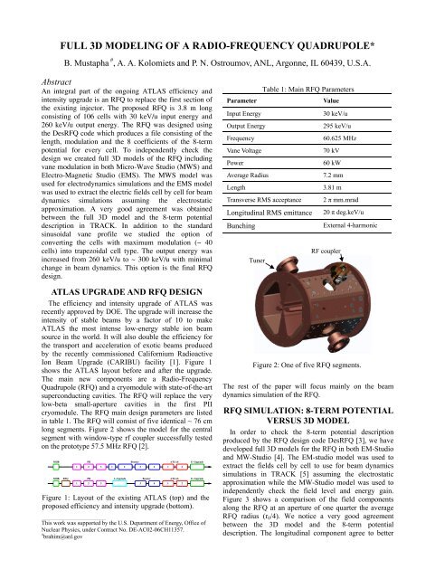
Ion Beam Upgrade (CARIBU) facility [1]. Figure 1<br />
shows the ATLAS layout before and after the upgrade.<br />
The main new components are a Radio-Frequency<br />
Quadrupole (RFQ) and a cryomodule with state-of-the-art<br />
superconducting cavities. The RFQ will replace the very<br />
low-beta small-aperture cavities in the first PII<br />
cryomodule. The RFQ main design parameters are listed<br />
in table 1. The RFQ will consist of five identical ~ 76 cm<br />
long segments. Figure 2 shows the model for the central<br />
segment with window-type rf coupler successfully tested<br />
on the prototype 57.5 MHz RFQ [2].<br />
MHB<br />
MHB<br />
RFQ<br />
1<br />
PII<br />
2 3<br />
1<br />
Booster<br />
1 2 3 4<br />
PII<br />
I−Upgrade<br />
Booster<br />
2 3 3 4<br />
ATLAS<br />
1 2<br />
ATLAS<br />
1 2<br />
E−Upgrade<br />
E−Upgrade<br />
Figure 1: Layout of the existing ATLAS (top) and the<br />
proposed efficiency and intensity upgrade (bottom).<br />
___________________________________________<br />
This work was supported by the U.S. Department of Energy, Office of<br />
Nuclear Physics, under Contract No. DE-AC02-06CH11357.<br />
# brahim@anl.gov<br />
Table 1: Main RFQ Parameters<br />
Parameter Value<br />
Input Energy 30 keV/u<br />
Output Energy 295 keV/u<br />
Frequency 60.625 MHz<br />
Vane Voltage 70 kV<br />
Power 60 kW<br />
Average Radius 7.2 mm<br />
Length 3.81 m<br />
Transverse RMS acceptance 2 π mm.mrad<br />
Longitudinal RMS emittance<br />
Bunching<br />
Tuner<br />
20 π deg.keV/u<br />
External 4-harmonic<br />
RF coupler<br />
Figure 2: One of five RFQ segments.<br />
The rest of the paper will focus mainly on the beam<br />
dynamics simulation of the RFQ.<br />
RFQ SIMULATION: 8-TERM POTENTIAL<br />
VERSUS <strong>3D</strong> MODEL<br />
In order to check the 8-term potential description<br />
produced by the RFQ design code DesRFQ [3], we have<br />
developed full <strong>3D</strong> models for the RFQ in both EM-Studio<br />
and MW-Studio [4]. The EM-studio model was used to<br />
extract the fields cell by cell to use for beam dynamics<br />
simulations in TRACK [5] assuming the electrostatic<br />
approximation while the MW-Studio model was used to<br />
independently check the field level and energy gain.<br />
Figure 3 shows a comparison of the field components<br />
along the RFQ at an aperture of one quarter the average<br />
RFQ radius (r0/4). We notice a very good agreement<br />
between the <strong>3D</strong> model and the 8-term potential<br />
description. The longitudinal component agree to better
than 1 % while the transverse components agree to 1-2 %.<br />
Figure 4 shows a comparison between the two models for<br />
the synchronous particle energy and phase. We notice a<br />
maximum phase deviation of ~ 2 degrees which is a<br />
tolerable error corresponding to a maximum energy<br />
deviation of ~ 0.4 keV/u. These differences may due to<br />
the precision of the 8-term potential coefficients from<br />
DesRFQ. Figure 5 shows the dependence of the RFQ<br />
output energy on the field level factor applied to the MW-<br />
Studio field distribution calculated for a total energy of 1<br />
Joule. In this case MW-Studio simulation results are used<br />
directly for particle tracking using Particle Studio to<br />
independently check the voltage and energy gain. From<br />
the figure we determine a threshold field level of ~ 1.18.<br />
The design field level is ~ 1.34 which corresponds to the<br />
design voltage of 70 kV in MW-Studio.<br />
Ex (V/cm)<br />
-25000<br />
Φsyn (deg) Wsyn (keV/u)<br />
Ez (V/cm)<br />
Ey (V/cm)<br />
-22000<br />
-23000<br />
-24000<br />
25000<br />
24000<br />
23000<br />
22000<br />
20000<br />
10000<br />
Figure 3: Comparison of the field components along the<br />
RFQ at r0/4. In red is the 8-term potential description and<br />
in green is the <strong>3D</strong> EM-Studio model.<br />
250<br />
225<br />
200<br />
175<br />
150<br />
125<br />
100<br />
75<br />
50<br />
25<br />
-30<br />
-35<br />
-40<br />
-45<br />
-50<br />
0<br />
-10000<br />
-20000<br />
50 100 150 200 250 300 350<br />
Z (cm)<br />
50 100 150 200 250 300 350<br />
Z (cm)<br />
50 100 150 200 250 300 350<br />
Z (cm)<br />
50 100 150 200 250 300 350<br />
Z (cm)<br />
50 100 150 200 250 300 350<br />
Z (cm)<br />
Figure 4: Comparison of the synchronous particle energy<br />
(top) and phase (bottom). In red is the 8-term potential<br />
description and in green is the <strong>3D</strong> model.<br />
Output energy (keV/u)<br />
300<br />
250<br />
200<br />
150<br />
100<br />
50<br />
0<br />
0.9 1 1.1 1.2 1.3 1.4<br />
Ez component (arb. units)<br />
Figure 5: Output beam energy as function of the field<br />
level factor in MW-Studio.<br />
RFQ DESIGN OPTIONS: SINUSOIDAL VS.<br />
TRAPEZOIDAL VANE MODULATION<br />
Following the leading work of the IHEP-Protvino<br />
group [6], we have investigated an alternate design option<br />
where the last cells with maximum modulation are<br />
converted to a trapezoidal vane profile. Figure 6 shows<br />
the geometry for both the sinusoidal and trapezoidal vane<br />
profiles. The longitudinal field calculated in EM-Studio<br />
for both geometries is shown on figure 7. We clearly<br />
notice that the field profile is narrower and more peaked<br />
in the trapezoidal case which leads to a higher transit time<br />
factor and more efficient acceleration. Converting the last<br />
40 cells from sinusoidal to trapezoidal vane modulation,<br />
the RFQ output energy increased from 260 keV/u to 295<br />
keV/u with limited effect on the beam dynamics.<br />
Therefore our final RFQ design combines a sinusoidal<br />
vane profile in the bunching section with a trapezoidal<br />
vane profile in the acceleration section with constant<br />
modulation. Figure 8 shows the full <strong>3D</strong> RFQ model with<br />
modulation in MW-Studio.<br />
Figure 6: Geometry for one modulation period in EM-<br />
Studio for sinusoidal (left) and trapezoidal (right) vanes.
Ez (V/m)<br />
40<br />
20<br />
0<br />
-20<br />
-40<br />
0 1 2 3 4 5 6 7 8 9 10<br />
Z (cm)<br />
Figure 7: Comparison of the longitudinal field profile<br />
between the sinusoidal (red) and trapezoidal (green) cells.<br />
Figure 8: Full <strong>3D</strong> model of the RFQ in MW-Studio.<br />
NEW TYPE <strong>OF</strong> OUTPUT MATCHER<br />
An output matcher is often used to produce an axis<br />
symmetric beam at the end of the RFQ to match the beam<br />
to a subsequent solenoid-based focusing lattice. Instead of<br />
the more standard output matcher geometry obtained by<br />
mirroring the input radial matcher, we here propose a new<br />
type of output matcher. Figure 9 shows the geometry for<br />
the new matcher. It consists of a first straight section of<br />
length L0 at the average radius R0 followed by a curved<br />
section of length Lc and ended with a second straight<br />
section of length L1 at a radius R1. Only the average<br />
radius R0 and the total matcher length L0+Lc+L1 are<br />
defined because of the limited RFQ length. The rest of<br />
parameters L0, L1 and R1 are determined by fit to produce<br />
an axis symmetric beam at the RFQ exit. A total matcher<br />
length of 1.5 times the length of a regular cell was enough<br />
to produce a symmetric beam while a standard matcher<br />
should be at least 3 times the length of a regular cell to<br />
work. This new type of output matcher relaxes the<br />
constraint on the total RFQ length because it can be much<br />
shorter. Figure 10 shows the graphics for a beam<br />
dynamics simulation of the LEBT and RFQ using<br />
TRACK for Q/A = 1/7 beam. The transverse phase space<br />
plots show the axis symmetric beam at the output of the<br />
RFQ.<br />
Figure 9: Geometry of the new type of output matcher.<br />
Figure 10: Beam Dynamics in the LEBT and RFQ for a<br />
Q/A = 1/7 beam. Note the axis symmetric beam at the<br />
RFQ exit.<br />
SUMMARY<br />
We have designed a new RFQ for the ATLAS<br />
efficiency and intensity upgrade. The original design was<br />
produced using the RFQ design code DesRFQ. To verify<br />
the 8-term potential description, we have developed a full<br />
<strong>3D</strong> model for the RFQ. The <strong>3D</strong> model agrees reasonably<br />
well with the 8-term potential description. In addition to<br />
the standard sinusoidal vane, we have studied a design<br />
that includes trapezoidal type cells. This option produces<br />
higher energy with limited effect on the beam dynamics.<br />
The final RFQ design combines both sinusoidal and<br />
trapezoidal vane types.<br />
REFERENCES<br />
[1] The CAlifornium Rare Isotope Breeder Upgrade<br />
(CARIBU): http://www.phy.anl.gov/atlas/caribu.<br />
[2] “High Power Test of a 57 MHz CW RFQ”, P. N.<br />
Ostroumov et al, proceedings of Linac 2006,<br />
Koxville, Tennesse, page 767.<br />
[3] The RFQ design software DesRFQ, A. A. Kolomiets<br />
et al, ITEP/ ANL Technical Note 2005.<br />
[4] CST EM- and MW-Studio, CST, GmbH, Darmstadt,<br />
Germany: http://www.cst.de.<br />
[5] The beam dynamics code TRACK:<br />
http://www.phy.anl.gov/atlas/TRACK.<br />
[6] O. K. Belyaev et al, Proceedings of the 20 th Linac<br />
Conference, Monterey, California, page 259.