PAM-120A/340A/480A Public Address Amplifier
PAM-120A/340A/480A Public Address Amplifier
PAM-120A/340A/480A Public Address Amplifier
- TAGS
- public
- amplifier
- inter-m.com

You also want an ePaper? Increase the reach of your titles
YUMPU automatically turns print PDFs into web optimized ePapers that Google loves.
<strong>PAM</strong>-<strong>120A</strong>/<strong>340A</strong>/<strong>480A</strong> <strong>Public</strong> <strong>Address</strong> <strong>Amplifier</strong><br />
CHANNEL 1 CHANNEL 2 CHANNEL 3 CHANNEL 4 CHANNEL 5 CHANNEL 6 BASS TREBLE MASTER CHIME SPEAKER<br />
MIN MAX MIN MAX MIN MAX MIN MAX MIN MAX MIN MAX<br />
12dB 12dB 12dB 12dB MIN MAX<br />
SP 1 SP 2 SP 3 SP 4 SP 5 ALL<br />
ON<br />
OFF<br />
POWER<br />
2<br />
0<br />
2<br />
4<br />
6<br />
8<br />
11<br />
14<br />
19<br />
24<br />
PROT<br />
OC03
Contents<br />
Welcome<br />
Warning.........................................................................................................................................1<br />
Unpacking......................................................................................................................................2<br />
Installation<br />
Environment....................................................................................................................................2<br />
Important Safety Instructions.............................................................................................................2<br />
Features............................................................................................................................................3<br />
Accessories.....................................................................................................................................3<br />
Operation ........................................................................................................................................3<br />
Front Panel ......................................................................................................................................4<br />
Rear Panel<br />
<strong>PAM</strong>-<strong>120A</strong> .....................................................................................................................................6<br />
<strong>PAM</strong>-<strong>340A</strong>/<strong>480A</strong>...........................................................................................................................8<br />
Connecting Speakers ...................................................................................................................11<br />
Applications<br />
<strong>PAM</strong>-<strong>120A</strong> ...................................................................................................................................13<br />
<strong>PAM</strong>-<strong>340A</strong>/<strong>480A</strong>.........................................................................................................................14<br />
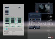
Block Diagram<br />
<strong>PAM</strong>-<strong>120A</strong> ...................................................................................................................................15<br />
<strong>PAM</strong>-<strong>340A</strong>/<strong>480A</strong>.........................................................................................................................16<br />
Specifications ................................................................................................................................17<br />
Service<br />
Procedures....................................................................................................................................18<br />
Schematic.....................................................................................................................................18<br />
Parts List .......................................................................................................................................18<br />
Variations and Options ...............................................................................................................18<br />
Warranty .......................................................................................................................................18
Welcome<br />
A personal welcome to you from the management and employees of Inter-M<br />
PUBLIC ADDRESS AMPLIFIER<br />
All of the co-workers here at Inter-M are dedicated to providing excellent products with inherently good value,<br />
and we are delighted you have purchased one of our products.<br />
We sincerely trust this product will provide years of satisfactory service, but if anything is not to your complete<br />
satisfaction, we will endeavor to make things right.<br />
Welcome to Inter-M, and thank you for becoming part of our worldwide extended family!<br />
CAUTION<br />
RISK OF ELECTRIC SHOCK<br />
DO NOT OPEN<br />
CAUTION: TO REDUCE THE RISK OF ELECTRIC SHOCK.<br />
DO NOT REMOVE COVER (OR BACK).<br />
NO USER-SERVICEABLE PARTS INSIDE.<br />
REFER SERVICING TO QUALIFIED SERVICE PERSONNEL.<br />
WARNING<br />
To prevent fire or shock hazard, do not<br />
expose the unit to rain or moisture.<br />
This symbol is intended to alert the user to the<br />
presence of uninsulated “dangerous voltage” within<br />
the product’s enclosure that may be of sufficient<br />
magnitude to constitute a risk of electric shock to<br />
persons.<br />
This symbol is intended to alert the user to the<br />
presence of important operation and maintenance<br />
(servicing) instructions in the literature accompanying<br />
the appliance.<br />
Caution: To prevent electric shock do not use this (polarized) plug with<br />
an extension cord, receptacle or other outlet unless the blades<br />
can be fully inserted to prevent blade exposure.<br />
Attentions: Pour prévenir les chocs électriques ne pas utiliser cette<br />
fiche polarisée avec un prolongateur, une prise de courant<br />
on une autre sortie de courant, sauf si les lames peuvent<br />
étre insérées à fond sans en laisser aucune partie à<br />
découvert.<br />
*Do not install this equipment in a confined space such as a book case or similar unit.<br />
*The apparatus shall not be exposed to dripping or splashing and no objects filled with liquids, such vases, shall be placed on the apparatus.<br />
*Worded: “WARNING FOR YOUR PROTECTION PLEASE READ THE FOLLOWING-WATER AND MOISTURE: Unit should not be used<br />
near water(e.g. near a bathtub, washbowl, kitchen sink, laundry tub, in a wet basement, or near a swimming pool, etc). Care should be taken<br />
so than objects do not fall and liquids are not spilled into the enclosure through openings.”<br />
<strong>PAM</strong>-<strong>120A</strong>/<strong>340A</strong>/<strong>480A</strong><br />
1
PUBLIC ADDRESS AMPLIFIER<br />
Unpacking<br />
Although your <strong>PAM</strong>-<strong>120A</strong> or <strong>PAM</strong>-<strong>340A</strong> or <strong>PAM</strong>-<strong>480A</strong> is neither complicated nor difficult to operate, we<br />
recommend you take a few minutes to read this brief manual and familiarize yourself with the important<br />
information regarding product features, setup and operation.<br />
As with most electronic devices, we strongly recommend you retain the original packaging. In the unlikely event<br />
the product must be returned for servicing, the original packaging (or reasonable equivalent) is required.<br />
Installation<br />
Environment<br />
Never place this product in an environment which could alter its performance or reduce its service life. Such<br />
environments usually include high levels of heat, dust, moisture, and vibration.<br />
Important Safety Instructions<br />
1. Read these instructions.<br />
2. Keep these instructions.<br />
3. Heed all warnings.<br />
4. Follow all instructions.<br />
5. Do not use this apparatus near water.<br />
6. Clean only with dry cloth.<br />
7. Do not block any ventilation openings. Install in accordance with the manufacturer’s instructions.<br />
8. Do not install near any heat sources such as radiators, heat registers, stoves, or other apparatus (including<br />
amplifiers) that produce heat.<br />
9. Do not defeat the safety purpose of the polarized or grounding-type plug. A polarized plug has two blades<br />
with one wider than the other. A grounding type plug has two blades and a third grounding prong. The wide<br />
blade or the third prong are provided for your safety. If the provided plug does not fit into your outlet, consult<br />
an electrician for replacement of the obsolete outlet.<br />
10. Protect the power cord from being walked on or pinched particularly at plugs, convenience receptacles, and<br />
the point where they exit from the apparatus.<br />
11. Only use attachments/accessories specified by the manufacturer.<br />
12. Use only with the cart, stand, tripod, bracket, or table specified by the manufacturer, or sold with the apparatus.<br />
When a cart is used, use caution when moving the cart/apparatus combination to avoid injury from tip-over.<br />
13. Unplug this apparatus during lightning storms or when unused for long periods of time.<br />
14. Refer all servicing to qualified service personnel. Servicing is required when the<br />
apparatus has been damaged in any way, such as power-supply cord or plug is<br />
damaged, liquid has been spilled or objects have fallen into the apparatus, the<br />
apparatus has been exposed to rain or moisture, does not operate normally, or has<br />
been dropped.<br />
2 <strong>PAM</strong>-<strong>120A</strong>/<strong>340A</strong>/<strong>480A</strong><br />
S3125A
Features<br />
PUBLIC ADDRESS AMPLIFIER<br />
- MODULAR DESIGN<br />
Optional modules can be installed in multiple configurations for convenience and ease of use. Choose the<br />
<strong>PAM</strong>-CDA (Compact Disc), <strong>PAM</strong>-T (AM/FM Tuner) or <strong>PAM</strong>-D (Cassette Deck) modules to expand the<br />
<strong>PAM</strong>-<strong>120A</strong>/<strong>340A</strong>/<strong>480A</strong>’s audio capabilities.<br />
- INDIVIDUAL INPUT GAIN CONTROLS<br />
Rear-panel gain controls for each input channel for total control of individual levels.<br />
- SPEAKER SELECT<br />
Six speaker select switches enable you to select any combination of up to five speakers.<br />
- SELECTABLE PRIORITY MUTING<br />
Switchable audio signal priority for Channels 1 and 2, Chime and Telephone input over other input sources.<br />
- REMOTE CONTROL INPUT (only <strong>PAM</strong>-<strong>340A</strong>/<strong>480A</strong>)<br />
Individual speaker zones can be selected and chime can be operated by wired remote control.<br />
- ANNOUNCEMENT CHIME<br />
Convenient four-tone chime for use with announcements.<br />
- EM(EMERGENCY) - OPTIONAL EMERGENCY VOICE IC (only <strong>PAM</strong>-<strong>340A</strong>/<strong>480A</strong>)<br />
When EM switch is pressed in emergencies, EM broadcasting stored in VOICE IC is outputted.<br />
Operation<br />
Make certain that speakers and input sources are properly connected before switching on.<br />
Keep volume levels turned down before switching on.<br />
NOTE: The system’s operation is delayed by approximately three seconds after pressing the power switch. This is<br />
due to the built-in protection circuitry, designed to protect the speakers and other system components.<br />
<strong>PAM</strong>-<strong>120A</strong>/<strong>340A</strong>/<strong>480A</strong><br />
3
PUBLIC ADDRESS AMPLIFIER<br />
Front Panel<br />
1. TUNER MODULE BAY<br />
This panel provides for installation of optional <strong>PAM</strong>-T (AM/FM Tuner) Module, via the unit’s internal<br />
connectors.<br />
2. CASSETTE DECK AND CD MODULE BAY<br />
This panel provides for installation of optional <strong>PAM</strong>-CDA (CD Player) or <strong>PAM</strong>-D (Cassette Deck) Modules, via<br />
the unit’s internal connectors.<br />
3. OUTPUT LEVEL DISPLAY<br />
This seven-segment LED meter indicates the amplifier’s output level in RMS.<br />
4. CHANNEL 1-6 VOLUME<br />
Controls the individual volume levels of Channels 1-6.<br />
5. TONE CONTROL<br />
Individual Bass and Treble controls are used to cut (decrease) or boost (increase) the lower and higher<br />
frequencies ±12dB.<br />
6. MASTER VOLUME<br />
This rotary switch controls the overall output volume of the amplifier’s output signal.<br />
7. CHIME BUTTON<br />
Pressing this switch activates the chime circuitry.<br />
4 <strong>PAM</strong>-<strong>120A</strong>/<strong>340A</strong>/<strong>480A</strong><br />
1<br />
CHANNEL 1 CHANNEL 2 CHANNEL 3 CHANNEL 4 CHANNEL 5 CHANNEL 6 BASS TREBLE MASTER CHIME SPEAKER<br />
MIN MAX MIN MAX MIN MAX MIN MAX MIN MAX MIN MAX<br />
12dB 12dB 12dB 12dB MIN MAX<br />
SP 1 SP 2 SP 3 SP 4 SP 5 ALL<br />
4 5 6 7 8 9 10<br />
2<br />
ON<br />
OFF<br />
3<br />
POWER<br />
2<br />
0<br />
2<br />
4<br />
6<br />
8<br />
11<br />
14<br />
19<br />
24<br />
PROT
8. SPEAKER SELECTOR SWITCHES<br />
These switches are used to select output to any combination of up to five individual speakers.<br />
PUBLIC ADDRESS AMPLIFIER<br />
9. POWER SWITCH<br />
Pressing this switch turns the unit on, as indicated by the Power LED above the switch. Pressing it again turns<br />
the unit off.<br />
10. PROTECTION INDICATOR<br />
This LED indicates the state of the amplifier’s protection circuitry. When the Protection LED is on (illuminated),<br />
the protection circuitry is active, indicating that the unit is not operating normally. This is typically due to<br />
overheating or power limiting. Please check the Input and Output condition of the amplifier.<br />
<strong>PAM</strong>-<strong>120A</strong>/<strong>340A</strong>/<strong>480A</strong><br />
5
PUBLIC ADDRESS AMPLIFIER<br />
Rear Panel (<strong>PAM</strong>-<strong>120A</strong>)<br />
SPEAKER SELECTOR<br />
4Ω SP 5 SP 4 SP 3 SP 2 SP 1<br />
1. SPEAKER OUTPUT TERMINAL STRIP<br />
Connect up to five individual speakers to this strip.<br />
Impedances for 4Ω, 70V and 100V operation are shown below. Connect speakers whose combined<br />
impedance is equal to or higher than the rated output impedance, as shown below.<br />
2. IMPEDANCE SELECTOR<br />
Selects between high impedance operation at 70V or 100V distributed systems. Note that when speakers are<br />
connected to the 4Ω terminal, this switch is inactive.<br />
3. ANTENNA CONNECTOR (OPTIONAL)<br />
This terminal is used to connect the antenna, when used with the optional <strong>PAM</strong>-T AM/FM Tuner module.<br />
4. EQ CONTROLS<br />
Three-band equalization control provides ±12dB of cut (decrease) or boost (increase) over the high, mid and<br />
low frequency ranges of the individual channel signals.<br />
HIGH – 10kHz, ±12dB MID – 1kHz, ±12dB LOW – 100Hz, ±12dB<br />
5. PHANTOM POWER SWITCH<br />
This switch turns the phantom power supply on or off for all channels. When the switch is turned on, +22V DC<br />
power is supplied to pins 2 and 3 of each channel’s input connector.<br />
Use phantom power when connecting condenser microphones, which require an external power supply.<br />
NOTE: It is safe to connect most modern dynamic microphones or line level devices to the channel inputs<br />
when phantom power is activated. However, some older ribbon microphones may be damaged by<br />
phantom power, and certain unbalanced line level devices may malfunction or produce an audible<br />
hum when phantom power is active.<br />
6 <strong>PAM</strong>-<strong>120A</strong>/<strong>340A</strong>/<strong>480A</strong><br />
COM<br />
~AC INPUT<br />
230V 50Hz, 135W<br />
EXT<br />
CHIME<br />
EXT<br />
MUTE<br />
CAUTION; TO REDUCE THE RISK OF ELECTRIC SHOCK,<br />
DO NOT REMOVE COVER. NO USER SERVICEABLE PARTS INSIDE.<br />
REFER SERVICING TO QUALIFIED SERVICE PERSONNEL.<br />
AVIS; RISQUE DE CHOC ELECTRIQUE NE PAS OUVRIR.<br />
S<br />
N<br />
MADE IN KOREA<br />
IMPEDANCE SELECTOR<br />
100V<br />
(83Ω)<br />
70V<br />
(42Ω)<br />
DC INPUT<br />
24V<br />
FM<br />
MODEL NO. <strong>PAM</strong>-<strong>120A</strong><br />
PUBLIC ADDRESS AMPLIFIER<br />
OUTPUT POWER: 120W<br />
COM AM<br />
LINK IN<br />
PREAMP OUT AMP IN<br />
www.inter-m.com<br />
MODEL 4Ω 70V 100V<br />
<strong>PAM</strong>-<strong>120A</strong> 22V 42Ω 83Ω
PUBLIC ADDRESS AMPLIFIER<br />
6. PRIORITY SWITCH<br />
When selected, these switches will give priority to Channels 1 and/or 2 over all other channels and audio<br />
inputs.<br />
7. AC POWER INPUT<br />
Connect a standard three-pin AC cable your AC outlet.<br />
8. EXT CHIME<br />
When these two terminals are shorted, the four-tone chime circuitry is activated.<br />
9. EXT MUTE<br />
When these two terminals are shorted by wired remote, signals from Input Channels 3-6 and any optional<br />
modules are muted. Signals from Channel 1, Channel 2, Link In and Chime are not muted.<br />
10. DC INPUT TERMINALS<br />
These terminals are provided for the connection of backup battery. Connect a 24VDC battery source to these<br />
terminals. Make certain the red terminal is connected to the battery’s positive (+) side, and the black terminal<br />
to the battery’s negative (–) side.<br />
11. PREAMP OUTPUT<br />
This output connects the unit with an external power amplifier. Inserting a plug into the Preamp Out jack will<br />
disconnect signal to the unit’s power amp, sending the output of the internal mixer to the external amplifier.<br />
12. AMP IN<br />
This input connects an external mixer or preamp with the unit’s power amp. Inserting a plug into the Amp In jack<br />
will disconnect all input signal from the unit’s internal mixer. Only signal from the external source will be heard.<br />
13. LINK IN<br />
This line-level input connects the unit with an external mixer for expanded input channels.<br />
14. CHANNEL INPUTS 1-6<br />
These balanced three-pin XLR connectors accept a standard microphone cable or other low impedance signal.<br />
Optional phone jack, screw terminal, RCA jack or transformer balanced inputs are also available.<br />
15. INPUT GAIN CONTROLS<br />
These knobs provide continuous control of the input levels for each of the six input channels. When adjusting<br />
the input gain, make certain that the levels are not set too high, or distortion will result.<br />
The approximate levels for these controls are as follows:<br />
MIC mic level (-50dB ~ -60dB)<br />
MIC ATT instrument level (-30dB ~ -50dB)<br />
AUX line level (-20dB ~ -30dB)<br />
<strong>PAM</strong>-12A/<strong>340A</strong>/<strong>480A</strong><br />
7
PUBLIC ADDRESS AMPLIFIER<br />
Rear Panel (<strong>PAM</strong>-<strong>340A</strong>/<strong>480A</strong>)<br />
EM EXT EXT<br />
CHIME MUTE<br />
1. SPEAKER OUTPUT TERMINAL STRIP<br />
Connect up to five individual speakers to this strip.<br />
Impedances for 100V operation are shown below. Connect speakers whose combined impedance is equal to<br />
or higher than the rated output impedance, as shown below.<br />
2. ANTENNA CONNECTOR (OPTIONAL)<br />
This terminal is used to connect the antenna, when used with the optional <strong>PAM</strong>-T AM/FM Tuner module.<br />
3. EQ CONTROLS<br />
Three-band equalization control provides ±12dB of cut (decrease) or boost (increase) over the high, mid and<br />
low frequency ranges of the individual channel signals.<br />
HIGH – 10kHz, ±12dB MID – 1kHz, ±12dB LOW – 100Hz, ±12dB<br />
4. PHANTOM POWER SWITCH<br />
This switch turns the phantom power supply on or off for all channels. When the switch is turned on, +22V<br />
DC power is supplied to pins 2 and 3 of each channel’s input connector.<br />
Use phantom power when connecting condenser microphones, which require an external power supply.<br />
NOTE: It is safe to connect most modern dynamic microphones or line level devices to the channel inputs<br />
when phantom power is activated. However, some older ribbon microphones may be damaged by<br />
phantom power, and certain unbalanced line level devices may malfunction or produce an audible<br />
hum when phantom power is active.<br />
8 <strong>PAM</strong>-<strong>120A</strong>/<strong>340A</strong>/<strong>480A</strong><br />
COM<br />
~AC INPUT<br />
230V 50Hz, 360W<br />
SPEAKER SELECTOR<br />
(IMPEDANCE: 20.8Ω)<br />
SP 5 SP 4 SP 3 SP 2 SP 1<br />
CAUTION; TO REDUCE THE RISK OF ELECTRIC SHOCK,<br />
DO NOT REMOVE COVER. NO USER SERVICEABLE PARTS INSIDE.<br />
REFER SERVICING TO QUALIFIED SERVICE PERSONNEL.<br />
AVIS; RISQUE DE CHOC ELECTRIQUE NE PAS OUVRIR.<br />
S<br />
N<br />
MADE IN KOREA<br />
FM<br />
MODEL NO. <strong>PAM</strong>-<strong>480A</strong><br />
PUBLIC ADDRESS AMPLIFIER<br />
OUTPUT POWER: 480W<br />
COM AM<br />
LINK IN<br />
REMOTE AMPLIFIER PREAMP OUT AMP IN<br />
www.inter-m.com<br />
PHANTOM<br />
HIGH<br />
MID<br />
LOW<br />
TRIM<br />
+12<br />
HIGH<br />
-12<br />
+12<br />
-12<br />
+12<br />
LOW<br />
-12<br />
-60<br />
-16<br />
CH 6<br />
PHANTOM<br />
MID<br />
TRIM<br />
CH 5<br />
+12<br />
-12<br />
+12<br />
LOW<br />
-12<br />
PHANTOM<br />
+12<br />
HIGH<br />
-12<br />
MID<br />
-60<br />
TRIM<br />
-16<br />
MODEL 100V<br />
<strong>PAM</strong>-<strong>340A</strong> 29.4Ω<br />
<strong>PAM</strong>-<strong>480A</strong> 20.8Ω<br />
+12<br />
HIGH<br />
-12<br />
CH 4<br />
+12<br />
-12<br />
+12<br />
LOW<br />
-12<br />
-60<br />
-16<br />
PHANTOM<br />
MID<br />
TRIM<br />
+12<br />
-12<br />
-60<br />
-16<br />
CH 3<br />
PRIORITY<br />
PHANTOM<br />
+12<br />
HIGH<br />
-12<br />
MID<br />
+12<br />
LOW<br />
-12<br />
TRIM<br />
CH 2<br />
+12<br />
-12<br />
+12<br />
LOW<br />
-12<br />
-60<br />
-16<br />
PRIORITY<br />
PHANTOM<br />
+12<br />
HIGH<br />
-12<br />
MID<br />
TRIM<br />
CH 1<br />
+12<br />
-12<br />
+12<br />
-12<br />
+12<br />
-12<br />
-60<br />
-16
PUBLIC ADDRESS AMPLIFIER<br />
5. PRIORITY SWITCH<br />
When selected, these switches will give priority to Channels 1 and/or 2 over all other channels and audio inputs.<br />
6. AC POWER INPUT<br />
Connect a standard three-pin AC cable to your AC outlet.<br />
7. EM<br />
When EM switch is connected and pressed in fire or other emergencies, EM broadcasting stored in VOICE IC<br />
is outputted.<br />
* Remove an input jack from AMP IN not to affect Emergency signal to be played or adjust the main audio<br />
signal to adequate level for emergency broadcasting.<br />
8. EXT CHIME<br />
When these two terminals are shorted by wired remote (see item 14 above), the four-tone chime circuitry is<br />
activated.<br />
9. EXT MUTE<br />
When these two terminals are shorted by wired remote (see item 14 above), signals from Input Channels 3-6<br />
and any optional modules are muted. Signals from Channel 1, Channel 2, Link In and Chime are not muted.<br />
10. REMOTE CONTROL INPUT<br />
By connecting a 15-pin D-SUB connector, it is possible to control speaker zone selection and activate the<br />
chime via wired remote. Connection terminals for the remote are shown below.<br />
Pin 1: Remote amplifier input signal hot(+) Pin 8: Remote control 5(Speaker 5)<br />
Pin 2: Remote amplifier input signal cold(–) Pin 9: Remote control ground<br />
Pin 3: Signal ground Pin 10: DC +24V<br />
Pin 4: Remote control 1(Speaker 1) Pin 11: Input Chime<br />
Pin 5: Remote control 2(Speaker 2) Pin 12: NC<br />
Pin 6: Remote control 3(Speaker 3) Pin 13: NC<br />
Pin 7: Remote control 4(Speaker 4) Pin 14, 15: NC<br />
NOTE: Remote controller is used to RM-01.<br />
11. PREAMP OUTPUT<br />
This output connects the unit with an external power amplifier. Inserting a plug into the Preamp Out jack will<br />
disconnect signal to the unit’s power amp, sending the output of the internal mixer to the external amplifier.<br />
12. AMP IN<br />
This input connects an external mixer or preamp with the unit’s power amp. Inserting a plug into the Amp In jack<br />
will disconnect all input signal from the unit’s internal mixer. Only signal from the external source will be heard.<br />
13. LINK IN<br />
This line-level input connects the unit with an external mixer for expanded input channels.<br />
<strong>PAM</strong>-<strong>120A</strong>/<strong>340A</strong>/<strong>480A</strong><br />
9
PUBLIC ADDRESS AMPLIFIER<br />
14. CHANNEL INPUTS 1-6<br />
These balanced three-pin XLR connectors accept a standard microphone cable or other low impedance<br />
signal. Optional transformer balanced inputs are also available.<br />
15. INPUT GAIN CONTROLS<br />
These knobs provide continuous control of the input levels for each of the six input channels. When adjusting<br />
the input gain, make certain that the levels are not set too high, or distortion will result.<br />
The approximate levels for these controls are as follows:<br />
MIC mic level (-50dB ~ -60dB)<br />
MIC ATT instrument level (-30dB ~ -50dB)<br />
AUX line level (-20dB ~ -30dB)<br />
10 <strong>PAM</strong>-<strong>120A</strong>/<strong>340A</strong>/<strong>480A</strong>
Connecting Speakers<br />
PUBLIC ADDRESS AMPLIFIER<br />
Before connecting speakers, disconnect the AC power cable. Note the proper connecting terminals as shown<br />
below. Make certain that the total impedance is not less than the rated impedance indicated.<br />
- CONNECTING 4Ω OR 8Ω SPEAKER SYSTEMS (only <strong>PAM</strong>-<strong>120A</strong>)<br />
When connecting conventional 4Ω or 8Ω speaker systems, connect the speaker’s positive (+) side to the<br />
terminal labeled 4. Connect the speaker’s negative (–) side to the terminal labeled COM. See illustration<br />
below:<br />
COM<br />
- CONNECTING HIGH-VOLTAGE DISTRIBUTED SPEAKER SYSTEMS<br />
SPEAKER OUTPUT<br />
SP 1 SP 2 SP 3 SP 4 SP 5<br />
When connecting a high-impedance speaker system in parallel, you can connect speakers with a total<br />
rated input of up to 120W (<strong>PAM</strong>-<strong>120A</strong>) or 340W (<strong>PAM</strong>-<strong>340A</strong>) or 480W(<strong>PAM</strong>-<strong>480A</strong>).<br />
10W 10W<br />
10W<br />
10W<br />
COM<br />
SPEAKER SELECTOR<br />
SP 5 SP 4 SP 3 SP 2 SP 1<br />
Total rated input of up to 120W (<strong>PAM</strong>-<strong>120A</strong>) or 340W (<strong>PAM</strong>-<strong>340A</strong>) or 480W(<strong>PAM</strong>-<strong>480A</strong>)<br />
<strong>PAM</strong>-<strong>120A</strong>/<strong>340A</strong>/<strong>480A</strong><br />
11
PUBLIC ADDRESS AMPLIFIER<br />
For example, if you are connecting speakers with a rated input of 15W, you can connect up to 8 speakers<br />
in parallel, as shown below:<br />
WARNING: Extreme care must be exercised when connecting low-impedance systems, as potentially hazardous<br />
voltages may be present at these terminals.<br />
Do not install this equipment in a confined space with less-than-adequate ventilation.<br />
12 <strong>PAM</strong>-<strong>120A</strong>/<strong>340A</strong>/<strong>480A</strong><br />
15W 15W<br />
15W<br />
15W<br />
15Wx8 units(120W(<strong>PAM</strong>-<strong>120A</strong>))<br />
COM<br />
SPEAKER SELECTOR<br />
SP 5 SP 4 SP 3 SP 2 SP 1
Applications (<strong>PAM</strong>-<strong>120A</strong>)<br />
COM<br />
SPEAKER SELECTOR<br />
4Ω SP 5 SP 4 SP 3 SP 2 SP 1<br />
~AC INPUT<br />
230V 50Hz, 135W<br />
EXT<br />
CHIME<br />
EXT<br />
MUTE<br />
CAUTION; TO REDUCE THE RISK OF ELECTRIC SHOCK,<br />
DO NOT REMOVE COVER. NO USER SERVICEABLE PARTS INSIDE.<br />
REFER SERVICING TO QUALIFIED SERVICE PERSONNEL.<br />
AVIS; RISQUE DE CHOC ELECTRIQUE NE PAS OUVRIR.<br />
S<br />
N<br />
MADE IN KOREA<br />
IMPEDANCE SELECTOR<br />
100V<br />
(83Ω)<br />
70V<br />
(42Ω)<br />
DC INPUT<br />
24V<br />
FM<br />
MODEL NO. <strong>PAM</strong>-<strong>120A</strong><br />
PUBLIC ADDRESS AMPLIFIER<br />
OUTPUT POWER: 120W<br />
COM AM<br />
LINK IN<br />
PREAMP OUT AMP IN<br />
www.inter-m.com<br />
OTHER SOURCE<br />
•<br />
•<br />
PUBLIC ADDRESS AMPLIFIER<br />
<strong>PAM</strong>-<strong>120A</strong>/<strong>340A</strong>/<strong>480A</strong><br />
13
PUBLIC ADDRESS AMPLIFIER<br />
Applications (<strong>PAM</strong>-<strong>340A</strong>/<strong>480A</strong>)<br />
EM EXT EXT<br />
CHIME MUTE<br />
CAUTION; TO REDUCE THE RISK OF ELECTRIC SHOCK,<br />
DO NOT REMOVE COVER. NO USER SERVICEABLE PARTS INSIDE.<br />
REFER SERVICING TO QUALIFIED SERVICE PERSONNEL.<br />
AVIS; RISQUE DE CHOC ELECTRIQUE NE PAS OUVRIR.<br />
S<br />
N<br />
MADE IN KOREA<br />
14 <strong>PAM</strong>-<strong>120A</strong>/<strong>340A</strong>/<strong>480A</strong><br />
COM<br />
~AC INPUT<br />
230V 50Hz, 360W<br />
SPEAKER SELECTOR<br />
(IMPEDANCE: 20.8Ω)<br />
SP 5 SP 4 SP 3 SP 2 SP 1<br />
FM<br />
MODEL NO. <strong>PAM</strong>-<strong>480A</strong><br />
PUBLIC ADDRESS AMPLIFIER<br />
OUTPUT POWER: 480W<br />
COM AM<br />
LINK IN<br />
REMOTE AMPLIFIER PREAMP OUT AMP IN<br />
www.inter-m.com<br />
RM-05A<br />
PHANTOM<br />
MID<br />
•<br />
OTHER SOURCE<br />
+12<br />
MID<br />
-12<br />
CH 6<br />
PHANTOM<br />
CH 5<br />
PHANTOM<br />
+12<br />
MID<br />
-12<br />
+12<br />
MID<br />
-12<br />
CH 4<br />
PHANTOM<br />
CH 3<br />
PRIORITY<br />
PHANTOM<br />
+12<br />
+12<br />
+12<br />
+12<br />
+12<br />
HIGH<br />
HIGH<br />
HIGH<br />
HIGH<br />
HIGH<br />
HIGH<br />
-12<br />
-12<br />
-12<br />
-12<br />
-12<br />
+12<br />
MID<br />
-12<br />
+12<br />
+12<br />
+12<br />
+12<br />
+12<br />
LOW<br />
LOW<br />
LOW<br />
LOW<br />
LOW<br />
LOW<br />
-12<br />
-12<br />
-12<br />
-12<br />
-12<br />
-60<br />
-60<br />
-60<br />
-60<br />
-60<br />
TRIM<br />
TRIM<br />
TRIM<br />
TRIM<br />
TRIM<br />
TRIM<br />
-16<br />
-16<br />
-16<br />
-16<br />
-16<br />
•<br />
CH 2<br />
PRIORITY<br />
PHANTOM<br />
+12<br />
MID<br />
-12<br />
CH 1<br />
+12<br />
-12<br />
+12<br />
-12<br />
+12<br />
-12<br />
-60<br />
-16
Block Diagram (<strong>PAM</strong>-<strong>120A</strong>)<br />
PUBLIC ADDRESS AMPLIFIER<br />
<strong>PAM</strong>-<strong>120A</strong>/<strong>340A</strong>/<strong>480A</strong><br />
15
PUBLIC ADDRESS AMPLIFIER<br />
Block Diagram (<strong>PAM</strong>-<strong>340A</strong>/<strong>480A</strong>)<br />
16 <strong>PAM</strong>-<strong>120A</strong>/<strong>340A</strong>/<strong>480A</strong>
Specifications<br />
PUBLIC ADDRESS AMPLIFIER<br />
Rated Output Power.................................................................................<strong>PAM</strong>-<strong>120A</strong>(THD 1%) : 120W (RMS)<br />
..........................................................................................................<strong>PAM</strong>-<strong>340A</strong>(THD 3%) : 340W (RMS)<br />
..........................................................................................................<strong>PAM</strong>-<strong>480A</strong>(THD 3%) : 480W (RMS)<br />
Frequency Response<br />
Amp In ....................................................................................................................................80Hz~20kHz<br />
Link In......................................................................................................................................80Hz~15kHz<br />
CH1~CH6................................................................................................................................120Hz~8kHz<br />
Remote In ...........................................................................................120Hz~8kHz(<strong>PAM</strong>-<strong>340A</strong>, <strong>PAM</strong>-<strong>480A</strong>)<br />
T.H.D.(at 1kHz Rated Output)...................................................................................Less than 1%(<strong>PAM</strong>-<strong>120A</strong>)<br />
T.H.D.(at 1kHz Half Power Output) .....................................................Less than 0.5%(<strong>PAM</strong>-<strong>340A</strong>, <strong>PAM</strong>-<strong>480A</strong>)<br />
S/N<br />
Amp In .............................................................................................................Better than 90dB(<strong>PAM</strong>-<strong>120A</strong>)<br />
.........................................................................................................Better than 88dB(<strong>PAM</strong>-<strong>340A</strong>/<strong>480A</strong>)<br />
Link In .................................................................................................................................Better than 65dB<br />
CH1~CH6 ...........................................................................................................................Better than 50dB<br />
Remote In ...............................................................................................Better than 50dB(<strong>PAM</strong>-<strong>340A</strong>/<strong>480A</strong>)<br />
Input Sensitivity/Impedance<br />
CH1~CH6<br />
TRIM VR -60dB Position ............................................................................................................1mV/10kΩ<br />
TRIM VR -16dB Position ........................................................................................................158mV/10kΩ<br />
Link In .................................................................................................................................100mV/10kΩ<br />
Amp In ....................................................................................................................1V/47kΩ(<strong>PAM</strong>-<strong>120A</strong>)<br />
....................................................................................................................1V/20kΩ(<strong>PAM</strong>-<strong>340A</strong>/<strong>480A</strong>)<br />
Remote In......................................................................................................1V/10KΩ(<strong>PAM</strong>-<strong>340A</strong>/<strong>480A</strong>)<br />
Speaker Output/Impedance...................................................<strong>PAM</strong>-<strong>120A</strong> : 120W/4Ω, 70V/42Ω, 100V/83Ω<br />
............................................................................................................<strong>PAM</strong>-<strong>340A</strong> : 340W, 100V/29.4Ω<br />
............................................................................................................<strong>PAM</strong>-<strong>480A</strong> : 480W, 100V/20.8Ω<br />
Preamp Output/Impedance ............................................................................................................1V/600Ω<br />
Tone Control (100Hz, 10kHz)..............................................................................................................±12dB<br />
CH1~CH6 EQ Control (100Hz, 1kHz, 10kHz) ......................................................................................±12dB<br />
- GENERAL<br />
Power Source.......................................100–120VAC or 220V–240VAC; 50/60Hz, 24V DC(only <strong>PAM</strong>-<strong>120A</strong>)<br />
..............................................................(Supplied AC mains transformer depends on country requirements)<br />
Power Consumption ..................<strong>PAM</strong>-<strong>120A</strong> : 135W(1/8 POWER), 200W(1/3 POWER), 300W(FULL POWER)<br />
...............................................<strong>PAM</strong>-<strong>340A</strong> : 260W(1/8 POWER), 400W(1/3 POWER), 620W(FULL POWER)<br />
...............................................<strong>PAM</strong>-<strong>480A</strong> : 360W(1/8 POWER), 550W(1/3 POWER), 880W(FULL POWER)<br />
Weight .................................................................................................................<strong>PAM</strong>-<strong>120A</strong> : 13kg/28.7lb<br />
.....................................................................................................................<strong>PAM</strong>-<strong>340A</strong> : 13.5kg/29.7lb<br />
.....................................................................................................................<strong>PAM</strong>-<strong>480A</strong> : 15.5kg/34.2lb<br />
Dimensions ........................................................420(W) x 132(H) x 360(D)mm/16.5(W) x 5.2(H) x 14.2(D)in<br />
Operation Temperature..........................................................................................14F~104F (-10°C~+40°C)<br />
* Specifications and design subject to change without notice.<br />
<strong>PAM</strong>-<strong>120A</strong>/<strong>340A</strong>/<strong>480A</strong><br />
17
PUBLIC ADDRESS AMPLIFIER<br />
Service<br />
Procedures<br />
Ensure the problem is not related to operator error, or system devices that are external to this unit. Information<br />
provided in the troubleshooting portion of this manual may help with this process. Once it is certain that the<br />
problem is related to the product contact your warranty provider as described in the warranty section of this<br />
manual.<br />
Schematic<br />
A Schematic is available by contacting your warranty provider.<br />
Parts List<br />
A Parts List is available by contacting your warranty provider.<br />
Variations and Options<br />
Variations<br />
Products supplied through legitimate sources are compatible with local AC power requirements.<br />
Options<br />
No optional items are available for this product.<br />
Warranty<br />
Warranty terms and conditions vary by country and may not be the same for all products. Terms and conditions<br />
of warranty for a given product may be determined first by locating the appropriate country which the product<br />
was purchased in, then by locating the product type.<br />
To obtain specific warranty information and available service locations contact Inter-M directly(in Korea or the<br />
USA) or the authorized Inter-M Distributor for your specific country or region.<br />
18 <strong>PAM</strong>-<strong>120A</strong>/<strong>340A</strong>/<strong>480A</strong>
NOTE
NOTE
Inter-M, Ltd. (Korea) began operations in 1983.<br />
Since then, Inter-M has grown to become one of the largest manufacturers<br />
of professional audio and commercial sound electronics equipment in the world.<br />
Inter-M has gained worldwide recognition for its own branded products,<br />
as well as private label manufacturing of electronics sold under other names (OEM).<br />
The company is no longer just a Korean company, but rather a global company<br />
that is truly international in scope, with factories and offices in Korea and China,<br />
and sales and marketing operations located in Japan, Europe, and the U.S.A.<br />
With more than 850 employees around the globe,<br />
Inter-M is well-poised for further growth and expansion.<br />
INTER-M AMERICAS, INC.<br />
1 EAST BEACON LIGHT LANE CHESTER, PA USA 19013-4409<br />
TEL : 1-610-874-8870, FAX : 1-610-874-8890<br />
Home Page : http://www.inter-m.net, E-mail : service@inter-m.net<br />
INTER-M Corporation<br />
SEOUL OFFICE:653-5 BANGHAK-DONG, DOBONG-KU, SEOUL, KOREA<br />
TEL : 82-2-2289-8140~8, FAX : 82-2-2289-8149<br />
Home Page : http://www.inter-m.com, E-mail : export@inter-m.com<br />
MADE IN KOREA<br />
September 2005 9007108310