sinamics g120 - Meyer Industrie Electronic
sinamics g120 - Meyer Industrie Electronic
sinamics g120 - Meyer Industrie Electronic

Create successful ePaper yourself
Turn your PDF publications into a flip-book with our unique Google optimized e-Paper software.
© Siemens AG 2007<br />
<strong>sinamics</strong><br />
SINAMICS G110/SINAMICS G120<br />
Inverter chassis units<br />
SINAMICS G120D<br />
Distributed frequency inverters<br />
Carl-Bosch-Straße 8<br />
49525 Lengerich/Germany<br />
Tel.: +49 (0) 5481-9385-0<br />
Fax: +49 (0) 5481-9385-12<br />
Catalog D 11.1 • 2007<br />
<strong>Meyer</strong> <strong>Industrie</strong>-<strong>Electronic</strong> GmbH – MEYLE<br />
Internet: www.meyle.de<br />
E-Mail: sales@meyle.de
Related catalogs<br />
Low-Voltage Motors D 81.1<br />
IEC Squirrel-Cage Motors<br />
Frame sizes 56 to 450<br />
Order No.:<br />
E86060-K5581-A111-A1-7600<br />
Low-Voltage Motors D 81.1<br />
IEC Squirrel-Cage Motors News<br />
New Generation 1LE1<br />
Frame size 100 to 160<br />
Order No.:<br />
E86060-K5581-A121-A1-7600<br />
SINAMICS G130 D 11<br />
Drive Converter Chassis Units<br />
SINAMICS G150<br />
Drive Converter Cabinet Units<br />
Order No.:<br />
E86060-K5511-A101-A3-7600<br />
MICROMASTER<br />
MICROMASTER 410/420/430/440<br />
Inverters<br />
0.12 kW to 250 kW<br />
Order No.:<br />
E86060-K5151-A121-A5-7600<br />
MICROMASTER/COMBIMASTER<br />
MICROMASTER 411 Inverters<br />
COMBIMASTER 411 Distributed<br />
Drive Solutions<br />
Order No.:<br />
E86060-K5251-A131-A2-7600<br />
Industrial Communication for<br />
Automation and Drives<br />
Part 6: ET 200 Distributed I/O<br />
ET 200S FC Frequency Converter<br />
Order No.:<br />
E86060-K6710-A101-B5-7600<br />
AC NEMA & IEC Motors<br />
Further details available on the<br />
Internet at:<br />
http://www.sea.siemens.com/<br />
motors<br />
DA 51.2<br />
DA 51.3<br />
IK PI<br />
D 81.2<br />
U.S./<br />
Canada<br />
Catalog CA 01 CA 01<br />
The Offline Mall of Automation and<br />
Drives<br />
Order No.:<br />
CD: E86060-D4001-A110-C5-7600<br />
DVD: E86060-D4001-A510-C5-7600<br />
A&D Mall<br />
Internet:<br />
http://www.siemens.de/automation/mall<br />
<strong>Meyer</strong> <strong>Industrie</strong>-<strong>Electronic</strong> GmbH – MEYLE<br />
Carl-Bosch-Straße 8<br />
49525 Lengerich/Germany<br />
Tel.: +49 (0) 5481-9385-0<br />
Fax: +49 (0) 5481-9385-12<br />
Internet: www.meyle.de<br />
E-Mail: sales@meyle.de<br />
© Siemens AG 2007<br />
Additional documentation<br />
You will find all information material, such as brochures, catalogs,<br />
manuals and operating instructions for standard drive systems<br />
up-to-date on the Internet at the address<br />
http://www.siemens.com/<strong>sinamics</strong>-g110/printmaterial<br />
http://www.siemens.com/<strong>sinamics</strong>-<strong>g120</strong>/printmaterial<br />
http://www.siemens.com/<strong>sinamics</strong>-<strong>g120</strong>d/printmaterial<br />
You can order the listed documentation or download it in common<br />
file formats (PDF, ZIP).<br />
Catalog CA 01 – Selection tool SD configurator<br />
The selection tool SD configurator is available in combination<br />
with the electronic catalog CA 01.<br />
On CD 2 for the selection and configuring tools, you will find the<br />
SD configurators for low-voltage motors, MICROMASTER 4 inverters,<br />
SINAMICS G110 inverter chassis units and SIMATIC<br />
ET 200S FC frequency converters for distributed I/O, complete<br />
with:<br />
• Dimension drawing generator for motors<br />
• Data sheet generator for motors and inverters<br />
• Starting calculation<br />
• 3D models in STP format<br />
•Extensive documentation<br />
Hardware and software requirements<br />
• PC with 500 MHz CPU or faster<br />
• Operating systems<br />
– Windows 98/ME<br />
– Windows 2000<br />
– Windows XP<br />
– Windows NT 4.0<br />
(Service Pack 6 or higher)<br />
• 256 MB work memory (minimum)<br />
• Screen resolution 1024 x 768, graphic with more than 256 colors,<br />
small fonts<br />
• 150 MB spare hard disk space (after installation)<br />
• CD-ROM drive<br />
• Windows-compatible sound card<br />
• Windows-compatible mouse<br />
Installation<br />
You can install this catalog directly from the CD-ROM as a partial<br />
version or full version on your hard disk or in the network.
SINAMICS G110/G120<br />
Inverter chassis units<br />
SINAMICS G120D<br />
Distributed inverters<br />
Catalog D 11.1 · 2007<br />
Supersedes:<br />
Catalog D 11.1 · 2005<br />
Catalog News D 11.1 N · May 2006<br />
The products contained in this catalog<br />
can also be found in the electronic catalog CA 01<br />
Order No.:<br />
E86060-D4001-A110-C5 -7600 (CD-ROM)<br />
E86060-D4001-A510-C5-7600 (DVD)<br />
Please contact<br />
your local Siemens branch<br />
© Siemens AG 2007<br />
The products and systems<br />
described in this<br />
catalog are manufactured/distributed<br />
under<br />
application of a certified<br />
quality management<br />
system in accordance<br />
with DIN EN ISO 9001<br />
(Certified Registration<br />
No. DE-000357 QM)<br />
and DIN EN ISO 14001<br />
(Certificate Registration<br />
No. 0813420 UM and<br />
EMS 57390). The certificate<br />
is recognized by all<br />
IQNet countries.<br />
s<br />
© Siemens AG 2007<br />
Introduction The SINAMICS drive family<br />
The members of the SINAMICS<br />
drive family 1<br />
SINAMICS G110<br />
Inverter chassis<br />
units<br />
0.12 kW to 3 kW<br />
SINAMICS G120<br />
Inverter chassis<br />
units<br />
0.37 kW to 90 kW<br />
SINAMICS G120D<br />
Distributed frequency<br />
inverter<br />
0.75 kW to 7.5 kW<br />
Engineering<br />
Tools<br />
Services and<br />
documentation<br />
Overview, Benefits<br />
Application<br />
Design, Function<br />
Technical specifications<br />
Dimensional drawings<br />
Selection and ordering data<br />
Accessories, Starter kit<br />
Overview, Benefits<br />
Application<br />
Design, Configuration<br />
Technical specifications<br />
Dimensional drawings<br />
Selection and ordering data<br />
Components, Accessories<br />
Overview, Benefits<br />
Application<br />
Design, Configuration<br />
Technical specifications<br />
Dimensional drawings<br />
Selection and ordering data<br />
Accessories<br />
SD configurator selection aid<br />
SIZER configuration tool<br />
STARTER drive/commissioning<br />
tool<br />
Engineering System Drive ES<br />
Training<br />
Training case<br />
Documentation<br />
Replacement fans<br />
Service & Support<br />
Appendix Frequency inverters for the<br />
distributed I/O ET 200<br />
Siemens contacts worlwide<br />
A&D online services<br />
Subject index<br />
Index of order numbers<br />
Terms and conditions of sale<br />
and delivery<br />
Export regulations<br />
<strong>Meyer</strong> <strong>Industrie</strong>-<strong>Electronic</strong> GmbH – MEYLE<br />
Carl-Bosch-Straße 8<br />
49525 Lengerich/Germany<br />
Tel.: +49 (0) 5481-9385-0<br />
Fax: +49 (0) 5481-9385-12<br />
Internet: www.meyle.de<br />
E-Mail: sales@meyle.de<br />
2<br />
3<br />
4<br />
5<br />
6<br />
7
0/2<br />
Siemens D 11.1 · 2007<br />
© Siemens AG 2007<br />
Siemens Automation and Drives.<br />
Welcome<br />
More than 60,000 people aiming for the same goal:<br />
increasing your competitiveness. That's Siemens<br />
Automation and Drives.<br />
We offer you a comprehensive portfolio for sustained<br />
success in your sector, whether you're talking automation<br />
engineering, drives or electrical installation systems.<br />
Totally Integrated Automation (TIA) and Totally<br />
Integrated Power (TIP) form the core of our offering.<br />
TIA and TIP are the basis of our integrated range of<br />
products and systems for the manufacturing and process<br />
industries as well as building automation. This portfolio<br />
is rounded off by innovative services over the entire life<br />
cycle of your plants.<br />
Learn for yourself the potential our products and<br />
systems offer. And discover how you can permanently<br />
increase your productivity with us.<br />
Your regional Siemens contact can provide more information.<br />
He or she will be glad to help.
© Siemens AG 2007<br />
Siemens D 11.1 · 2007<br />
0/3
PROFINET<br />
Industrial<br />
Ethernet<br />
PROFIBUS<br />
AS-Interface<br />
KNX/EIB<br />
GAMMA instabus<br />
0/4<br />
Control<br />
Safety Integrated<br />
Siemens D 11.1 · 2007<br />
SIMATIC NET<br />
Industrial<br />
Communication<br />
© Siemens AG 2007<br />
Sharpen your competitive edge.<br />
Totally Integrated Automation<br />
With Totally Integrated Automation (TIA), Siemens is the only<br />
manufacturer to offer an integrated range of products and systems<br />
for automation in all sectors – from incoming goods to outgoing<br />
goods, from the field level through the production control<br />
level to connection with the corporate management level.<br />
On the basis of TIA, we implement solutions that are perfectly<br />
tailored to your specific requirements and are characterized by a<br />
unique level of integration. This integration not only ensures significant<br />
reductions in interface costs but also guarantees the<br />
highest level of transparency across all levels.<br />
ERP<br />
Enterprise<br />
Resource<br />
Planning<br />
MES<br />
Manufacturing<br />
Execution<br />
Systems<br />
SINAUT Telecontrol<br />
System<br />
PC-based Automation<br />
Building<br />
Technology<br />
Ethernet<br />
SIMATIC<br />
Sensors<br />
Production<br />
Order<br />
Management<br />
Production<br />
Operations<br />
Recording<br />
Ethernet<br />
SIMATIC<br />
Software<br />
Micro-Automation and<br />
Aktor-Sensor Interface Level<br />
Material<br />
Management<br />
Equipment<br />
Management<br />
SIMATIC Controllers/<br />
Automation System<br />
ECOFAST IP65<br />
Distributed<br />
Automation System
SENTRON<br />
Circuit<br />
Breakers<br />
SIMOCODE pro<br />
Motor Management<br />
System<br />
SIMATIC IT Framework<br />
Production Modeler<br />
SIRIUS<br />
Soft Starter<br />
SIMATIC PCS 7<br />
Process Control System<br />
HART<br />
SIWAREX<br />
Weighing<br />
SIMATIC Technology<br />
Distributed<br />
I/O<br />
Field Instrumentation/<br />
Analytics<br />
PROFIBUS PA<br />
© Siemens AG 2007<br />
It goes without saying that you profit from Totally Integrated<br />
Automation during the entire life cycle of your plants – from<br />
the first planning steps, through operation, right up to modernization.<br />
Consistent integration in the further development of<br />
our products and systems guarantees a high degree of investment<br />
security here.<br />
Totally Integrated Automation makes a crucial contribution<br />
towards optimizing everything that happens in the plant and<br />
thus creates the conditions for a significant increase in productivity.<br />
Plant<br />
Information<br />
Management<br />
Detailed<br />
Production<br />
Scheduling<br />
SIMATIC HMI<br />
Human Machine<br />
Interface<br />
Drive Systems/<br />
SINAMICS<br />
Product Specification<br />
Management System<br />
Laboratory Information<br />
Management System<br />
SIMOTION<br />
Motion Control<br />
System<br />
SINAMICS<br />
SINUMERIK<br />
Computer<br />
Numeric Control<br />
SIMODRIVE<br />
Siemens D 11.1 · 2007<br />
SINAMICS<br />
0/5
0/6<br />
Siemens D 11.1 · 2007<br />
© Siemens AG 2007<br />
Protecting the environment<br />
and resources.<br />
Environmental sustainability<br />
Environmental protection will continue to grow in importance<br />
as a result of progressive urbanization and global population<br />
growth. These global mega-trends make the careful and sustainable<br />
handling of natural resources a central challenge.<br />
We are convinced that every individual – and especially<br />
every company – has an ecological responsibility. At Siemens<br />
Automation and Drives, we stand by this conviction. Our high<br />
environmental protection goals are part of our strict environmental<br />
management. We investigate the possible effects of our<br />
products and systems on the environment right back at the development<br />
stage. We concern ourselves, for example, with the<br />
question of how to reduce power consumption in plant<br />
operation – and we offer appropriate solutions, such as our<br />
energy-saving motors that cut power consumption in industrial<br />
manufacturing by up to 40% thanks to their high efficiency<br />
levels.<br />
Many of our products and systems comply with the EC Directive<br />
RoHS (Restriction of Hazardous Substances). All the relevant<br />
Siemens AG sites are, of course, certified in accordance with<br />
DIN EN ISO 14001.<br />
Our commitment goes well beyond compliance with the relevant<br />
directives and legislation: we are an active driving force<br />
behind environmental protection, through further development<br />
of environmental management systems, for example,<br />
and we are involved in professional associations such as the<br />
German Electrical and <strong>Electronic</strong> Manufacturers Association<br />
(ZVEI).
© Siemens AG 2007<br />
Introduction<br />
1/2 The SINAMICS drive family<br />
1/2 Applications<br />
1/2 Versions<br />
1/2 Platform concept<br />
1/3 Quality in accordance with<br />
DIN EN ISO 9001<br />
1/3 Suitable for global use<br />
1/6 The members of the SINAMICS<br />
drive family<br />
Low-voltage inverters<br />
1/6 SINAMICS G110<br />
1/6 SINAMICS G120<br />
1/6 SINAMICS G120D<br />
1/7 SINAMICS G130/SINAMICS G150<br />
1/7 SINAMICS S120<br />
1/7 SINAMICS S150<br />
Medium-voltage inverters<br />
1/8 SINAMICS GM150<br />
1/8 SINAMICS SM150<br />
Siemens D 11.1 · 2007
1<br />
SINAMICS<br />
Introduction<br />
The SINAMICS drive family<br />
Mixer/mills<br />
Applications of the SINAMICS drive family<br />
Applications<br />
SINAMICS is the new family of Siemens drives designed for<br />
machine and plant engineering applications. SINAMICS offers<br />
solutions for all drive tasks:<br />
7 Simple pump and fan applications in the process industry<br />
7 Applied single drives in centrifuges, presses, extruders,<br />
elevators, as well as conveyor and transport systems<br />
7 Drive line-ups in textile, plastic film, and paper machines, as<br />
well as in rolling mill plants<br />
7 Highly dynamic servo drives for machine tools, as well as<br />
packaging and printing machines<br />
Versions<br />
Depending on the application, the SINAMICS range offers the<br />
ideal variant for any drive task.<br />
7 SINAMICS G is designed for standard applications with asynchronous<br />
(induction) motors. These applications have less<br />
stringent requirements regarding the dynamics and accuracy<br />
of the motor speed.<br />
7 SINAMICS S handles complex drive tasks with synchronous<br />
and asynchronous (induction) motors and fulfills stringent<br />
requirements regarding<br />
- dynamics and accuracy,<br />
- integration of extensive technological functions in the drive<br />
control system<br />
1/2<br />
Pumps/fans/<br />
compressors<br />
Conveyor systems<br />
SINAMICS G SINAMICS S<br />
Siemens D 11.1 · 2007<br />
Extrusion<br />
Textiles<br />
© Siemens AG 2007<br />
Metal forming<br />
technology<br />
Rolling mills<br />
Packaging<br />
Machine tools<br />
Woodworking Printing and paper<br />
machines<br />
Platform concept and Totally Integrated Automation<br />
All SINAMICS versions are based on a platform concept. Common<br />
hardware and software components, as well as standardized<br />
tools for design, configuration and commissioning tasks,<br />
ensure high-level integration across all components. SINAMICS<br />
handles a wide variety of drive tasks with no system gaps. The<br />
different SINAMICS versions can easily be combined with each<br />
other.<br />
SINAMICS is a part of the Siemens “Totally Integrated Automation”<br />
concept. Integrated SINAMICS systems covering configuration,<br />
data storage and communication at the automation level,<br />
ensure low-maintenance solutions with the SIMATIC, SIMOTION<br />
and SINUMERIK control systems.<br />
G_D211_EN_00137
SIMATIC STEP 7<br />
SIMOTION SCOUT<br />
SINUMERIK<br />
SinuCom NC<br />
SIZER<br />
STARTER<br />
SINAMICS as part of the Siemens modular automation system<br />
Quality in accordance with EN ISO 9001<br />
SINAMICS conforms to the most exacting quality requirements.<br />
Comprehensive quality assurance measures in all development<br />
and production processes ensure a consistently high level of<br />
quality.<br />
Of course, our quality assurance system is certified by an independent<br />
authority in accordance with EN ISO 9001.<br />
Suitable for global use<br />
SINAMICS meets the requirements of relevant international standards<br />
and regulations – from the EN standards and IEC standards<br />
to UL and cULus regulations.<br />
© Siemens AG 2007<br />
Tools Automation systems<br />
SINAMICS<br />
Introduction<br />
The SINAMICS drive family<br />
SIMATIC SINUMERIK SIMOTION<br />
SINAMICS<br />
Induction motors Synchronous motors<br />
Siemens D 11.1 · 2007<br />
G_D211_EN_00138<br />
1/3<br />
1
1<br />
SINAMICS<br />
Introduction<br />
The SINAMICS drive family<br />
1/4<br />
SINAMICS for every<br />
power range<br />
G110 G120 S120 S120 G130 S120 S120 G150/S150 GM150/SM150<br />
0.12 kW 1.5 MW<br />
30 MW<br />
SINAMICS for every<br />
level of functionality<br />
G110 G120 G130 G150/GM150 S120 S120 S120 S120 S150/SM150<br />
Basic functionality<br />
SINAMICS for every<br />
application<br />
Siemens D 11.1 · 2007<br />
© Siemens AG 2007<br />
100 MW<br />
S120 S120 S120 S120<br />
Motion Control Performance<br />
G110 G120 G130 G150/GM150 S150 SM150<br />
S120 S120 S120 S120<br />
Single drives<br />
High-performance single drives<br />
Coordinated drives/high-performance drives<br />
G_D211_EN_00098
Tailored to the respective areas of application, SINAMICS is<br />
divided into the following familiy members:<br />
Low-voltage drives (line supply < 1000 V)<br />
7 SINAMICS G110 – the versatile drive for low power ranges<br />
7 SINAMICS G120 – the modular single drive for low to medium<br />
power ranges<br />
7 SINAMICS G120D – the distributed single drive with high<br />
degree of protection for design without control cabinet<br />
7 SINAMICS G130 and SINAMICS G150 – the universal drive<br />
solution for high-power single drives<br />
7 SINAMICS S120 – the flexible, modular drive system for<br />
complex tasks<br />
7 SINAMICS S150 – the sophisticated drive solution for highperformance<br />
single drives<br />
Medium-voltage drives (line supply > 1000 V)<br />
7 SINAMICS GM150 – the universal drive solution for single<br />
drives<br />
7 SINAMICS SM150 – the sophisticated drive solution for single<br />
and multi-motor drives<br />
© Siemens AG 2007<br />
SINAMICS<br />
Introduction<br />
The SINAMICS drive family<br />
The SINAMICS range is characterized by the following system<br />
features:<br />
uniform functionality based on a single platform concept<br />
standardized engineering<br />
high degree of flexibility and combination<br />
wide power range<br />
designed for global use<br />
SINAMICS Safety Integrated<br />
greater efficiency and effectivity<br />
multiple communications options<br />
Totally Integrated Automation<br />
Siemens D 11.1 · 2007<br />
1/5<br />
1
1<br />
SINAMICS<br />
Introduction<br />
The members of the SINAMICS drive family<br />
SINAMICS Low-voltage inverters<br />
SINAMICS G110 SINAMICS G120 SINAMICS G120D<br />
The versatile drive for low power ranges The modular single drive for low to medium<br />
power ranges<br />
Main applications<br />
Machines and plants for industrial and commercial<br />
applications<br />
Application examples<br />
Pumps and fans<br />
Auxiliary drives<br />
Conveyor belts<br />
Billboards<br />
Door/gate operating mechanisms<br />
Centrifuges<br />
Highlights<br />
Compact<br />
Flexible adaptation to different applications<br />
Simple, fast commissioning<br />
Clear terminal layout<br />
Optimum interaction with SIMATIC and<br />
LOGO!<br />
1/6<br />
Siemens D 11.1 · 2007<br />
Machines and plants for industrial and commercial<br />
applications (mechanical engineering,<br />
automotive, textiles, chemicals, printing, steel)<br />
Pumps and fans<br />
Compressors<br />
Conveyor belts<br />
© Siemens AG 2007<br />
Modular<br />
Flexible expansion capability<br />
Simple, fast commissioning<br />
Regenerative feedback<br />
Innovative cooling concept<br />
Optimum interaction with SIMOTION and<br />
SIMATIC<br />
SINAMICS Safety Integrated<br />
The distributed single drive with a high<br />
degree of protection for a design without<br />
control cabinet<br />
Machines and plantes in the process and production<br />
industry, particularly for automotive applications;<br />
also suitable for high-performance<br />
applications, e.g. in airports and in the food<br />
processing industry and luxury food processing<br />
industry<br />
Conveyor belts<br />
Electric suspension monorails in the logistics of<br />
distribution<br />
Flat design with uniform drilling dimensions<br />
(constant footprint) with degree of protection<br />
IP65<br />
Modular<br />
Flexible expansion capability<br />
Simple, fast commissioning<br />
Regenerative feedback<br />
Innovative cooling concept<br />
Optimum interaction with SIMOTION and<br />
SIMATIC<br />
SINAMICS Safety Integrated
SINAMICS Low-voltage inverters<br />
SINAMICS G130/G150 SINAMICS S120 SINAMICS S150<br />
The universal drive solution for high-power<br />
single drives<br />
Main applications<br />
Machines and plants in the process and production<br />
industry, water/waste, power stations,<br />
oil and gas, petrochemicals, chemical raw materials,<br />
paper, cement, stone, steel<br />
Application examples<br />
Pumps and fans<br />
Compressors<br />
Extruders and mixers<br />
Mills<br />
Highlights<br />
Space-saving<br />
Low-noise<br />
Simple, fast commissioning<br />
SINAMICS G130: modular components<br />
SINAMICS G150: ready-to-connect cabinet<br />
unit<br />
Optimum interaction with SIMATIC<br />
© Siemens AG 2007<br />
The flexible, modular drive system for complex<br />
drive tasks<br />
Machines and plants for industrial applications<br />
(packaging, plastics, textile, printing, wood,<br />
glass, ceramics, presses, paper, lifting equipment,<br />
semiconductors, automated assembly<br />
and testing equipment, handling, machine<br />
tools)<br />
Motion Control applications (e.g. positioning,<br />
synchronous operation)<br />
Numeric Control, interpolated motion control<br />
Converting<br />
Technological applications<br />
For universal use<br />
Flexible and modular<br />
Scalable in terms of power, function, number of<br />
axes, performance<br />
Simple, fast commissioning, auto-configuration<br />
Innovative system architecture<br />
Wide range of motors<br />
Optimum interaction with SIMOTION and<br />
SIMATIC<br />
SINAMICS Safety Integrated<br />
SINAMICS<br />
Introduction<br />
The members of the SINAMICS drive family<br />
The sophisticated drive solution for high-performance<br />
single drives<br />
Machines and plants in the process and production<br />
industry, food, beverages and tobacco,<br />
automotive and steel industry, mining/<br />
open-cast mining, shipbuilding, lifting equipment/conveyors<br />
Test bay drives<br />
Centrifuges<br />
Elevators and cranes<br />
Cross cutters and shears<br />
Conveyor belts<br />
Presses<br />
Cable winches<br />
Four-quadrant operation as standard<br />
High control accuracy and dynamic response<br />
Almost no line harmonic distortions<br />
Tolerant to fluctuations in line voltage<br />
Option of power factor compensation<br />
Simple, fast commissioning<br />
Ready-to-connect cabinet unit<br />
Optimum interaction with SIMATIC<br />
Siemens D 11.1 · 2007<br />
1/7<br />
1
1<br />
SINAMICS<br />
Introduction<br />
The members of the SINAMICS drive family<br />
SINAMICS Medium-voltage inverters<br />
SINAMICS GM150 SINAMICS SM150<br />
The drive solution for variable-speed drives The drive solution for high-performance variable-speed single and<br />
multi-motor drives<br />
Main applications<br />
Machines and plants in the process industry Machines and plants, e.g. steel manufacture and mining<br />
Application examples<br />
Pumps and fans<br />
Compressors<br />
Extruders and mixers<br />
Mills<br />
Marine drives<br />
Highlights<br />
Space-saving<br />
Simple, fast commissioning<br />
Ready-to-connect cabinet unit<br />
Optimum interaction with SIMATIC<br />
1/8<br />
Siemens D 11.1 · 2007<br />
© Siemens AG 2007<br />
Rolling mills<br />
Mine cages<br />
Test stands<br />
Conveyor belts<br />
Four-quadrant operation as standard<br />
High-efficiency and motor-friendly operation<br />
High level of control accuracy and dynamic response<br />
Almost no line harmonic distorsions<br />
Option of power factor compensation<br />
Simple, fast commissioning<br />
Ready-to-connect cabinet unit<br />
Optimum interaction with SIMATIC
© Siemens AG 2007<br />
SINAMICS G110<br />
Inverter chassis units<br />
0.12 kW to 3 kW<br />
2/2 SINAMICS G110 chassis units<br />
2/2 Overview<br />
2/2 Benefits<br />
2/3 Controlled Power Modules<br />
2/3 Application<br />
2/3 Design<br />
2/3 Function<br />
2/4 Technical specifications<br />
2/8 Selection and ordering data<br />
2/9 Accessories<br />
2/10 Dimensional drawings<br />
2/11 Circuit diagrams<br />
2/12 Starter kit<br />
2/12 Overview<br />
2/12 Selection and ordering data<br />
2/13 Line-side<br />
power components<br />
2/13 Overview<br />
2/14 Selection and ordering data<br />
Siemens D 11.1 · 2007
2<br />
SINAMICS G110<br />
Inverter chassis units 0.12 kW to 3 kW<br />
SINAMICS G110 chassis units<br />
■ Overview<br />
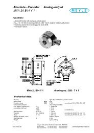
SINAMICS G110, frame size A (on the right with flat heat sink)<br />
SINAMICS G110, frame sizes B and C<br />
SINAMICS G110 is a frequency inverter with basic functions for<br />
a variety of industrial variable-speed drive applications.<br />
The particularly compact SINAMICS G110 inverter operates<br />
with voltage frequency control on single-phase supplies<br />
(200 V to 240 V).<br />
It is the ideal low-cost frequency inverter solution for the lower<br />
power range of the SINAMICS family.<br />
The following line-side power components are available for<br />
SINAMICS G110 inverters:<br />
EMC filters<br />
Line reactors<br />
Fuses<br />
Circuit-breakers<br />
The following accessories are also available:<br />
Operator panels<br />
Mounting accessories<br />
Commissioning tool<br />
The latest technical documentation (catalogs, dimensional<br />
drawings, certificates, user manuals and operating instructions)<br />
is available on the Internet at:<br />
http://www.siemens.com/<strong>sinamics</strong>-g110<br />
and also on CD-ROM CA 01 Vol. 2 “Planning” in the SD configurator,<br />
which can be ordered from the following address:<br />
http://www.siemens.com/automation/CA01<br />
2/2<br />
Siemens D 11.1· 2007<br />
© Siemens AG 2007<br />
■ Benefits<br />
7 Simple installation, parameterization, and commissioning<br />
7 Robust EMC design<br />
7 Large parameter range enables configurations for a wide<br />
range of applications<br />
7 Simple cable connection<br />
7 Scaleable functionality with analog and USS variants<br />
7 Low-noise motor operation resulting from high pulse<br />
frequency<br />
7 Status information and alarms via the optional BOP<br />
(Basic Operator Panel)<br />
7 Rapid copying of parameters via the optional BOP<br />
7 External options for PC communication and BOP<br />
7 Fast, repeatable digital input response time for rapidresponse<br />
applications<br />
7 Fine adjustment using a high-resolution 10-bit analog input<br />
(analog variants only)<br />
7 LED for status information<br />
7 Variants with internal EMC filter class A or B<br />
7 DIP switches for easy adaptation to 50 Hz or 60 Hz<br />
applications<br />
7 DIP switches for simple bus termination for the USS version<br />
(RS485)<br />
7 Bus-capable serial RS485 interface (USS variants only) enables<br />
integration in a networked drive system<br />
7 2/3-wire method (static/pulsated signals) for universal control<br />
via digital inputs<br />
7 Variable lower voltage limit in DC link to ensure controlled motor<br />
braking if the power fails<br />
Accessories (overview)<br />
BOP operator panel<br />
Adapter for installation on DIN rail<br />
(frame sizes A and B)<br />
PC inverter connection kit<br />
STARTER commissioning tool<br />
Line-side power components (overview)<br />
EMC filter class B with low leakage currents<br />
Additional EMC filter, class B<br />
Line reactors<br />
International standards<br />
Fulfills the requirements of the EU low-voltage guidelines<br />
CE mark<br />
Certified to UL and cUL<br />
c-tick
■ Application<br />
SINAMICS G110 is especially suited for use with pumps and<br />
fans, or as a drive in various industrial sectors, such as the food,<br />
textile and packaging industries, as well as for conveyor systems,<br />
factory gate and garage door operating mechanisms, and<br />
as a universal drive for moving billboards.<br />
■ Design<br />
The SINAMICS G110 inverter chassis units are equipped with<br />
a control and power module and provide CPM 110 inverters<br />
(Controlled Power Module) with a compact and efficient design.<br />
They operate with the latest IGBT technology and digital microprocessor<br />
control.<br />
The SINAMICS G110 inverter product range consists of the following<br />
variants and versions:<br />
The analog variant is available in the following versions:<br />
- Without EMC filter, with heat sink<br />
- Integrated EMC filter, class A/B, with heat sink<br />
- Without EMC filter, with flat heat sink (FSA only)<br />
- Integrated EMC filter, class B, with flat heat sink (FSA only).<br />
The USS variant (RS485) is available in the following versions:<br />
- Without EMC filter, with heat sink<br />
- Integrated EMC filter, class A/B, with heat sink<br />
- Without EMC filter, with flat heat sink (FSA only)<br />
- Integrated EMC filter, class B, with flat heat sink (FSA only).<br />
With housing size FSA, cooling is achieved through a heat sink<br />
and natural convection. The FSA design with flat heat sink offers<br />
space-saving and favorable heat dissipation since an additional<br />
heat sink can be installed outside the control cabinet. With housing<br />
sizes FSB and FSC, an integrated fan is used to cool the heat<br />
sink which has resulted in the compact design.<br />
The connections for all inverter variants are easily accessible<br />
and in the same location. To ensure optimum electromagnetic<br />
compatibility and easy connection, the line and motor connections<br />
are located on opposite sides (as with contactors). The<br />
control terminal block does not require screws to install it.<br />
The optional BOP (Basic Operator Panel) can be installed without<br />
the use of tools.<br />
© Siemens AG 2007<br />
SINAMICS G110<br />
Inverter chassis units 0.12 kW to 3 kW<br />
Controlled Power Modules<br />
■ Function<br />
Careful handling of the machine mechanical system due to a<br />
skip frequency band in case of resonance, parameterizable<br />
ramp up/ramp down times up to 650 s, ramp smoothing, as<br />
well as bringing the inverter into circuit on turning motor<br />
(flying start)<br />
Increased installation availability by automatic restart facility<br />
following power failure or fault<br />
Fast current limit (FCL) for trip-free operation in case of sudden<br />
load changes<br />
Programmable V/f characteristic (e.g. for synchronous<br />
motors)<br />
Fast DC and compound braking without external braking<br />
resistor<br />
Limitation of DC link voltage by means of the V DCmax controller<br />
Slip compensation, electronic motor potentiometer function<br />
and three fixed speed setpoints<br />
Configurable voltage boost for higher dynamic response<br />
when starting and accelerating<br />
Motor holding brake function to control an external mechanical<br />
brake<br />
Siemens D 11.1· 2007<br />
2/3<br />
2
2<br />
SINAMICS G110<br />
Inverter chassis units 0.12 kW to 3 kW<br />
Controlled Power Modules<br />
■ Technical specifications<br />
1) Applies to industrial control cabinet installations to NEC article 409/UL 508A. For further information, visit us on the Internet at:<br />
http://support.automation.siemens.com/WW/view/en/23995621<br />
2/4<br />
Siemens D 11.1· 2007<br />
Controlled Power Modules<br />
Power range 0.12 … 3.0 kW<br />
Line voltage 200…240V 1AC±10%<br />
Line frequency 47 … 63 Hz<br />
Output frequency 0 … 650 Hz<br />
cos ϕ ≥ 0.95<br />
Inverter efficiency<br />
with devices < 0.75 kW 90 … 94%<br />
with devices ≥ 0.75 kW ≥ 95%<br />
Overload capability Overload current 1.5 × rated output current (i.e. 150% overload) for 60 s,<br />
then 0.85 × rated output current for 240 s,<br />
cycle time 300 s<br />
Inrush current Less than rated input current<br />
© Siemens AG 2007<br />
Control methods Linear V/f characteristic (with parameterizable voltage boost);<br />
quadraticV/f characteristic;<br />
multipoint characteristic (parameterizable V/f characteristic)<br />
Pulse frequency 8 kHz (standard)<br />
2 … 16 kHz (in 2 kHz increments)<br />
Fixed frequencies 3, programmable<br />
Skipped frequency range 1, programmable<br />
Setpoint resolution 0.01 Hz digital<br />
0.01 Hz serial<br />
10 bit analog (motorized potentiometer 0.1 Hz)<br />
Digital inputs 3 programmable digital inputs, non-floating, PNP, SIMATIC-compatible<br />
Analog input (analog variant) 1, for setpoint (0 V to 10 V, scaleable or for use as 4th digital input)<br />
Digital output 1 isolated optocoupler output (24 V DC, 50 mA, ohmic, NPN type)<br />
Universal serial interface (USS variant) RS485, for operation with USS protocol<br />
Motor cable length, max.<br />
Shielded 25 m<br />
Unshielded 50 m<br />
Electromagnetic compatibility All devices with integrated EMC filter for drive systems in<br />
category C2 installations (limit value in accordance with EN 55011, class A, group 1) and<br />
category C3 installations (limit value in accordance with EN 55011, class A, group 2).<br />
All devices with an integrated EMC filter and shielded cables with a maximum length of 5 m also fulfill the<br />
limit values of EN 55011, class B.<br />
Braking DC braking, compound braking<br />
Degree of protection IP20<br />
Operating temperature -10…+40°C<br />
up to +50 °C with derating<br />
Storage temperature -40 … +70 °C<br />
Relative humidity 95% (non-condensing)<br />
Installation altitude Up to 1000 m above sea level without derating<br />
Rated output current<br />
at 4000 m above sea level: 90%<br />
Line voltage<br />
up to 2000 m above sea level: 100%<br />
at 4000 m above sea level: 75%<br />
Standard SCCR<br />
(Short Circuit Current Rating) 1)<br />
10 kA<br />
Protective functions for Undervoltage<br />
Overvoltage<br />
Ground fault<br />
Short-circuit<br />
Stall prevention<br />
Thermal motor protection I 2t Inverter overtemperature<br />
Motor overtemperature<br />
Compliance with standards UL, cUL, CE, c-tick<br />
CE mark Conformity with Low-Voltage Directive 73/23/EEC
■ Technical specifications (continued)<br />
Controlled Power Modules<br />
FSA<br />
≤ 0.37 kW<br />
FSA<br />
0.55 kW and<br />
0.75 kW<br />
SINAMICS G110<br />
Inverter chassis units 0.12 kW to 3 kW<br />
Controlled Power Modules<br />
Technical specifications for variant with flat heat sink<br />
The design with flat heat sink offers space-saving and favorable<br />
heat dissipation since an additional heat sink can be installed<br />
outside the control cabinet.<br />
Controlled Power Modules FSA with flat heat sink<br />
0.12 kW 0.25 kW 0.37 kW 0.55 kW 0.75 kW<br />
Operating temperature -10 … +50 °C -10 … +50 °C -10 … +50 °C -10 … +50 °C -10 … +40 °C<br />
Total power losses at full load and maximum<br />
operating temperature as specified<br />
22 W 28 W 36 W 43 W 54 W<br />
Line-side and control electronics losses 9 W 10 W 12 W 13 W 15 W<br />
Recommended thermal resistance of<br />
heat sink<br />
3.0 K/W 2.2 K/W 1.6 K/W 1.2 K/W 1.2 K/W<br />
Recommended output current 0.9 A 1.7 A 2.3 A 3.2 A 3.9 A<br />
Derating data and power loss<br />
Pulse frequency<br />
Output Power Rated output current in A<br />
loss at a pulse frequency of<br />
kW W 2 kHz 4 kHz 6 kHz 8 kHz 10 kHz 12 kHz 14 kHz 16 kHz<br />
0.12 22 0.9 0.9 0.9 0.9 0.9 0.9 0.9 0.9<br />
0.25 28 1.7 1.7 1.7 1.7 1.7 1.7 1.7 1.7<br />
0.37 36 2.3 2.3 2.3 2.3 2.3 2.3 2.3 2.3<br />
0.55 43 3.2 3.2 3.2 3.2 3.0 2.7 2.5 2.2<br />
0.75 (at 40 °C) 54 3.9 3.9 3.9 3.9 3.6 3.3 3.0 2.7<br />
0.75 54 3.2 3.2 3.2 3.2 3.0 2.7 2.5 2.2<br />
1.1 86 6.0 6.0 6.0 6.0 5.9 5.7 5.6 5.4<br />
1.5 (at 40 °C) 118 7.8 7.8 7.8 7.8 7.6 7.4 7.2 7.0<br />
1.5 118 6.0 6.0 6.0 6.0 5.9 5.7 5.6 5.4<br />
2.2 174 11.0 11.0 11.0 11.0 10.8 10.5 10.2 9.9<br />
3.0 (at 40 °C) 210 13.6 13.6 13.6 13.6 13.3 12.9 12.6 12.3<br />
3.0 210 11.0 11.0 11.0 11.0 10.8 10.5 10.2 9.9<br />
The current data apply to an ambient temperature of 50 °C unless<br />
specified otherwise.<br />
© Siemens AG 2007<br />
FSA<br />
≤ 0.37 kW<br />
with flat heat<br />
sink<br />
FSA<br />
0.55 kW and<br />
0.75 kW<br />
with flat heat<br />
sink<br />
FSB<br />
1.1 kW and<br />
1.5 kW<br />
FSC<br />
2.2 kW<br />
Dimensions<br />
(without accessories)<br />
Width 90 90 90 90 140 184 184<br />
Height 150 150 150 150 160 181 181<br />
Depth<br />
Weight, approx.<br />
116 131 101 101 142 152 152<br />
Without filter 0.7 0.8 0.6 0.7 1.4 1.9 2.0<br />
with filter 0.8 0.9 0.7 0.8 1.5 2.1 2.2<br />
Siemens D 11.1· 2007<br />
FSC<br />
3.0 kW<br />
2/5<br />
2
2<br />
SINAMICS G110<br />
Inverter chassis units 0.12 kW to 3 kW<br />
Controlled Power Modules<br />
■ Technical specifications (continued)<br />
Compliance with standards<br />
CE mark<br />
The SINAMICS G110 inverters meet the requirements of the<br />
Low-Voltage Directive 73/23/EEC.<br />
Low-voltage directive<br />
The inverters comply with the following standards listed in the<br />
EU gazette:<br />
EN 60204<br />
Safety of machinery, electrical equipment of machines<br />
EN 61800-5-1<br />
Electrical power drive systems with variable speed – Part 5-1:<br />
Requirements regarding safety – electrical, thermal, and energy<br />
requirements<br />
UL listing<br />
Converter devices in UL category NMMS certified to UL and<br />
cUL, in compliance with UL508C. UL list number E121068.<br />
For use in pollution degree 2 environment.<br />
On the Internet at http://www.ul.com<br />
Machine directive<br />
The inverters are suitable for installation in machines. Compliance<br />
with the machine directive 89/392/EEC requires a separate<br />
certificate of conformity. This must be provided by the plant constructor<br />
or the installer of the machine.<br />
EMC directive<br />
EN 61800-3<br />
Variable-speed electric drives<br />
Part 3: EMC product standard including specific test methods<br />
The modified EMC product standard EN 61800-3 for electrical<br />
drive systems is valid since 07/01/2005. The transition period for<br />
the predecessor standard EN 61800-3/A11 from February 2001<br />
ends on October 1, 2007. The following information applies to<br />
the SINAMICS G110 frequency inverters from Siemens:<br />
The EMC product standard EN 61800-3 does not apply directly<br />
to a frequency inverter but to a PDS (Power Drive System),<br />
which comprises the complete circuitry, motor and cables<br />
in addition to the inverter.<br />
Frequency inverters are normally only supplied to experts for<br />
installation in machines or systems. A frequency inverter must,<br />
therefore, only be considered as a component which, on its<br />
own, is not subject to the EMC product standard EN 61800-3.<br />
The inverter’s Instruction Manual, however, specifies the conditions<br />
regarding compliance with the product standard if the<br />
frequency inverter is expanded to a PDS. The EMC directive<br />
in the EU is complied with for a PDS by observance of the<br />
product standard EN 61800-3. The frequency inverters on<br />
their own do not generally require identification according to<br />
the EMC directive.<br />
2/6<br />
Siemens D 11.1· 2007<br />
© Siemens AG 2007<br />
In the new EN 61800-3 of July 2005, a distinction is no longer<br />
made between “general availability” and “restricted availability”.<br />
Instead, different categories have been defined, C1 to C4,<br />
in accordance with the environment of the PDS at the operating<br />
site:<br />
- Category C1: Drive systems for rated voltages < 1000 V for<br />
use in environment 1<br />
- Category C2: Stationary drive systems not connected by<br />
means of a plug connector for rated voltages < 1000 V.<br />
When used in environment 1, the system must be installed<br />
and commissioned by personnel familiar with EMC requirements.<br />
A warning is required.<br />
- Category C3: Drive systems for rated voltages < 1000 V for<br />
exclusive use in the second environment. A warning is<br />
required.<br />
- Category C4: Drive systems for rated voltages ≥ 1000 V, for<br />
rated currents ≥ 400 A, or for use in complex systems in environment<br />
2 An EMC plan must be created.<br />
The EMC product standard EN 61800-3 also defines limit values<br />
for conducted interference and radiated interference for<br />
“environment 2” (= industrial power supply systems that do<br />
not supply households). These limit values are below the limit<br />
values of filter class A to EN 55011. Unfiltered inverters can be<br />
used in industrial environments as long as they are installed in<br />
a system that contains line filters on the higher-level infeed<br />
side.<br />
With SINAMICS G110, Power Drive Systems (PDS) that fulfill<br />
EMC product standard EN 61800-3 can be set up (see the<br />
setup instructions). The table “Overview of SINAMICS G110<br />
components and PDS categories” and the SINAMICS G110<br />
ordering documentation show which of the components can<br />
be installed directly in a PDS.<br />
A differentiation must be made between the product standards<br />
for electrical drive systems (PDS) of the range of standards<br />
EN 61800 (of which Part 3 covers EMC topics) and the<br />
product standards for the devices/systems/machines, etc.<br />
This will probably not result in any changes in the practical use<br />
of frequency inverters. Since frequency inverters are always<br />
part of a PDS and these are part of a machine, the machine<br />
manufacturer must observe various standards depending on<br />
their type and environment (e.g. EN 61000-3-2 for line harmonics<br />
and EN 55011 for radio interference). The product<br />
standard for PDS on its own is, therefore, either insufficient or<br />
irrelevant.<br />
Regarding the compliance of limit values for line harmonics,<br />
EMC product standard EN 61800-3 for PDS refers to compliance<br />
with EN 61000-3-2 and EN 61000-3-12.<br />
Regardless of the configuration with SINAMICS G110 and its<br />
components, the mechanical engineer can also implement<br />
other measures to ensure that the machine complies with the<br />
EU EMC directive. The EU EMC directive is generally fulfilled<br />
when the relevant EMC product standards are observed.<br />
If they are not available, the generic standards (e.g.<br />
DIN EN 61000-x-x) can be used instead. It is important that<br />
the conducted and emitted interference at the line connection<br />
point and outside the machine remain below the relevant limit<br />
values. Any suitable technical means can be used to ensure<br />
this.
Electromagnetic compatibility<br />
No impermissible electromagnetic radiation occurs if the installation<br />
guidelines specific to the product are correctly observed.<br />
SINAMICS G110<br />
Inverter chassis units 0.12 kW to 3 kW<br />
Controlled Power Modules<br />
■ Technical specifications (continued)<br />
Overview of SINAMICS G110 components and<br />
PDS categories<br />
Environment 1<br />
Category C1<br />
(Residential, Unfiltered devices and external filter class B with low leakage currents (shielded motor cable up to 5 m)<br />
commercial)<br />
Category C2<br />
Category C2<br />
All devices with integrated filter<br />
All devices with integrated filter<br />
(shielded motor cable up to 5 m)<br />
(shielded motor cable up to 5 m)<br />
or<br />
or<br />
All devices with integrated filter<br />
All devices with integrated filter<br />
(frame size FSA: up to 10 m;<br />
(frame size FSA: up to 10 m;<br />
FSB and FSC: shielded motor cable up to 25 m) FSB and FSC: shielded motor cable up to 25 m)<br />
+ warning<br />
or<br />
or<br />
All devices with integrated filter + external filter,<br />
All devices with integrated filter + external filter,<br />
class B (shielded motor cable up to 25 m)<br />
class B (shielded motor cable up to 25 m)<br />
Note: When devices with an integrated filter and a max.<br />
motor cable length of 5 m or external class B filters are<br />
used, this exceeds the requirements of EN 61800-3 by a<br />
considerable margin!<br />
Category C3<br />
All devices with integrated filter (frame size FSA: up to 10 m; FSB and FSC: shielded motor cable up to 25 m)<br />
or<br />
All devices with integrated filter + external filter, class B (shielded motor cable up to 25 m)<br />
A warning is required.<br />
Note: When devices with an integrated filter and external class B filters are used, this exceeds the requirements of<br />
EN 61800-3 by a considerable margin!<br />
Category C4<br />
Not applicable to SINAMICS G110<br />
EMC phenomenon<br />
Standard/test<br />
Noise emissions<br />
EN 61800-3<br />
(environment 1)<br />
ESD immunity<br />
EN 61000-4-2<br />
Electrical fields immunity<br />
EN 61000-4-3<br />
Burst interference immunity<br />
EN 61000-4-4<br />
Surge immunity<br />
EN 61000-4-5<br />
Immunity to RFI emissions, conducted<br />
EN 61000-4-6<br />
The table below lists the measured results for emissions of and<br />
immunity to interference for the SINAMICS G110 inverters.<br />
The inverters were installed according to the guidelines with<br />
shielded motor cables and shielded control cables.<br />
Relevant criteria Limit value<br />
Siemens D 11.1· 2007<br />
Environment 2<br />
Industrial<br />
Conducted via mains cable 150 kHz to 30 MHz Unfiltered devices: not tested<br />
All devices with internal/external filter:<br />
Depending on filter type and planned PDS<br />
installation:<br />
Category C1:<br />
limit complies with EN 55011, class B.<br />
Category C2:<br />
limit complies with EN 55011, class A, Group 1.<br />
All devices with an internal/external filter also fulfill<br />
the limit for category C3 installations.<br />
Limit complies with EN 55011, class A, group 2.<br />
Emitted by the drive 30 MHz to 1 GHz All devices<br />
limit complies with EN 55011, class A, Group 1<br />
ESD by air discharge Test level 3 8kV<br />
ESD by contact discharge Test level 3 6kV<br />
Electrical field applied to unit Test level 3<br />
80 MHz to 1 GHz<br />
10 V/m<br />
Applied to all cable<br />
terminations<br />
Test level 4 4kV<br />
Applied to mains cables Test level 3 2kV<br />
Applied to mains, motor and<br />
control cables<br />
© Siemens AG 2007<br />
Test level 3<br />
0.15 MHz to 80 MHz<br />
80% AM (1 kHz)<br />
10 V<br />
2/7<br />
2
2<br />
SINAMICS G110<br />
Inverter chassis units 0.12 kW to 3 kW<br />
Controlled Power Modules<br />
■ Selection and ordering data<br />
Output Rated<br />
input<br />
current<br />
(at 230 V)<br />
The current data apply to an ambient temperature of 50 °C unless<br />
specified otherwise.<br />
The last digit of the complete order number for the<br />
SINAMICS G110 inverters represents the release version. When<br />
ordering, a different digit from the one specified may be present<br />
as a result of further technical development.<br />
2/8<br />
Rated<br />
output<br />
current<br />
Siemens D 11.1· 2007<br />
Frame size Type SINAMICS G110<br />
without filter<br />
SINAMICS G110<br />
with integrated filter<br />
Filter class 1)<br />
With use of<br />
shielded cables<br />
with a max. cable<br />
length of<br />
kW hp A A (Frame size) Order No. Order No. 5 m 10 m 25 m<br />
0.12 0.16 2.3 0.9 FSA Analog 6SL3211-0AB11-2UA1 6SL3211-0AB11-2BA1 B A 2) 2)<br />
USS 6SL3211-0AB11-2UB1 6SL3211-0AB11-2BB1 B A 2) 2)<br />
Analog<br />
(with flat heat sink)<br />
USS<br />
(with flat heat sink)<br />
6SL3211-0KB11-2UA1 6SL3211-0KB11-2BA1 B A 2) 2)<br />
6SL3211-0KB11-2UB1 6SL3211-0KB11-2BB1 B A 2) 2)<br />
0.25 0.33 4.5 1.7 FSA Analog 6SL3211-0AB12-5UA1 6SL3211-0AB12-5BA1 B A 2) 2)<br />
USS 6SL3211-0AB12-5UB1 6SL3211-0AB12-5BB1 B A 2) 2)<br />
Analog<br />
(with flat heat sink)<br />
USS<br />
(with flat heat sink)<br />
6SL3211-0KB12-5UA1 6SL3211-0KB12-5BA1 B A 2) 2)<br />
6SL3211-0KB12-5UB1 6SL3211-0KB12-5BB1 B A 2) 2)<br />
0.37 0.5 6.2 2.3 FSA Analog 6SL3211-0AB13-7UA1 6SL3211-0AB13-7BA1 B A 2) 2)<br />
USS 6SL3211-0AB13-7UB1 6SL3211-0AB13-7BB1 B A 2) 2)<br />
Analog<br />
(with flat heat sink)<br />
USS<br />
(with flat heat sink)<br />
6SL3211-0KB13-7UA1 6SL3211-0KB13-7BA1 B A 2) 2)<br />
6SL3211-0KB13-7UB1 6SL3211-0KB13-7BB1 B A 2) 2)<br />
0.55 0.75 7.7 3.2 FSA Analog 6SL3211-0AB15-5UA1 6SL3211-0AB15-5BA1 B A 2) 2)<br />
USS 6SL3211-0AB15-5UB1 6SL3211-0AB15-5BB1 B A 2) 2)<br />
0.75 1.0 10.0 3.9<br />
(at 40 °C)<br />
Analog<br />
(with flat heat sink)<br />
USS<br />
(with flat heat sink)<br />
6SL3211-0KB15-5UA1 6SL3211-0KB15-5BA1 B A 2) 2)<br />
6SL3211-0KB15-5UB1 6SL3211-0KB15-5BB1 B A 2) 2)<br />
FSA Analog 6SL3211-0AB17-5UA1 6SL3211-0AB17-5BA1 B A 2) 2)<br />
USS 6SL3211-0AB17-5UB1 6SL3211-0AB17-5BB1 B A 2) 2)<br />
Analog<br />
(with flat heat sink)<br />
USS<br />
(with flat heat sink)<br />
6SL3211-0KB17-5UA1 6SL3211-0KB17-5BA1 B A 2) 2)<br />
6SL3211-0KB17-5UB1 6SL3211-0KB17-5BB1 B A 2) 2)<br />
1.1 1.5 14.7 6.0 FSB Analog 6SL3211-0AB21-1UA1 6SL3211-0AB21-1AA1 B A 2) A 2)<br />
USS 6SL3211-0AB21-1UB1 6SL3211-0AB21-1AB1 B A 2) A 2)<br />
1.5 2.0 19.7 7.8<br />
(at 40 °C)<br />
FSB Analog 6SL3211-0AB21-5UA1 6SL3211-0AB21-5AA1 B A 2) A 2)<br />
USS 6SL3211-0AB21-5UB1 6SL3211-0AB21-5AB1 B A 2) A 2)<br />
2.2 3.0 27.2 11.0 FSC Analog 6SL3211-0AB22-2UA1 6SL3211-0AB22-2AA1 B A 2) A 2)<br />
3.0 4.0 35.6 13.6<br />
(at 40 °C)<br />
1) The highlighted filter class is quoted on the rating plate of the inverter.<br />
© Siemens AG 2007<br />
USS 6SL3211-0AB22-2UB1 6SL3211-0AB22-2AB1 B A 2) A 2)<br />
FSC Analog 6SL3211-0AB23-0UA1 6SL3211-0AB23-0AA1 B A 2) A 2)<br />
USS 6SL3211-0AB23-0UB1 6SL3211-0AB23-0AB1 B A 2) A 2)<br />
All SINAMICS G110 inverters are supplied without an operator<br />
panel (OP). A BOP or other accessories must be ordered separately.<br />
2) Class B also with additional filter.
■ Accessories<br />
Basic operator panel (BOP)<br />
The BOP can be used to make individual parameter settings.<br />
Values and units are displayed via a 5-digit display.<br />
One BOP can be used for several inverters. It is plugged directly<br />
into the inverter.<br />
The BOP offers a function that enables you to copy parameters<br />
quickly and easily. A parameter set of one inverter can be saved<br />
and then loaded to another inverter.<br />
PC inverter connection kit<br />
For controlling and commissioning an inverter directly from a PC<br />
if the appropriate software (STARTER) has been installed.<br />
Isolated RS232 adapter module for a reliable point-to-point connection<br />
to a PC.<br />
The scope of supply includes a 9-pin Sub-D connector, an<br />
RS232 standard cable (3 m), and the STARTER commissioning<br />
tool on CD-ROM.<br />
Commissioning tool<br />
STARTER is a commissioning tool with a graphical interface for<br />
commissioning SINAMICS G110 frequency inverters in<br />
Windows NT/2000/XP Professional. It can be used to read,<br />
change, store, enter, and print parameter lists.<br />
1) STARTER commissioning tool also available on the Internet at<br />
http://www4.ad.siemens.de/WW/view/de/10804985/133100<br />
© Siemens AG 2007<br />
SINAMICS G110<br />
Inverter chassis units 0.12 kW to 3 kW<br />
Controlled Power Modules<br />
■ Selection and ordering data<br />
The accessories listed here are suitable for all SINAMICS G110<br />
inverters.<br />
Accessories Order No.<br />
BOP<br />
6SL3255-0AA00-4BA1<br />
(Basic Operator Panel)<br />
PC inverter connection kit<br />
incl. 9-pin Sub-D connector,<br />
standard RS232 cable (3 m), and<br />
STARTER commissioning tool on<br />
CD-ROM 1)<br />
6SL3255-0AA00-2AA1<br />
Adapter for DIN rail attachment<br />
Size 1 (FSA) 6SL3261-1BA00-0AA0<br />
Size 2 (FSB) 6SL3261-1BB00-0AA0<br />
Documentation CD,<br />
6SL3271-0CA00-0AG0<br />
with operating instructions,<br />
parameter list, and Getting Started<br />
guide<br />
STARTER commissioning tool<br />
on CD-ROM 1)<br />
6SL3072-0AA00-0AG0<br />
Siemens D 11.1· 2007<br />
2/9<br />
2
2<br />
SINAMICS G110<br />
Inverter chassis units 0.12 kW to 3 kW<br />
Controlled Power Modules<br />
■ Dimensional drawings<br />
Inverter FSA; 0.12 kW to 0.37 kW<br />
Inverter FSA; 0.55 kW to 0.75 kW<br />
Inverter FSA with flat heat sink; 0.12 kW to 0.75 kW<br />
2/10<br />
90 (3.54)<br />
79 (3.11)<br />
90 (3.54)<br />
79 (3.11)<br />
140 (5.51)<br />
140 (5.51)<br />
150 (5.91)<br />
150 (5.91)<br />
Siemens D 11.1· 2007<br />
116 (4.57)<br />
131 (5.16)<br />
90 (3.54)<br />
79 (3.11) 101(4.01)<br />
140 (5.51)<br />
150 (5.91)<br />
© Siemens AG 2007<br />
G_D011_EN_00028<br />
G_D011_EN_00029<br />
G_D011_EN_00030<br />
140 (5.51)<br />
127 (5.0)<br />
Inverter FSB; 1.1 kW to 1.5 kW<br />
184 (7.24)<br />
170 (6.70)<br />
Inverter FSC; 2.2 kW to 3.0 kW<br />
135 (5.31)<br />
160 (6.30)<br />
142 (5.59)<br />
With attached operator panel (BOP), the mounting depth is<br />
increased by 8 mm (0.31 inches).<br />
All dimensions in mm (values in brackets are in inches).<br />
140 (5.51)<br />
181 (7.13)<br />
152 (5.98)<br />
G_D011_EN_00031<br />
G_D011_EN_00032
■ Schematics<br />
General circuit diagram<br />
Analog variant<br />
Input voltage<br />
0 V to + 10 V<br />
AIN+ 9<br />
+ or<br />
- 0 V 10<br />
+<br />
-<br />
+<br />
24 V<br />
-<br />
USS variant<br />
24 V<br />
DIN0<br />
DIN1<br />
DIN2<br />
DIN3<br />
0 V<br />
9<br />
7<br />
3<br />
4<br />
5<br />
7<br />
or<br />
+10 V<br />
AIN+<br />
- 4,7 k ><br />
0 V<br />
DIN0<br />
DIN1<br />
DIN2<br />
8<br />
9<br />
10<br />
8<br />
9<br />
3<br />
2<br />
DOUT+<br />
24 V DC 50 mA<br />
1<br />
DOUT-<br />
For an additional digital input (DIN 3)<br />
external connections should be made:<br />
or<br />
P+<br />
N-<br />
DIN3<br />
24 V<br />
max. 30 V<br />
max. 5 mA<br />
4<br />
5<br />
6<br />
7<br />
9<br />
6<br />
A<br />
B<br />
0 V<br />
A<br />
D<br />
RS485<br />
+24 V (max. 50 mA)<br />
© Siemens AG 2007<br />
Basic Operator Panel (accessories)<br />
JOG<br />
CPU<br />
SINAMICS G110<br />
Inverter chassis units 0.12 kW to 3 kW<br />
60<br />
Hz<br />
50<br />
Hz<br />
Bus<br />
Termination<br />
OFF<br />
Controlled Power Modules<br />
200 V to 240 V 1 AC<br />
PE<br />
PE<br />
AC<br />
DC<br />
PE<br />
M<br />
3 ~<br />
FS1<br />
L1, L2/N<br />
DC<br />
AC<br />
U, V, W<br />
Siemens D 11.1· 2007<br />
DC+<br />
DC -<br />
G_D011_EN_00027<br />
2/11<br />
2
2<br />
SINAMICS G110<br />
Inverter chassis units 0.12 kW to 3 kW<br />
Starter kit<br />
■ Overview<br />
The SINAMICS G110 starter kit offers an easy introduction to<br />
variable-speed drives.<br />
Available in a stackable transport case, it contains:<br />
Inverter (0.75 kW) with analog input and integrated EMC<br />
filter<br />
BOP operator panel<br />
PC inverter connection kit<br />
Short description, operating instructions, and parameter list<br />
(hard copy, in German)<br />
STARTER commissioning tool on CD-ROM incl. operating instructions,<br />
parameter list, and Getting Started guide<br />
Screwdriver<br />
2/12<br />
Siemens D 11.1· 2007<br />
© Siemens AG 2007<br />
■ Selection and ordering data<br />
Starter kit<br />
0.75 kW, German<br />
Order No.<br />
6SL3200-0AB10-0AA0
■ Overview<br />
Integrated EMC filter<br />
Versions with integrated EMC filters class A and class B are<br />
available for the corresponding environments.<br />
Class A<br />
The requirements are fulfilled when shielded cables with a<br />
max. length of 10 m (for FSA) or 25 m (for FSB and FSC) are<br />
used. The limits comply with EN 55011 class A.<br />
Class B<br />
The requirements are fulfilled when shielded cables with a<br />
max. length of 5 m are used. The limits comply with EN 55011<br />
class B.<br />
An inverter with an integrated filter can be used with a 30 mA residual-current<br />
circuit-breaker and is only suitable for installations<br />
with fixed wiring.<br />
Inverters without filters, which are used with “filter class B with<br />
low leakage currents”, have a leakage current of < 3.5 mA (up to<br />
5 m shielded motor cable).<br />
Additional EMC filter, class B<br />
Available for inverters with an internal EMC filter.<br />
With this filter, the inverter complies with the emission standard<br />
EN 55011, class B.<br />
The requirements are fulfilled using shielded cables with a max.<br />
length of 25 m.<br />
Filter class B with low leakage currents<br />
With this filter, the inverter complies with emission standard<br />
EN 55011, class B. The leakage currents are reduced to<br />
16 A and ≤ 75 A per phase”, a permission<br />
to operate drives on the public low-voltage network must be<br />
obtained from the power supplier. For the harmonic currents, see<br />
the instruction manual.<br />
Siemens D 11.1· 2007<br />
2/13<br />
2
2<br />
SINAMICS G110<br />
Inverter chassis units 0.12 kW to 3 kW<br />
Line-side power components<br />
■ Selection and ordering data<br />
The line-side power components listed here must be selected in<br />
accordance with the inverter. EMC filters and line reactors are<br />
not suitable for base-type installation.<br />
The inverter and associated line-side power components have<br />
the same rated voltage.<br />
Output Filter class B with<br />
low leakage currents<br />
2/14<br />
Siemens D 11.1· 2007<br />
© Siemens AG 2007<br />
All line-side power components are certified to UL (with the exception<br />
of fuses). Fuses of type 3NA3 are recommended for<br />
European countries. Further information about the listed fuses<br />
and circuit-breakers can be found in Catalogs LV 1 and LV 1 T.<br />
UL-listed fuses such as the class NON fuse series from<br />
Bussmann are required for North American countries.<br />
Line reactor Additional EMC filter, Fuse Circuit-breakers<br />
class B<br />
kW hp Order No. Order No. Order No. Order No. Order No.<br />
Line-side power components for inverters without filter<br />
0.12 0.16 6SE6400-2FL01-0AB0 6SE6400-3CC00-4AB3 – 3NA3803 3RV1021-1DA10<br />
0.25 0.33 6SE6400-2FL01-0AB0 6SE6400-3CC00-4AB3 – 3NA3803 3RV1021-1FA10<br />
0.37 0.50 6SE6400-2FL01-0AB0 6SE6400-3CC01-0AB3 – 3NA3803 3RV1021-1HA10<br />
0.55 0.75 6SE6400-2FL01-0AB0 6SE6400-3CC01-0AB3 – 3NA3803 3RV1021-1JA10<br />
0.75 1.0 6SE6400-2FL01-0AB0 6SE6400-3CC01-0AB3 – 3NA3805 3RV1021-1KA10<br />
1.1 1.5 6SE6400-2FL02-6BB0 6SE6400-3CC02-6BB3 – 3NA3807 3RV1021-4BA10<br />
1.5 2.0 6SE6400-2FL02-6BB0 6SE6400-3CC02-6BB3 – 3NA3810 3RV1021-4CA10<br />
2.2 3.0 6SE6400-2FL02-6BB0 6SE6400-3CC02-6BB3 – 3NA3814 3RV1031-4EA10<br />
3.0 4.0 – 6SE6400-3CC03-5CB3 – 3NA3820 3RV1031-4FA10<br />
Line-side power components for inverters with integrated filter class A/B<br />
0.12 0.16 – 6SE6400-3CC00-4AB3 6SE6400-2FS01-0AB0 3NA3803 3RV1021-1DA10<br />
0.25 0.33 – 6SE6400-3CC00-4AB3 6SE6400-2FS01-0AB0 3NA3803 3RV1021-1FA10<br />
0.37 0.50 – 6SE6400-3CC01-0AB3 6SE6400-2FS01-0AB0 3NA3803 3RV1021-1HA10<br />
0.55 0.75 – 6SE6400-3CC01-0AB3 6SE6400-2FS01-0AB0 3NA3803 3RV1021-1JA10<br />
0.75 1.0 – 6SE6400-3CC01-0AB3 6SE6400-2FS01-0AB0 3NA3805 3RV1021-1KA10<br />
1.1 1.5 – 6SE6400-3CC02-6BB3 6SE6400-2FS02-6BB0 3NA3807 3RV1021-4BA10<br />
1.5 2.0 – 6SE6400-3CC02-6BB3 6SE6400-2FS02-6BB0 3NA3810 3RV1021-4CA10<br />
2.2 3.0 – 6SE6400-3CC02-6BB3 6SE6400-2FS02-6BB0 3NA3814 3RV1031-4EA10<br />
3.0 4.0 – 6SE6400-3CC03-5CB3 6SE6400-2FS03-5CB0 3NA3820 3RV1031-4FA10
© Siemens AG 2007<br />
SINAMICS G120<br />
Inverter chassis units<br />
0.37 kW to 90 kW<br />
3/2 SINAMICS G120 chassis units<br />
3/2 Overview<br />
3/3 Benefits<br />
3/3 Application<br />
3/4 Design<br />
3/5 Configuration<br />
3/6 Technical specifications<br />
3/7 CU240 Control Units<br />
3/7 Overview<br />
3/7 Selection and ordering data<br />
3/8 Design<br />
3/9 Integration<br />
3/13 Technical specifications<br />
3/15 Memory card for Control Units<br />
3/15 Overview<br />
3/15 Integration<br />
3/15 Selection and ordering data<br />
3/16 PM240 Power Modules<br />
3/16 Overview<br />
3/17 Integration<br />
3/19 Technical specifications<br />
3/24 Selection and ordering data<br />
3/25 Characteristic curves<br />
3/26 Dimensional drawings<br />
3/31 PM250 Power Modules<br />
3/31 Overview<br />
3/32 Integration<br />
3/34 Technical specifications<br />
3/38 Selection and ordering data<br />
3/39 Characteristic curves<br />
3/40 Dimensional drawings<br />
3/43 PM260 Power Modules<br />
3/43 Overview<br />
3/44 Integration<br />
3/45 Technical specifications<br />
3/48 Selection and ordering data<br />
3/48 Characteristic curves<br />
3/49 Dimensional drawings<br />
3/50 Line-side<br />
power components<br />
3/50 Line filters<br />
3/52 Line reactors<br />
3/55 Recommended line components<br />
3/57 DC link components<br />
3/57 Braking resistors<br />
3/59 Load-side<br />
power components<br />
3/59 Output reactors<br />
3/64 Supplementary<br />
system components<br />
3/64 Basic Operator Panel BOP<br />
3/64 PC inverter connection kit<br />
3/65 Brake Relay<br />
3/66 Safe Brake Relay<br />
3/67 Adapter for DIN rail<br />
attachment<br />
3/67 Shield connection kit<br />
3/68 NEMA1 mounting kit<br />
Siemens D 11.1 · 2007
3<br />
SINAMICS G120<br />
Inverter chassis units 0.37 kW to 90 kW<br />
SINAMICS G120 chassis units<br />
■ Overview<br />
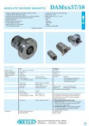
The new SINAMICS G120 series of frequency inverters is designed<br />
to provide precise and cost-effective speed/torque control<br />
of AC motors.<br />
3/2<br />
Siemens D 11.1 · 2007<br />
© Siemens AG 2007<br />
With different device versions (frame sizes FSA to FSF) in a<br />
power range of 0.37 kW to 90 kW, it is suitable for a wide variety<br />
of drive solutions.<br />
Examples of SINAMICS G120, frame sizes FSA, FSB and FSC; each with Power Module, Control Unit and Basic Operator Panel<br />
Examples of SINAMICS G120, frame sizes FSD, FSE and FSF; each with Power Module, Control Unit and Basic Operator Panel
© Siemens AG 2007<br />
SINAMICS G120<br />
Inverter chassis units 0.37 kW to 90 kW<br />
SINAMICS G120 chassis units<br />
■ Overview (continued)<br />
■ Benefits<br />
Modularity<br />
SINAMICS G120 is a modular converter system comprising a<br />
variety of functional units. The two main units are<br />
7 Modularity ensures flexibility for an advanced drive concept<br />
- Every development stage of a component can improve the<br />
existing drive system<br />
- Module replacement when system is running (hot swapping)<br />
the Control Unit (CU) and<br />
the Power Module (PM)<br />
- Pluggable terminals<br />
- The modules can be easily replaced, which makes the system<br />
extremely service friendly.<br />
The Control Unit controls and monitors the Power Module and<br />
the connected motor in several different modes. It supports<br />
communication with a local or central controller and monitoring<br />
devices.<br />
7 The safety functions make it easier to integrate drives into<br />
safety-oriented machines or plants<br />
7 Capable of communicating via PROFINET or PROFIBUS with<br />
PROFIdrive Profil 4.0<br />
The Power Module supplies the motor in the power range<br />
- Reduced number of interfaces<br />
0.37 kW to 90 kW. The Power Module is controlled by a micro- - Plant-wide engineering<br />
processor in the Control Unit. It features state-of-the-art IGBT - Easy to handle<br />
technology with pulse-width-modulated motor voltage and<br />
selectable pulse frequency. It also features a range of functions<br />
offering a high degree of protection for the Power Module and<br />
motor.<br />
7 The innovative circuit design (bidirectional input rectifier with<br />
“pared-down” DC link) allows the kinetic energy of a load to be<br />
fed back into the supply system when Power Modules PM250<br />
and PM260 are implemented. This feedback capability pro-<br />
Furthermore, a large number of additional components is available,<br />
such as:<br />
Basic Operator Panel (BOP) for parameterizing, diagnosing,<br />
controlling, and copying drive parameters<br />
Line filter, classes A and B<br />
Line reactors<br />
vides enormous potential for savings because generated energy<br />
no longer has to be converted into heat in a braking resistor<br />
7 Innovative SiC semiconductor technology ensures that when<br />
a PM260 Power Module is used, the inverter is more compact<br />
than a comparable standard inverter with an optional LC filter<br />
for the same output<br />
Braking resistors<br />
7 A new cooling concept and paint finish for the electronic mod-<br />
Output reactors<br />
ules increase robustness and service life<br />
Safety integrated<br />
7 Simple unit replacement and quick copying of parameters using<br />
the optional Basic Operator Panel or the optional MMC<br />
The SINAMICS G120 inverter chassis units are available in a memory card<br />
number of different variants for safety-oriented applications. All<br />
Power Modules are already designed for Safety Integrated.<br />
A Safety Integrated Drive can be created by combining a Power<br />
Module with the relevant Failsafe Control Unit.<br />
The SINAMICS G120 fail-safe frequency inverter provides four<br />
safety functions, certified in accordance with EN 954-1 Cat. 3<br />
and IEC 61508 SIL 2:<br />
Safe stop 1 (SS1)<br />
Safely limited speed (SLS)<br />
7 Low-noise motor operation resulting from high pulse frequency<br />
7 Compact, space-saving construction<br />
7 Software parameters for easy adaptation to 50 Hz or 60 Hz<br />
motors (IEC or NEMA motors)<br />
7 2/3-wire control (static/pulsated signals) for universal control<br />
via digital inputs<br />
7 Engineering and commissioning with uniform engineering<br />
tools such as SIZER, STARTER, and Drive ES: ensure rapid<br />
Safe brake control (SBC)<br />
engineering and easy commissioning – STARTER is inte-<br />
Safe torque off (STO)<br />
grated in STEP 7 with Drive ES Basic with all the advantages<br />
of central data storage and totally integrated communication<br />
Innovative cooling concept and paint finish of electronic<br />
modules<br />
7 Certified worldwide for compliance with CE, UL, cUL, C-tick,<br />
Safety Integrated IEC 61508 SIL 2<br />
The new cooling system and the paint finish for the electronic<br />
modules significantly increase the service life or useful life of the ■ Application<br />
device. These features are based on the following principles:<br />
SINAMICS G120 is ideal<br />
Disposal of all heat losses via an external heat sink<br />
as a universal drive in all industrial and commercial applica-<br />
<strong>Electronic</strong> modules not located in air duct<br />
tions<br />
Standardized convection cooling of Control Unit<br />
in the automotive, textiles, printing, and chemical industries<br />
All cooling air from the fan is directed through the heat sink<br />
for end-to-end applications, e.g. in conveyor systems<br />
STARTER drive/commissioning software<br />
The STARTER drive/commissioning software supports the commissioning<br />
and maintenance of SINAMICS G120 inverters. The<br />
operator guidance combined with comprehensive, user-friendly<br />
functions for the relevant drive solution allow you to commission<br />
the device quickly and easily.<br />
Siemens D 11.1 · 2007<br />
3/3<br />
3
3<br />
SINAMICS G120<br />
Inverter chassis units 0.37 kW to 90 kW<br />
0.37 kW to 90 kW<br />
■ Design<br />
The SINAMICS G120 inverter chassis units are modular frequency<br />
inverters for standard drives. Each SINAMICS G120<br />
comprises two operative units – the Power Module and Control<br />
Unit.<br />
Power Modules<br />
The following Power Modules are available for SINAMICS G120<br />
inverter chassis units:<br />
PM240 Power Modules<br />
PM240 Power Modules feature an integrated brake chopper and<br />
are designed for drives without energy recovery capability. Generator<br />
energy produced during braking is converted to heat via<br />
externally connected braking resistors.<br />
PM250 Power Modules<br />
PM250 Power Modules use an innovative circuit design which allows<br />
line-commutated energy recovery to the supply. This innovative<br />
circuit permits generator energy to be fed back into the<br />
supply system and therefore saves energy.<br />
PM260 Power Modules<br />
PM260 Power Modules also use an innovative circuit design<br />
which allows line-commutated energy recovery to the supply.<br />
This innovative circuit permits generator energy to be fed back<br />
into the supply system and, therefore, saves energy. The PM260<br />
Power Modules also have an integrated sine-wave filter that limits<br />
the rate of rise of voltage and the capacitive charge/discharge<br />
currents usually associated with inverter operation.<br />
Control Units<br />
The following Control Units and an MMC memory card are available<br />
as accessories for SINAMICS G120 inverter chassis units:<br />
CU240 Control Units<br />
The Control Unit performs closed-loop control functions for the<br />
inverter. In addition to control functions, the Control Unit can also<br />
perform other tasks which can be adapted to the relevant application<br />
by parameterization. A number of Control Units are available<br />
in different versions:<br />
CU240S<br />
CU240S DP<br />
CU240S DP-F<br />
CU240S PN<br />
CU240S PN-F (available soon)<br />
CU240E (available soon)<br />
MMC memory card<br />
The parameter settings for an inverter can be stored on the MMC<br />
memory card. When the plant is serviced, it is immediately ready<br />
for use again after, for example, replacement of the frequency inverter<br />
and transfer of the memory card data. The associated slot<br />
is located on top of the Control Unit.<br />
A large number of components for expanding the system is also<br />
available (e.g. line-side power components, DC-link components,<br />
load-side power components, and supplementary system<br />
components).<br />
3/4<br />
Siemens D 11.1 · 2007<br />
© Siemens AG 2007<br />
Line-side power components<br />
The following line-side power components are available for<br />
SINAMICS G120 inverter chassis units:<br />
Line filters<br />
The Power Module complies with a higher radio interference<br />
class with one additional line filter.<br />
Line reactors (for PM240 Power Modules only)<br />
A line reactor is needed for high system fault levels, partly to protect<br />
the actual inverter against excessive harmonic currents,<br />
and thus against overload, and partly to limit the system perturbation<br />
to the permitted values.<br />
Recommended line components<br />
This is a recommendation for further line-side components, such<br />
as fuses and circuit-breakers (line-side components must be dimensioned<br />
in accordance with IEC standards). Further information<br />
about the listed fuses and circuit-breakers can be found in<br />
Catalogs LV 1 and LV 1 T.<br />
DC link components<br />
The following DC-link components are available for SINAMICS<br />
G120 inverter chassis units:<br />
Braking resistors (for PM240 Power Modules only)<br />
Excess power in the DC link is dissipated via the braking resistor.<br />
The braking resistors are designed for use with PM240 Power<br />
Modules. They are equipped with an integrated brake chopper<br />
(electronic switch).<br />
Load-side power components<br />
The following load-side power components are available for<br />
SINAMICS G120 inverter chassis units. This means that during<br />
operation with output reactors or LC filters or sine-wave filters,<br />
longer, shielded motor cables are possible and the motor service<br />
life can be increased:<br />
Output reactors (for PM240 Power Modules only)<br />
Output reactors reduce the voltage loading on the motor windings.<br />
At the same time, the capacitive charge/discharge currents,<br />
which place an additional load on the power section when<br />
long motor cables are used, are reduced.<br />
LC filter and sine-wave filter (available soon)<br />
The LC filter/sine-wave filter limits the rate of rise of voltage and<br />
the capacitive charge/discharge currents usually associated<br />
with converter operation. An output reactor is not required.
© Siemens AG 2007<br />
SINAMICS G120<br />
Inverter chassis units 0.37 kW to 90 kW<br />
Siemens D 11.1 · 2007<br />
0.37 kW to 90 kW<br />
■ Design (continued)<br />
■ Configuration<br />
Availability as base components<br />
The following electronic configuration and engineering tools are<br />
The following line-side power components, DC-link components<br />
available for SINAMICS G120 inverter chassis units:<br />
and load-side power components are designed as base compo- SD configurator selection aid within the CA 01<br />
nents in the corresponding frame sizes:<br />
The interactive catalog CA 01 – the offline mall of Siemens Auto-<br />
Size<br />
mation and Drives (A&D) – contains over 100000 products with<br />
FSA FSB<br />
Line-side power components<br />
FSC FSD FSE FSF approximately 5 million potential drive system product variants.<br />
The SD configurator has been developed to facilitate selection<br />
of the correct motor and/or inverter from the wide spectrum of<br />
Line filter class A<br />
Line filter class B<br />
✓<br />
✓<br />
–<br />
✓<br />
–<br />
✓<br />
–<br />
–<br />
–<br />
–<br />
–<br />
–<br />
A&D SD products. The configurator is integrated in this catalog<br />
with the selection and configuration tools as a “selection help”<br />
on CD 2 “Configuring”.<br />
Line reactors<br />
(for PM240 Power<br />
✓ ✓ ✓ ✓ ✓ –<br />
SIZER configuration tool<br />
Modules only)<br />
The SIZER PC tool provides an easy-to-use means of configur-<br />
DC link components<br />
ing the SINAMICS and MICROMASTER 4 drive family. It provides<br />
Braking resistors ✓ ✓<br />
(for PM240 Power<br />
Modules only)<br />
Load-side power components<br />
– – – – support when setting up the technologies involved in the hardware<br />
and firmware components required for a drive task. SIZER<br />
supports the complete configuration of the drive system, from<br />
simple individual drives to complex multi-axis applications.<br />
Output reactors ✓ ✓ ✓ – – – STARTER drive/commissioning software<br />
(for PM240 Power<br />
Modules only)<br />
The STARTER drive/commissioning software provides menuguided<br />
assistance with commissioning, optimization and diag-<br />
Supplementary system components<br />
The following supplementary system components are available<br />
for SINAMICS G120 inverter chassis units:<br />
Basic Operator Panel BOP<br />
The Basic Operator Panel BOP can be plugged onto the Control<br />
Unit and can be used to commission drives, monitor drives in<br />
operation and input individual parameter settings. The BOP also<br />
provides a function for quick copying of parameters.<br />
nostics. STARTER is not only designed for use on SINAMICS<br />
drives but also for MICROMASTER4 units and frequency inverters<br />
for SIMATIC ET 200S FC distributed I/Os.<br />
Drive ES engineering system<br />
Drive ES is the engineering system used to integrate Siemens<br />
drive technology into the SIMATIC automation world easily, efficiently<br />
and cost-effectively in terms of communication, configuration<br />
and data management. The STEP 7 Manager user interface<br />
provides the basis for this procedure. A variety of software<br />
PC inverter connection kit<br />
For controlling and commissioning an inverter directly from a PC<br />
if the appropriate software (STARTER) has been installed.<br />
The STARTER commissioning tool is supplied with the PC<br />
inverter connection kit on CD-ROM.<br />
Brake Relay<br />
The Brake Relay allows the Power Module to be connected to an<br />
electromechanical motor brake, thereby allowing the motor<br />
brake to be driven directly by the Control Unit.<br />
Safe Brake Relay<br />
The Safe Brake Relay allows the Power Module to be connected<br />
to an electromechanical motor brake, allowing the brake to be<br />
directly and safely controlled by the Control Unit in accordance<br />
with EN 954-1, safety category 3 and IEC 61508 SIL 2.<br />
Adapter for DIN rail attachment<br />
The adapter for DIN rail attachment can be used to mount inverters<br />
of frame sizes FSA and FSB on DIN rails (2 units with a center-to-center<br />
distance of 100 mm).<br />
Shield connection kit<br />
The shield connection kit makes it easier to bond the shields of<br />
supply and control cables, offers mechanical strain relief and<br />
thus ensures optimum EMC performance.<br />
NEMA1 mounting kit<br />
The SINAMICS G120 inverter chassis units are designed to comply<br />
with type “UL OPEN”. The NEMA1 mounting kit is required to<br />
obtain a type 1 NEMA housing compliant with NEMA1 directives<br />
(NEMA 250-2003).<br />
packages, i.e. Drive ES Basic, Drive ES SIMATIC and<br />
Drive ES PCS 7, is available for SINAMICS.<br />
3/5<br />
3
3<br />
SINAMICS G120<br />
Inverter chassis units 0.37 kW to 90 kW<br />
0.37 kW to 90 kW<br />
■ Technical specifications<br />
Unless explicitly specified otherwise, the following technical<br />
specifications are valid for the following components of the<br />
SINAMICS G120 inverter chassis unit.<br />
Mechanical data<br />
Vibratory load<br />
Transport 1) Class 2M3 to EN 60068-2-6<br />
Operation Class 3M4 to EN 60068-2-6<br />
10 … 58 Hz: Constant<br />
deflection 0.075 mm<br />
58 … 200 Hz: Constant<br />
acceleration = 9.81 m/s 2 (1 g)<br />
Shock load<br />
Transport 1) Class 2M2 to EN 60068-2-27<br />
Operation Class 3M4 to EN 60068-2-27<br />
49 m/s2 (5 g)/30 ms<br />
Ambient conditions<br />
Protection class Class I (with protective conductor<br />
system) and class III (PELV) to<br />
EN 61800-5-1<br />
Shock protection according to EN 61800-5-1<br />
when used properly<br />
Permissible ambient and coolant<br />
temperature (air) during operation<br />
for line-side power components<br />
and Power Modules<br />
High overload (HO) -10…+50°C (14…122 °C)<br />
without derating,<br />
> 50 … 60 °C, see derating characteristics<br />
Light overload (LO) -10 … +40 °C (14 … 104 °C) without<br />
derating,<br />
> 40 … 60 °C, see derating characteristics<br />
Permissible ambient and coolant 0…50°C<br />
temperature (air) during opera- with CU240S DP-F: 0 … 45 °C<br />
tion for Control Units, additional up to 2000 m above sea level<br />
system components and DC-link<br />
components<br />
Climatic ambient conditions<br />
Storage 1) Class 1K3 to EN 60721-3-1<br />
Temperature -25 … +55 °C<br />
Transport 1) Class 2K4 to EN 60721-3-2<br />
Temperature -40 … +70 °C<br />
Max. air humidity 95% at 40 °C<br />
Operation Class 3K5 to EN 60721-3-3<br />
Condensation, splashwater and ice<br />
formation are not permitted<br />
(EN 60204, Part 1)<br />
Environmental class/harmful<br />
chemical substances<br />
Storage 1) Class 1C2 to EN 60721-3-1<br />
Transport 1) Class 2C2 to EN 60721-3-2<br />
Operation Class 3C2 to EN 60721-3-3<br />
Organic/biological influences<br />
Storage 1) Class 1B1 to EN 60721-3-1<br />
Transport 1) Class 2B1 to EN 60721-3-2<br />
Operation Class 3B1 to EN 60721-3-3<br />
Degree of contamination 2 to EN 61800-5-1<br />
1) In transport packaging.<br />
2) For further, general information, see also SINAMICS G110 sections “Technical<br />
specifications” and “Compliance with standards”.<br />
3/6<br />
Siemens D 11.1 · 2007<br />
© Siemens AG 2007<br />
Standards<br />
Standards conformance UL, cUL, CE, c-tick<br />
CE mark To Low-Voltage Directive 73/23/EEC<br />
and Machinery Directive 89/37/EEC<br />
EMC directive 2)<br />
Frame sizes FSB to FSF with in- Category C2<br />
tegrated line filter class A<br />
3) to EN 61800-3<br />
(corresponds to class A to<br />
EN 55011)<br />
Frame size FSA without inte- Category C2<br />
grated line filter, with additional<br />
line filter class A<br />
3) to EN 61800-3<br />
(corresponds to class A to<br />
EN 55011)<br />
Frame size FSA with additional Category C2<br />
line filter class A and with additional<br />
line filter class B<br />
3) to EN 61800-3<br />
(corresponds to class B to<br />
EN 55011)<br />
Frame sizes FSB and FSC with Category C2<br />
additional line filter class A and<br />
with additional line filter class B<br />
3) to EN 61800-3<br />
(corresponds to class B to<br />
EN 55011)<br />
Note: The EMC product standard<br />
EN 61800-3 does not apply<br />
directly to a frequency inverter<br />
but to a PDS (Power Drive System),<br />
which comprises the complete<br />
circuitry, motor and cables<br />
in addition to the inverter. The<br />
frequency inverters on their own<br />
do not generally require identification<br />
according to the EMC<br />
directive.<br />
3) With shielded motor cable up to 25 m.
■ Overview<br />
Example of CU240S DP-F Control Unit<br />
■ Selection and ordering data<br />
Communication Digital inputs<br />
Standard<br />
Digital inputs<br />
Failsafe<br />
© Siemens AG 2007<br />
SINAMICS G120<br />
Inverter chassis units 0.37 kW to 90 kW<br />
CU240 Control Units<br />
The Control Unit performs closed-loop control functions for the<br />
inverter. In addition to control functions, the Control Unit can also<br />
perform other tasks which can be adapted to the relevant application<br />
by parameterization. A number of Control Units are available<br />
in different versions:<br />
CU240S<br />
CU240S DP<br />
CU240S DP-F<br />
CU240S PN<br />
Digital outputs Encoder interfaces Designation Control Unit<br />
Order No.<br />
Standard<br />
RS485/USS 9 – 3 1 CU240S 6SL3244-0BA20-1BA0<br />
PROFIBUS DP 9 – 3 1 CU240S DP 6SL3244-0BA20-1PA0<br />
PROFINET 9 – 3 1 CU240S PN 6SL3244-0BA20-1FA0<br />
Failsafe for Safety Integrated<br />
PROFIBUS DP 6 2 3 1 CU240S DP-F 6SL3244-0BA21-1PA0<br />
Siemens D 11.1 · 2007<br />
3/7<br />
3
3<br />
SINAMICS G120<br />
Inverter chassis units 0.37 kW to 90 kW<br />
CU240 Control Units<br />
■ Design<br />
Example: Control Unit CU240S DP without terminal cover, with plug-in<br />
terminals<br />
Terminal No. Signal Features<br />
Digital inputs (DI) – standard<br />
5…8, DI0 … DI5 Freely programmable (isolated)<br />
16,17<br />
5.5 mA/24 V<br />
40 … 42 DI6 … DI8 Freely programmable (isolated)<br />
(with CU240S,<br />
CU240S DP,<br />
and<br />
CU240S PN<br />
only)<br />
5.5 mA/24 V<br />
Digital inputs (DI) – failsafe (for CU240S DP-F only)<br />
60 … 64 FDI0A Failsafe digital inputs, 2 channels<br />
(with<br />
FDI0B (redundant),<br />
CU240S DP-F FDI1A freely programmable (isolated)<br />
only)<br />
FDI1B 5.5 mA/24 V<br />
Digital outputs (DO)<br />
18 DO0, NC Relay output 1<br />
NC contact (0.5 A, 30 V DC)<br />
19 DO0, NO Relay output 1<br />
NO contact (0.5 A, 30 V DC)<br />
20 DO0, COM Relay output 1<br />
Common contact (0.5 A, 30 V DC)<br />
21 DO1, NO Relay output 2<br />
NO contact (0.5 A, 30 V DC)<br />
22 DO1, COM Relay output 2<br />
Common contact (0.5 A, 30 V DC)<br />
23 DO2, NC Relay output 3<br />
NC contact (0.5 A, 30 V DC)<br />
24 DO2, NO Relay output 3<br />
NO contact (0.5 A, 30 V DC)<br />
25 DO2, COM Relay output 3<br />
Common contact (0.5 A, 30 V DC)<br />
3/8<br />
Siemens D 11.1 · 2007<br />
© Siemens AG 2007<br />
Terminal No. Signal Features<br />
Analog inputs (AI)<br />
3 AI0+ 0…10V, -10…+10V, 0/2…10V, or<br />
4 AI0-<br />
0/4 … 20 mA<br />
10 AI1+ 0…10V, 0…20mA<br />
11 AI1-<br />
Analog outputs (AO)<br />
12 AO0+ Freely programmable (0/4 … 20 mA,<br />
0/2 … 10 V with 500 W load)<br />
13 AO0- M (GND)<br />
26 AO1+ Freely programmable<br />
(0/4 … 20 mA with 500 W load)<br />
27 AO1- M (GND)<br />
Encoder interface<br />
70 ENC AP Encoder AP – channel A non-negating<br />
input<br />
71 ENC AN Encoder AN – channel A negating<br />
input<br />
72 ENC BP Encoder BP – channel B non-negating<br />
input<br />
73 ENC BN Encoder BN – channel B negating<br />
input<br />
74 ENC ZP Encoder ZP – zero pulse non-negating<br />
input<br />
75 ENC ZN Encoder ZN – zero pulse negating<br />
input<br />
PTC/KTY interface<br />
14 PTC+ Positive PTC/KTY input<br />
15<br />
Power supply<br />
PTC- Negative PTC/KTY input<br />
33 ENC+ Isolated encoder power supply<br />
supply (+24 V with 100 mA, +5 V with 300 mA<br />
or > 30 V input by user), configured via<br />
DIP switches<br />
9 U24V Isolated user power supply<br />
+24 V with 100 mA<br />
28 U0V Isolated encoder power supply and user<br />
reference voltage<br />
1 +10 V Non-isolated, stabilized 10 V power supply<br />
for I/O – max. 10 mA<br />
2 0 V Power supply reference<br />
31 +24 V 24 V power supply input<br />
32 0 V 24 V power supply reference
■ Integration<br />
4.7 kOhm<br />
DI0<br />
5<br />
DI1<br />
6<br />
DI2<br />
7<br />
DI3<br />
8<br />
DI4<br />
16<br />
DI5<br />
17<br />
DI6<br />
DI7<br />
40<br />
41<br />
+<br />
DI8<br />
42<br />
-<br />
24 V<br />
28<br />
PTC/KTY<br />
0 to 20 mA<br />
max. 500 Ohm<br />
0 to 20 mA<br />
max. 500 Ohm<br />
Low voltage only<br />
(30 V, 500 mA)<br />
DO0<br />
DO1<br />
DO2<br />
1<br />
2<br />
3 AI0+<br />
4 AI0-<br />
10 AI1+<br />
11 AI1-<br />
5 DI0<br />
6 DI1<br />
7 DI2<br />
8 DI3<br />
16 DI4<br />
17 DI5<br />
40 DI6<br />
41 DI7<br />
42 DI8<br />
9 U24V<br />
28 U0V<br />
ENC+<br />
33 Line<br />
14 PTC+<br />
15 PTC-<br />
12 AO0+<br />
13 AO0-<br />
26 AO1+<br />
27 AO1-<br />
20 COM<br />
19 NO<br />
18 NC<br />
22 COM<br />
21 NO<br />
25 COM<br />
24 NO<br />
23 NC<br />
31 +24 V<br />
32 0V<br />
70 ENC AP<br />
71 ENC AN<br />
72 ENC BP<br />
73 ENC BN<br />
74 ENC ZP<br />
75 ENC ZN<br />
Connection diagram CU240S Control Unit<br />
+ 10 V<br />
0 V<br />
A A/<br />
D<br />
D D<br />
A A/<br />
D D<br />
Digital inputs<br />
A<br />
D<br />
D<br />
A<br />
A<br />
From<br />
external<br />
source<br />
Encoder interface<br />
MMC<br />
© Siemens AG 2007<br />
AI0<br />
SINAMICS G120<br />
Inverter chassis units 0.37 kW to 90 kW<br />
General I/O DIP switch<br />
0 to 20 mA<br />
ON<br />
AI1<br />
24 V encoder<br />
supply<br />
5 V encoder<br />
supply<br />
Encoder A<br />
termination<br />
Encoder B<br />
termination<br />
Encoder Z<br />
termination<br />
RS232/BOP interface<br />
OFF<br />
0 to 10 V<br />
PROFIBUS address DIP switch<br />
Control Unit<br />
CU240S<br />
PM-IF interface<br />
PROFIBUS<br />
interface<br />
SUB-D-type connector<br />
1 *<br />
2 *<br />
3 RxD/TxD-P<br />
4 TTL<br />
5 *<br />
6 5 V ±10%<br />
7 *<br />
8 RxD/TxD-N<br />
9 *<br />
G_D011_EN_00114<br />
CU240 Control Units<br />
BOP<br />
I<br />
O<br />
JOG<br />
* = Not connected<br />
FN<br />
P<br />
RS232 with<br />
PC to inverter<br />
connection kit<br />
Power Module<br />
Siemens D 11.1 · 2007<br />
3/9<br />
3
3<br />
SINAMICS G120<br />
Inverter chassis units 0.37 kW to 90 kW<br />
CU240 Control Units<br />
■ Integration (continued)<br />
Connection diagram CU240S DP Control Unit<br />
3/10<br />
4.7 kOhm<br />
DI0<br />
5<br />
DI1<br />
6<br />
DI2<br />
7<br />
DI3<br />
8<br />
DI4<br />
16<br />
DI5<br />
17<br />
DI6<br />
DI7<br />
40<br />
41<br />
+<br />
DI8<br />
42<br />
-<br />
24 V<br />
28<br />
PTC/KTY<br />
0 to 20 mA<br />
max. 500 Ohm<br />
0 to 20 mA<br />
max. 500 Ohm<br />
Low voltage only<br />
(30 V, 500 mA)<br />
DO0<br />
DO1<br />
DO2<br />
Siemens D 11.1 · 2007<br />
1<br />
2<br />
3 AI0+<br />
4 AI0-<br />
10 AI1+<br />
11 AI1-<br />
5 DI0<br />
6 DI1<br />
7 DI2<br />
8 DI3<br />
16 DI4<br />
17 DI5<br />
40 DI6<br />
41 DI7<br />
42 DI8<br />
9 U24V<br />
28 U0V<br />
ENC+<br />
33 Line<br />
14 PTC+<br />
15 PTC-<br />
12 AO0+<br />
13 AO0-<br />
26 AO1+<br />
27 AO1-<br />
20 COM<br />
19 NO<br />
18 NC<br />
22 COM<br />
21 NO<br />
25 COM<br />
24 NO<br />
23 NC<br />
31 +24 V<br />
32 0V<br />
70 ENC AP<br />
71 ENC AN<br />
72 ENC BP<br />
73 ENC BN<br />
74 ENC ZP<br />
75 ENC ZN<br />
+ 10 V<br />
0 V<br />
A A/<br />
D<br />
D D<br />
A A/<br />
D D<br />
Digital inputs<br />
A<br />
D<br />
D<br />
A<br />
A<br />
From<br />
external<br />
source<br />
Encoder interface<br />
MMC<br />
© Siemens AG 2007<br />
General I/O DIP switch<br />
0 to 20 mA<br />
ON<br />
AI0<br />
Bit 0<br />
AI1<br />
24 V encoder<br />
supply<br />
5 V encoder<br />
supply<br />
Encoder A<br />
termination<br />
Encoder B<br />
termination<br />
Encoder Z<br />
termination<br />
OFF<br />
0 to 10 V<br />
PROFIBUS address DIP switch<br />
ON (1) (2) (4) (8) (16) (32) (64)<br />
OFF<br />
Bit 1<br />
Bit 2<br />
Bit 3<br />
Bit 4<br />
BOP interface<br />
Bit 5<br />
Bit 6<br />
Control Unit<br />
CU240S DP<br />
PM-IF interface<br />
PROFIBUS<br />
interface<br />
SUB-D-type connector<br />
1 Shield<br />
2 U0V<br />
3 RxD/TxD-P<br />
4 CNTR-P<br />
5 DGND<br />
6 VP<br />
7 U24V<br />
8 RxD/TxD-N<br />
9 *<br />
G_D011_EN_00101<br />
BOP<br />
I<br />
O<br />
JOG<br />
* = Not connected<br />
FN<br />
P<br />
RS232 with<br />
PC to inverter<br />
connection kit<br />
Power Module
■ Integration (continued)<br />
4.7 kOhm<br />
DI0<br />
5<br />
DI1<br />
6<br />
DI2<br />
7<br />
DI3<br />
8<br />
DI4<br />
16<br />
DI5<br />
17<br />
DI6<br />
DI7<br />
40<br />
41<br />
+<br />
DI8<br />
42<br />
-<br />
24 V<br />
28<br />
PTC/KTY<br />
0 to 20 mA<br />
max. 500 Ohm<br />
0 to 20 mA<br />
max. 500 Ohm<br />
Low voltage only<br />
(30 V, 500 mA)<br />
paired<br />
paired<br />
DO0<br />
DO1<br />
DO2<br />
1<br />
2<br />
3 AI0+<br />
4 AI0-<br />
10 AI1+<br />
11 AI1-<br />
5 DI0<br />
6 DI1<br />
7 DI2<br />
8 DI3<br />
16 DI4<br />
17 DI5<br />
9 U24V<br />
60 DI1A<br />
61 DI1B<br />
62 DI2A<br />
63 DI2B<br />
28 U0V<br />
ENC+<br />
33 Line<br />
14 PTC+<br />
15 PTC-<br />
12 AO0+<br />
13 AO0-<br />
26 AO1+<br />
27 AO1-<br />
20 COM<br />
19 NO<br />
18 NC<br />
22 COM<br />
21 NO<br />
25 COM<br />
24 NO<br />
23 NC<br />
31 +24 V<br />
32 0V<br />
70 ENC AP<br />
71 ENC AN<br />
72 ENC BP<br />
73 ENC BN<br />
74 ENC ZP<br />
75 ENC ZN<br />
+ 10 V<br />
0 V<br />
A A/<br />
Connection diagram CU240S DP-F Control Unit<br />
D<br />
D D<br />
A A/<br />
D D<br />
Standard<br />
digital inputs<br />
Safety<br />
digital inputs<br />
A<br />
D<br />
D<br />
A<br />
A<br />
From<br />
external<br />
source<br />
Encoder interface<br />
MMC<br />
© Siemens AG 2007<br />
DES<br />
AI0<br />
Bit 0<br />
SINAMICS G120<br />
Inverter chassis units 0.37 kW to 90 kW<br />
General I/O DIP switch<br />
0 to 20 mA<br />
ON<br />
AI1<br />
24 V encoder<br />
supply<br />
5 V encoder<br />
supply<br />
Encoder A<br />
termination<br />
Encoder B<br />
termination<br />
Encoder Z<br />
termination<br />
DES<br />
0 to 10 V<br />
PROFIBUS address DIP switch<br />
ON (1) (2) (4) (8) (16) (32) (64)<br />
Bit 1<br />
Bit 2<br />
Bit 3<br />
Bit 4<br />
RS232/BOP interface<br />
Bit 5<br />
Bit 6<br />
Control Unit<br />
CU240S DP-F<br />
PROFIBUS<br />
interface<br />
SUB-D-type connector<br />
PM-IF interface<br />
1 Shield<br />
2 U0V<br />
3 RxD/TxD-P<br />
4 CNTR-P<br />
5 DGND<br />
6 VP<br />
7 U24V<br />
8 RxD/TxD-N<br />
9 *<br />
G_D011_EN_00102a<br />
CU240 Control Units<br />
BOP<br />
I<br />
O<br />
JOG<br />
* = Not connected<br />
FN<br />
P<br />
RS232 with<br />
PC to inverter<br />
connection kit<br />
Power Module<br />
Siemens D 11.1 · 2007<br />
3/11<br />
3
3<br />
SINAMICS G120<br />
Inverter chassis units 0.37 kW to 90 kW<br />
CU240 Control Units<br />
■ Integration (continued)<br />
Connection diagram CU240S DP Control Unit<br />
3/12<br />
4.7 kOhm<br />
DI0<br />
5<br />
DI1<br />
6<br />
DI2<br />
7<br />
DI3<br />
8<br />
DI4<br />
16<br />
DI5<br />
17<br />
DI6<br />
DI7<br />
40<br />
41<br />
+<br />
DI8<br />
42<br />
-<br />
24 V<br />
28<br />
PTC/KTY<br />
0 to 20 mA<br />
max. 500 Ohm<br />
0 to 20 mA<br />
max. 500 Ohm<br />
Low voltage only<br />
(30 V, 500 mA)<br />
DO0<br />
DO1<br />
DO2<br />
Siemens D 11.1 · 2007<br />
1<br />
2<br />
3 AI0+<br />
4 AI0-<br />
10 AI1+<br />
11 AI1-<br />
5 DI0<br />
6 DI1<br />
7 DI2<br />
8 DI3<br />
16 DI4<br />
17 DI5<br />
40 DI6<br />
41 DI7<br />
42 DI8<br />
9 U24V<br />
28 U0V<br />
ENC+<br />
33 Line<br />
14 PTC+<br />
15 PTC-<br />
12 AO0+<br />
13 AO0-<br />
26 AO1+<br />
27 AO1-<br />
20 COM<br />
19 NO<br />
18 NC<br />
22 COM<br />
21 NO<br />
25 COM<br />
24 NO<br />
23 NC<br />
31 +24 V<br />
32 0V<br />
70 ENC AP<br />
71 ENC AN<br />
72 ENC BP<br />
73 ENC BN<br />
74 ENC ZP<br />
75 ENC ZN<br />
+ 10 V<br />
0 V<br />
A A/<br />
D<br />
D D<br />
A A/<br />
D D<br />
Digital inputs<br />
A<br />
D<br />
D<br />
A<br />
A<br />
From<br />
external<br />
source<br />
Encoder interface<br />
MMC<br />
© Siemens AG 2007<br />
General I/O DIP switch<br />
0 to 20 mA<br />
ON<br />
OFF<br />
AI0<br />
0 to 10 V<br />
BOP interface<br />
AI1<br />
24 V encoder<br />
supply<br />
5 V encoder<br />
supply<br />
Encoder A<br />
termination<br />
Encoder B<br />
termination<br />
Encoder Z<br />
termination<br />
Control Unit<br />
CU240S PN<br />
PM-IF interface<br />
PROFIBUS<br />
interface<br />
RJ45<br />
1 TX+<br />
2 TX-<br />
3 RX+<br />
4 *<br />
5 *<br />
6 RX-<br />
7 *<br />
8 *<br />
G_D011_EN_00119<br />
BOP<br />
I<br />
O<br />
JOG<br />
* = Not connected<br />
FN<br />
P<br />
RS232 with<br />
PC to inverter<br />
connection kit<br />
Power Module
■ Technical specifications<br />
© Siemens AG 2007<br />
SINAMICS G120<br />
Inverter chassis units 0.37 kW to 90 kW<br />
CU240 Control Units<br />
Control Unit<br />
Control Unit<br />
Control Unit<br />
Control Unit<br />
CU240S<br />
CU240S DP<br />
CU240S DP-F<br />
CU240S PN<br />
6SL3244-0BA20-1BA0 6SL3244-0BA20-1PA0 6SL3244-0BA21-1PA0 6SL3244-0BA20-1FA0<br />
Electrical data<br />
Operating voltage 24 V DC via the Power 24 V DC via the Power 24 V DC via the Power 24 V DC via the Power<br />
Module or an external Module or an external Module or an external Module or an external<br />
24 V DC supply 24 V DC supply 24 V DC supply 24 V DC supply<br />
Power loss<br />
Interfaces<br />
< 40 W < 40 W < 40 W < 40 W<br />
Digital inputs – standard 9 9 6 9<br />
Digital inputs – failsafe – – 2 –<br />
Digital outputs 3 3 3 3<br />
Analog inputs 2 2 2 2<br />
Both analog inputs can be configured as supplementary digital inputs if an additional function is required.<br />
Switching thresholds:<br />
0 → 1: Rated voltage 2 V<br />
1 → 0: Rated voltage 0.8 V<br />
Analog inputs are protected against inputs in a voltage range of ± 30 V and have a common-mode voltage<br />
in the ± 15 V range.<br />
Analog outputs 2 2 2 2<br />
Analog outputs have short-circuit protection, but are not isolated.<br />
Maximum output voltage = 10 V in current mode,<br />
maximum output current = 20 mA in voltage mode.<br />
The reaction time should equal approximately 1 ms with a load of maximum 10 kΩ in voltage mode.<br />
Bus interface RS485/USS PROFIBUS DP PROFIBUS DP,<br />
PROFIsafe<br />
PROFINET<br />
Encoder interfaces 1 1 1 1<br />
PTC/KTY interface ✓ ✓ ✓ ✓<br />
Brake Relay interface/Safe Brake Relay<br />
interface (connection via Power Module)<br />
✓ ✓ ✓ ✓<br />
MMC memory card slot ✓ ✓ ✓ ✓<br />
RS232/USS interface (connection via PC<br />
inverter connection kit)<br />
Safety functions<br />
✓ ✓ ✓ ✓<br />
Integral safety functions to Category 3 of – – Safe Stop 1<br />
–<br />
EN 954-1 and SIL2 of IEC 61508<br />
(SS1)<br />
Safely Limited Speed<br />
(SLS)<br />
Safe Brake Control<br />
(SBC)<br />
Safe Torque Off<br />
(STO)<br />
Open-loop and closed-loop control functions<br />
V/f linear/quadratic/parameterizable ✓ ✓ ✓ ✓<br />
V/f with flux current control (FCC) ✓ ✓ ✓ ✓<br />
Vector control, encoderless ✓ ✓ ✓ ✓<br />
Vector control with encoder ✓ ✓ ✓ ✓<br />
Torque control, encoderless ✓ ✓ ✓ ✓<br />
Torque control with encoder ✓ ✓ ✓ ✓<br />
Siemens D 11.1 · 2007<br />
3/13<br />
3
3<br />
SINAMICS G120<br />
Inverter chassis units 0.37 kW to 90 kW<br />
CU240 Control Units<br />
■ Technical specifications (continued)<br />
3/14<br />
Siemens D 11.1 · 2007<br />
Control Unit<br />
CU240S<br />
6SL3244-0BA20-1BA0<br />
© Siemens AG 2007<br />
Control Unit<br />
CU240S DP<br />
6SL3244-0BA20-1PA0<br />
Control Unit<br />
CU240S DP-F<br />
6SL3244-0BA21-1PA0<br />
Control Unit<br />
CU240S PN<br />
6SL3244-0BA20-1FA0<br />
Software functions<br />
Fixed frequencies 16, programmable 16, programmable 16, programmable 16, programmable<br />
Signal interconnection with BICO technology<br />
✓ ✓ ✓ ✓<br />
Automatic restart following line failure or<br />
operation fault<br />
✓ ✓ ✓ ✓<br />
Positioning deceleration ramp ✓ ✓ ✓ ✓<br />
Slip compensation ✓ ✓ ✓ ✓<br />
Free function blocks (FFB) for logic and<br />
arithmetic operations<br />
✓ ✓ ✓ ✓<br />
Ramp smoothing ✓ ✓ ✓ ✓<br />
3 switchable drive data sets ✓ ✓ ✓ ✓<br />
3 switchable command data sets (CDS)<br />
(manual/auto)<br />
✓ ✓ ✓ ✓<br />
Flying restart ✓ ✓ ✓ ✓<br />
JOG ✓ ✓ ✓ ✓<br />
Technology controller (PID) ✓ ✓ ✓ ✓<br />
Thermal motor protection ✓ ✓ ✓ ✓<br />
Thermal inverter protection ✓ ✓ ✓ ✓<br />
Setpoint specification ✓ ✓ ✓ ✓<br />
Motor identification ✓ ✓ ✓ ✓<br />
Motor holding brake ✓ ✓ ✓ ✓<br />
Vdcmax controller ✓ (with PM240 only) ✓ (with PM240 only) ✓ (with PM240 only) ✓ (with PM240 only)<br />
Kinetic buffering ✓ (with PM240 only) ✓ (with PM240 only) ✓ (with PM240 only) ✓ (with PM240 only)<br />
Braking functions<br />
DC injection braking<br />
Compound braking<br />
Dynamic braking with integrated brake<br />
chopper<br />
✓ (with PM240 only) ✓ (with PM240 only) ✓ (with PM240 only) ✓ (with PM240 only)<br />
Mechanical specifications and environmental operating conditions<br />
Degree of protection<br />
Signal cable cross-section<br />
IP20 IP20 IP20 IP20<br />
min. 0.05 mm2 (AWG30) 0.05 mm2 (AWG30) 0.05 mm2 (AWG30) 0.05 mm2 (AWG30)<br />
max. 2mm2 (AWG14) 2mm2 (AWG14) 2mm2 (AWG14) 2mm2 (AWG14)<br />
Operating temperature -10…+50°C<br />
-10…+50°C<br />
0…45°C<br />
-10…+50°C<br />
(14…122°F)<br />
(14…122°F)<br />
(32…113°F)<br />
(14…122°F)<br />
Storage temperature -40…+70°C<br />
-40…+70°C<br />
-40…+70°C<br />
-40…+70°C<br />
(-40 … +158 °F) (-40 … +158 °F) (-40 … +158 °F) (-40 … +158 °F)<br />
Relative humidity < 95% RH,<br />
< 95% RH,<br />
< 95% RH,<br />
< 95% RH,<br />
Dimensions<br />
non-condensing non-condensing non-condensing non-condensing<br />
Width 73 mm 73 mm 73 mm 73 mm<br />
Height 177 mm 177 mm 177 mm 177 mm<br />
Depth 63 mm 63 mm 63 mm 63 mm<br />
Weight, approx. 0.52 kg 0.52 kg 0.52 kg 0.52 kg
■ Overview<br />
The parameter settings for an inverter can be stored on the MMC<br />
memory card. When the plant is serviced, it is immediately ready<br />
for use again after, for example, replacement of the frequency inverter<br />
and transfer of the memory card data.<br />
Parameter settings can be written from the MMC memory card<br />
to the inverter or saved from the inverter to the MMC memory<br />
card.<br />
Up to 100 parameter sets can be stored.<br />
Supports standard commissioning without the use of additional<br />
commissioning tools (e.g. BOP and STARTER).<br />
How the MMC memory card is commissioned can be defined<br />
by the user (parameter p8458):<br />
- 0 = Parameter set 0 is never automatically downloaded from<br />
the MMC (“never”)<br />
- 1 = Parameter set 0 is downloaded once after PowerOn<br />
(“once”)<br />
- 2 = Parameter set 0 is always downloaded once after Power<br />
On (“always”)<br />
Note:<br />
The MMC memory card is not required when the inverter is running.<br />
© Siemens AG 2007<br />
SINAMICS G120<br />
Inverter chassis units 0.37 kW to 90 kW<br />
■ Integration<br />
Memory card for Control Units<br />
Inserting the MMC memory card into the Control Unit<br />
Control Unit with inserted MMC memory card<br />
■ Selection and ordering data<br />
Order No.<br />
MMC memory card 6SL3254-0AM00-0AA0<br />
Siemens D 11.1 · 2007<br />
3/15<br />
3
3<br />
SINAMICS G120<br />
Inverter chassis units 0.37 kW to 90 kW<br />
PM240 Power Modules<br />
■ Overview<br />
PM240 Power Modules feature an integrated brake chopper to<br />
which an external braking resistor can be connected via terminals<br />
DCP/R1 and R2 (see DC-link components).<br />
The DC-link capacitance of the DC link is such that the PM240<br />
Power Module provides a sufficient control range for the DC-link<br />
voltage and is easily capable of handling applications such as<br />
kinetic buffering (maintenance of DC-link voltage through regenerative<br />
feedback to DC link of kinetic energy produced by the<br />
load) or controlled, safe deceleration after a power failure using<br />
kinetic energy produced by the load. Furthermore, several<br />
PM240 Power Modules can be electrically coupled by this<br />
method.<br />
The PM240 Power Module is also designed for safety-sensitive<br />
applications. In conjunction with a Safety Control Unit, the drive<br />
can be turned into a Safety Integrated Drive (see Control Units).<br />
The permissible cable lengths between inverter and motor are<br />
limited depending on cable type. Longer cables can be used if<br />
output reactors are connected (see load-side power components).<br />
3/16<br />
Siemens D 11.1 · 2007<br />
© Siemens AG 2007<br />
Line reactors are available for minimizing system perturbation<br />
(see line-side components).<br />
Frame size FSA of the PM240 Power Module is available only<br />
without integrated line filter to class A. A base filter for compliance<br />
with class A and another for compliance with class B are,<br />
therefore, provided (see line-side power components).<br />
Frame sizes FSB and FSC of the PM240 Power Module are available<br />
both with and without integrated line filter to class A. For<br />
compliance with class B, PM240 Power Modules with integrated<br />
line filter to class A must be fitted additionally with a base filter to<br />
class B (see line-side components).<br />
Power Modules with integrated line filter to class A are suitable<br />
only for connection to TN supply systems. Power Modules without<br />
integrated line filter can be connected to grounded (TN, TT)<br />
and non-grounded (IT) supply systems.
■ Integration<br />
PM240 Power Modules communicate with the Control Unit via<br />
the PM-IF interface.<br />
PM240 Power Modules feature the following interfaces as standard:<br />
PM-IF interface for connection of the PM240 Power Module<br />
and Control Unit. The PM240 Power Module also supplies<br />
power to the Control Unit by means of an integrated power<br />
pack<br />
Control Unit<br />
PE<br />
PM-IF Interface<br />
© Siemens AG 2007<br />
380 V to 480 V 3 AC<br />
L1<br />
L2<br />
L3<br />
Power Module<br />
PM240<br />
SINAMICS G120<br />
Inverter chassis units 0.37 kW to 90 kW<br />
PM240 Power Modules<br />
Terminals DCP/R1 and R2 for connection of an external braking<br />
resistor<br />
Motor connection made with screw terminals or screw studs<br />
Drive circuit for the Brake Relay or the Safe Brake Relay for<br />
controlling a holding brake<br />
2 x PE (protective earth) connections<br />
A B PE U2 V2 W2<br />
Connection diagram for PM240 Power Module with or without integrated line filter class A<br />
Availability as base components<br />
Frame size<br />
Many system components for PM240 Power Modules are designed<br />
as base components, that is, the component is mounted<br />
on the baseplate and the PM240 Power Module above it in a<br />
FSA FSB<br />
Line-side power components<br />
FSC FSD FSE FSF<br />
space-saving construction. Up to two base components can be<br />
mounted above one another.<br />
Line filter class A<br />
Line filter class B<br />
✓<br />
✓<br />
–<br />
✓<br />
–<br />
✓<br />
–<br />
–<br />
–<br />
–<br />
–<br />
–<br />
The following line-side power components, DC-link components<br />
and load-side power components are designed as base components<br />
in the corresponding frame sizes:<br />
Line reactors ✓<br />
DC link components<br />
✓ ✓ ✓ ✓ –<br />
Braking resistors ✓ ✓ – – – –<br />
Load-side power components<br />
Output reactors<br />
(motor reactors)<br />
✓ ✓ ✓ – – –<br />
C<br />
P<br />
U<br />
PE<br />
Brake<br />
Relay<br />
24 V DC brake<br />
U1/<br />
L1<br />
=<br />
V1/<br />
L2<br />
3 ~<br />
M<br />
3 ~<br />
W1/<br />
L3<br />
Line filter<br />
class A<br />
=<br />
3 ~<br />
G_D011_EN_00100<br />
DCP/R1<br />
R2<br />
DCN<br />
Braking<br />
resistor<br />
Siemens D 11.1 · 2007<br />
3/17<br />
3
3<br />
SINAMICS G120<br />
Inverter chassis units 0.37 kW to 90 kW<br />
PM240 Power Modules<br />
■ Integration (continued)<br />
The following diagram shows the basic layout of a PM240 Power<br />
Module with a line reactor as base component. The line-side reactors<br />
are equipped with terminals and the reactors at the Power<br />
Module end with a pre-assembled cable. In the final installation<br />
position, the mains terminals are at the top on frame sizes FSA<br />
to FSC, and at the bottom on frame sizes FSD to FSE.<br />
Basic layout of a PM240 Power Module with line reactor as base<br />
component<br />
If a line filter is installed in addition to the line reactor on frame<br />
size FSA, the components must be arranged as shown in the diagram<br />
below. In this case, the line connection is below.<br />
Power Modules of frame size FSB and higher are available with<br />
integrated line filters (an external line filter is not required in this<br />
case).<br />
Power Module PM240 frame size FSA with line reactor and line filter<br />
3/18<br />
Power<br />
Module<br />
Power<br />
Module<br />
Line<br />
filter<br />
Siemens D 11.1 · 2007<br />
Power supply<br />
Line<br />
reactor<br />
G_D211_EN_00078<br />
Line<br />
reactor<br />
G_D211_EN_00079<br />
Power supply<br />
© Siemens AG 2007<br />
Power<br />
Module<br />
Power<br />
supply<br />
Line<br />
reactor<br />
reactor<br />
G_D211_EN_00080 Motor<br />
to the motor<br />
Power Module PM240 frame size FSA with line reactor and motor reactor<br />
For configurations involving more than two base-type system<br />
components, e.g. line reactor + motor reactor + braking resistor,<br />
individual components must be mounted to the side of the Power<br />
Modules. In this instance, the line and motor reactors must be installed<br />
under the Power Module and the braking resistor to the<br />
side.<br />
Power<br />
Module<br />
Line<br />
filter<br />
Motor<br />
reactor<br />
Power supply<br />
to the motor<br />
reactor<br />
G_D211_EN_00081 Line
© Siemens AG 2007<br />
SINAMICS G120<br />
Inverter chassis units 0.37 kW to 90 kW<br />
■ Technical specifications<br />
General technical data<br />
PM240 Power Modules<br />
Line operating voltage 380…480V3AC ±10%<br />
Line requirements<br />
no restriction<br />
Line short circuit voltage uk Input frequency 47 … 63 Hz<br />
Output frequency<br />
Control type V/f 0…650Hz<br />
Control type Vector 0…200Hz<br />
Pulse frequency 4 kHz (standard),<br />
for higher pulse frequencies, see derating data<br />
Power factor 0.95<br />
Inverter efficiency 95 … 97%<br />
Control factor 93%<br />
Overload capability<br />
High overload<br />
1.5 × rated output current (i.e. 150% overload) for 57 s with a cycle time of 300 s<br />
(HO)<br />
2 × rated output current (i.e. 200% overload) for 3 s with a cycle time of 300 s<br />
Light overload<br />
1.1 × rated output current (i.e. 110% overload) for 57 s with a cycle time of 300 s<br />
(LO)<br />
1.5 × rated output current (i.e. 150% overload) for 3 s with a cycle time of 300 s<br />
Electromagnetic compatibility Optional line filter class A or B to EN 55011 available<br />
Possible braking methods DC injection braking<br />
Compound braking<br />
Dynamic braking with integrated brake chopper<br />
Degree of protection IP20<br />
Operating temperature<br />
High overload<br />
-10 … +50 °C (14 … 122°F) without derating,<br />
(HO)<br />
> 50 … 60 °C, see derating characteristics<br />
Light overload<br />
-10 … +40 °C (14 … 104 °F) without derating,<br />
(LO)<br />
> 40 … 60 °C, see derating characteristics<br />
Storage temperature -40 … +70 °C (-40 … +158 °F)<br />
Relative humidity < 95% RH, non-condensing<br />
Cooling Internal ventilator,<br />
power units with increased air cooling by built-in fans<br />
Installation altitude Up to 1000 m above sea level without derating,<br />
> 1000 m see derating characteristics<br />
Standard SCCR<br />
(Short Circuit Current Rating) 1)<br />
FSA, FSB, FSC: 10 kA<br />
FSD, FSE, FSF: 42 kA<br />
Protective functions Undervoltage<br />
Overvoltage<br />
Overload<br />
Ground fault<br />
Short-circuit<br />
Stall prevention<br />
Motor blocking protection<br />
Motor overtermperature<br />
Inverter overtemperature<br />
Parameter interlock<br />
Standards conformance UL, cUL, CE, c-tick<br />
CE mark To Low-Voltage Directive 73/23/EEC and Machinery Directive 98/37/EEC<br />
1) Applies to industrial control cabinet installations to NEC article 409/UL 508A. For further information, visit us on the Internet at:<br />
http://support.automation.siemens.com/WW/view/en/23995621<br />
PM240 Power Modules<br />
Siemens D 11.1 · 2007<br />
3/19<br />
3
3<br />
SINAMICS G120<br />
Inverter chassis units 0.37 kW to 90 kW<br />
PM240 Power Modules<br />
■ Technical specifications (continued)<br />
Line voltage<br />
380…480V 3AC<br />
Without integrated line filter 6SL3224-<br />
0BE13-7UA0<br />
3/20<br />
Siemens D 11.1 · 2007<br />
PM240 Power Modules<br />
6SL3224-<br />
0BE15-5UA0<br />
6SL3224-<br />
0BE17-5UA0<br />
6SL3224-<br />
0BE21-1UA0<br />
6SL3224-<br />
0BE21-5UA0<br />
Rated output current I 1)<br />
rated A 1.3 1.7 2.2 3.1 4.1<br />
1)<br />
Base load current IL A 1.3 1.7 2.2 3.1 4.1<br />
Base load current I 2)<br />
H A 1.3 1.7 2.2 3.1 4.1<br />
Output current Imax A 2.6 3.4 4.4 6.2 8.2<br />
Rated power based on IL kW 0.37 0.55 0.75 1.1 1.5<br />
Rated power based on IH kW 0.37 0.55 0.75 1.1 1.5<br />
Rated pulse frequency kHz 4 4 4 4 4<br />
Efficiency η 0.95 0.95 0.95 0.95 0.95<br />
Power loss kW 0.1 0.1 0.1 0.1 0.11<br />
Cooling air requirement m3 /s 0.005 0.005 0.005 0.005 0.005<br />
Sound pressure level dB(A) < 45 < 45 < 45 < 45 < 45<br />
24 V DC power supply<br />
for the Control Unit<br />
Rated input current<br />
A 1 1 1 1 1<br />
3)<br />
with line reactor A 1.4 1.8 2.3 3.2 4.3<br />
without line reactor A 1.7 2.1 2.6 3.9 4.9<br />
Max. length of cable to<br />
braking resistor<br />
m 15 15 15 15 15<br />
Line supply connection<br />
U1/L1, V1/L2, W1/L3<br />
Screw terminals Screw terminals Screw terminals Screw terminals Screw terminals<br />
Conductor cross-section mm 2 1…2.5 1…2.5 1…2.5 1…2.5 1…2.5<br />
Motor connection<br />
U2, V2, W2<br />
Screw terminals Screw terminals Screw terminals Screw terminals Screw terminals<br />
Conductor cross-section mm 2 1…2.5 1…2.5 1…2.5 1…2.5 1…2.5<br />
DC link connection, connection<br />
for braking resistor<br />
DCP/R1, DCN, R2<br />
Screw terminals Screw terminals Screw terminals Screw terminals Screw terminals<br />
Conductor cross-section mm 2 1…2.5 1…2.5 1…2.5 1…2.5 1…2.5<br />
PE connection On housing with On housing with On housing with On housing with On housing with<br />
Motor cable length<br />
M4 screw<br />
M4 screw<br />
M4 screw<br />
M4 screw<br />
M4 screw<br />
4) , max.<br />
Shielded m 50 50 50 50 50<br />
Unshielded m 100 100 100 100 100<br />
Degree of protection<br />
Dimensions<br />
IP20 IP20 IP20 IP20 IP20<br />
Width mm 73 73 73 73 73<br />
Height<br />
Depth<br />
mm 173 173 173 173 173<br />
- without Control Unit mm 145 145 145 145 145<br />
- with Control Unit mm 210 210 210 210 210<br />
Frame size FSA FSA FSA FSA FSA<br />
Weight, approx. kg 1.1 1.1 1.1 1.1 1.1<br />
1) The rated output current Irated and the base load current I L are based on<br />
the loading for light overload (light overload LO).<br />
2) The base load current IH is based on the loading for high overload (high<br />
overload HO).<br />
© Siemens AG 2007<br />
3) The input current depends on the motor load and line impedance. The<br />
input currents apply for a load representing the rated power (based on<br />
I rated) for a line impedance corresponding to u k = 1%. These current values<br />
without line reactor are quoted on the rating plate of the Power Module.<br />
4) Max. motor cable length 25 m (shielded) for PM240 Power Modules with<br />
integrated line filter to maintain the limit values of EN 61800-3 Category C2.
■ Technical specifications (continued)<br />
Line voltage<br />
380…480V 3AC<br />
Without integrated line filter<br />
With integrated line filter<br />
PM240 Power Modules<br />
6SL3224-<br />
0BE22-2UA0<br />
6SL3224-<br />
0BE22-2UA0<br />
6SL3224-<br />
0BE23-0UA0<br />
6SL3224-<br />
0BE23-0AA0<br />
SINAMICS G120<br />
Inverter chassis units 0.37 kW to 90 kW<br />
6SL3224-<br />
0BE24-0UA0<br />
6SL3224-<br />
0BE24-0AA0<br />
6SL3224-<br />
0BE25-5UA0<br />
6SL3224-<br />
0BE25-5AA0<br />
PM240 Power Modules<br />
6SL3224-<br />
0BE27-5UA0<br />
6SL3224-<br />
0BE27-5AA0<br />
Rated output current I 1)<br />
rated A 5.9 7.7 10.2 18 25<br />
Base load current I 1)<br />
L A 5.9 7.7 10.2 18 25<br />
2)<br />
Base load current IH A 5.9 7.7 10.2 13.2 29<br />
Output current Imax A 11.8 15.4 20.4 26.4 38<br />
Rated power based on IL kW 2.2 3 4 7.5 11<br />
Rated power based on IH kW 2.2 3 4 5.5 7.5<br />
Rated pulse frequency kHz 4 4 4 4 4<br />
Efficiency η 0.95 0.95 0.95 0.95 0.95<br />
Power loss kW 0.14 0.16 0.18 0.24 0.30<br />
Cooling air requirement m3 /s 0.024 0.024 0.024 0.055 0.055<br />
Sound pressure level dB(A) < 50 < 50 < 50 < 60 < 60<br />
24 V DC power supply<br />
for the Control Unit<br />
Rated input current<br />
A 1 1 1 1 1<br />
3)<br />
with line reactor A 6.1 8 10.4 18.7 26<br />
without line reactor A 7.6 10.2 13.4 21.9 31.5<br />
Max. length of cable to<br />
braking resistor<br />
m 15 15 15 15 15<br />
Line supply connection<br />
U1/L1, V1/L2, W1/L3<br />
Screw terminals Screw terminals Screw terminals Screw terminals Screw terminals<br />
Conductor cross-section mm 2 1…6 1…6 1…6 2.5…10 2.5…10<br />
Motor connection<br />
U2, V2, W2<br />
Screw terminals Screw terminals Screw terminals Screw terminals Screw terminals<br />
Conductor cross-section mm2 1…6 1…6 1…6 2.5…10 2.5…10<br />
DC link connection, connection<br />
for braking resistor<br />
DCP/R1, DCN, R2<br />
Screw terminals Screw terminals Screw terminals Screw terminals Screw terminals<br />
Conductor cross-section mm 2 1…6 1…6 1…6 2.5…10 2.5…10<br />
PE connection On housing with On housing with On housing with On housing with On housing with<br />
Motor cable length<br />
M5 screw<br />
M5 screw<br />
M5 screw<br />
M5 screw<br />
M5 screw<br />
4) , max.<br />
Shielded m 50 50 50 50 50<br />
Unshielded m 100 100 100 100 100<br />
Degree of protection<br />
Dimensions<br />
IP20 IP20 IP20 IP20 IP20<br />
Width mm 153 153 153 189 189<br />
Height<br />
Depth<br />
mm 270 270 270 334 334<br />
- without Control Unit mm 165 165 165 185 185<br />
- with Control Unit mm 230 230 230 250 250<br />
Frame size FSB FSB FSB FSC FSC<br />
Weight, approx. kg 4 4 4 7 7<br />
1) The rated output current Irated and the base load current I L are based on<br />
the loading for light overload (light overload LO).<br />
2) The base load current IH is based on the loading for high overload (high<br />
overload HO).<br />
© Siemens AG 2007<br />
3) The input current depends on the motor load and line impedance. The<br />
input currents apply for a load representing the rated power (based on<br />
I rated) for a line impedance corresponding to u k = 1%. These current values<br />
without line reactor are quoted on the rating plate of the Power Module.<br />
4) Max. motor cable length 25 m (shielded) for PM240 Power Modules with<br />
integrated line filter to maintain the limit values of EN 61800-3 Category C2.<br />
Siemens D 11.1 · 2007<br />
3/21<br />
3
3<br />
SINAMICS G120<br />
Inverter chassis units 0.37 kW to 90 kW<br />
PM240 Power Modules<br />
■ Technical specifications (continued)<br />
Line voltage<br />
380…480V 3AC<br />
Without integrated line filter<br />
With integrated line filter<br />
3/22<br />
Siemens D 11.1 · 2007<br />
PM240 Power Modules<br />
6SL3224-<br />
0BE31-1UA0<br />
6SL3224-<br />
0BE31-1AA0<br />
6SL3224-<br />
0BE31-5UA0<br />
6SL3224-<br />
0BE31-5AA0<br />
6SL3224-<br />
0BE31-8UA0<br />
6SL3224-<br />
0BE31-8AA0<br />
6SL3224-<br />
0BE32-2UA0<br />
6SL3224-<br />
0BE32-2AA0<br />
6SL3224-<br />
0BE33-0UA0<br />
6SL3224-<br />
0BE33-0AA0<br />
Rated output current I 1)<br />
rated A 32 38 45 60 75<br />
Base load current I 1)<br />
L A 32 38 45 60 75<br />
2)<br />
Base load current IH A 26 32 38 45 60<br />
Output current Imax A 52 64 76 90 124<br />
Rated power based on IL kW 15 18.5 22 30 37<br />
Rated power based on IH kW 11 15 18.5 22 30<br />
Rated pulse frequency kHz 4 4 4 4 4<br />
Efficiency η 0.95 0.95 0.95 0.95 0.95<br />
Power loss kW 0.4 0.4 0.5 0.7 1<br />
Cooling air requirement m3 /s 0.055 0.055 0.055 0.055 2 x 0.055<br />
Sound pressure level dB(A) < 60 < 60 < 60 < 61 < 60<br />
24 V DC power supply<br />
for the Control Unit<br />
Rated input current<br />
A 1 1 1 1 1<br />
3)<br />
with line reactor A 33 40 47 63 78<br />
without line reactor A 39 46 53 72 88<br />
Max. length of cable to<br />
braking resistor<br />
m 15 15 15 15 15<br />
Line supply connection<br />
U1/L1, V1/L2, W1/L3<br />
Screw terminals M6 screw studs M6 screw studs M6 screw studs M6 screw studs<br />
Conductor cross-section mm2 2.5 … 10 10 … 35 10 … 35 10 … 35 10 … 35<br />
Motor connection<br />
U2, V2, W2<br />
Screw terminals M6 screw studs M6 screw studs M6 screw studs M6 screw studs<br />
Conductor cross-section mm 2 2.5 … 10 10 … 35 10 … 35 10 … 35 10 … 35<br />
DC link connection, connection<br />
for braking resistor<br />
DCP/R1, DCN, R2<br />
Screw terminals M6 screw studs M6 screw studs M6 screw studs M6 screw studs<br />
Conductor cross-section mm 2 2.5 … 10 10 … 35 10 … 35 10 … 35 10 … 35<br />
PE connection On housing with On housing with On housing with On housing with On housing with<br />
Motor cable length<br />
M5 screw<br />
M6 screw<br />
M6 screw<br />
M6 screw<br />
M6 screw<br />
4) , max.<br />
Shielded m 50 50 50 50 50<br />
Unshielded m 100 100 100 100 100<br />
Degree of protection<br />
Dimensions<br />
IP20 IP20 IP20 IP20 IP20<br />
Width<br />
Height<br />
mm 189 275 275 275 275<br />
- without integrated filter mm 334 419 419 419 499<br />
- with integrated filter<br />
Depth<br />
mm 334 512 512 512 635<br />
- without Control Unit mm 185 204 204 204 204<br />
- with Control Unit mm 250 260 260 260 260<br />
Frame size<br />
Weight, approx.<br />
FSC FSD FSD FSD FSE<br />
without integrated filter kg 7 15.9 15.9 15.9 19.8<br />
with integrated filter kg 7 19.3 19.3 19.3 27.1<br />
1) The rated output current Irated and the base load current I L are based on<br />
the loading for light overload (light overload LO).<br />
2) The base load current IH is based on the loading for high overload (high<br />
overload HO).<br />
© Siemens AG 2007<br />
3) The input current depends on the motor load and line impedance. The<br />
input currents apply for a load representing the rated power (based on<br />
I rated) for a line impedance corresponding to u k = 1%. These current values<br />
without line reactor are quoted on the rating plate of the Power Module.<br />
4) Max. motor cable length 25 m (shielded) for PM240 Power Modules with<br />
integrated line filter to maintain the limit values of EN 61800-3 Category C2.
■ Technical specifications (continued)<br />
Line voltage<br />
380…480V 3AC<br />
Without integrated line filter<br />
With integrated line filter<br />
PM240 Power Modules<br />
6SL3224-0BE33-7UA0<br />
6SL3224-0BE33-7AA0<br />
6SL3224-0BE34-5UA0<br />
6SL3224-0BE34-5AA0<br />
SINAMICS G120<br />
Inverter chassis units 0.37 kW to 90 kW<br />
6SL3224-0BE35-5UA0<br />
6SL3224-0BE35-5AA0<br />
PM240 Power Modules<br />
6SL3224-0BE37-5UA0<br />
6SL3224-0BE37-5AA0<br />
Rated output current I 1)<br />
rated A 90 110 145 178<br />
1)<br />
Base load current IL A 90 110 145 178<br />
Base load current I 2)<br />
H A 75 90 110 145<br />
Output current Imax A 150 180 220 290<br />
Rated power based on IL kW 45 55 75 90<br />
Rated power based on IH kW 37 45 55 75<br />
Rated pulse frequency kHz 4 4 4 4<br />
Efficiency η 0.95 0.95 0.95 0.95<br />
Power loss kW 1.3 1.5 2 2.4<br />
Cooling air requirement m3 /s 2 × 0.055 0.15 0.15 0.15<br />
Sound pressure level dB(A) < 62 < 60 < 60 < 65<br />
24 V DC power supply<br />
for the Control Unit<br />
Rated input current<br />
A 1 1 1 1<br />
3)<br />
with line reactor A 94 115 151 186<br />
without line reactor A 105 129 168 204<br />
Max. length of cable to<br />
braking resistor<br />
m 15 15 15 15<br />
Line supply connection<br />
U1/L1, V1/L2, W1/L3<br />
M6 screw studs M8 screw studs M8 screw studs M8 screw studs<br />
Max. conductor<br />
cross -section<br />
mm2 10 … 35 1 × 120 or 2 × 50 1 × 120 or 2 × 50 1 × 120 or 2 × 50<br />
Motor connection<br />
U2, V2, W2<br />
M6 screw studs M8 screw studs M8 screw studs M8 screw studs<br />
Max. conductor<br />
cross -section<br />
mm2 10 … 35 1 × 120 or 2 × 50 1 × 120 or 2 × 50 1 × 120 or 2 × 50<br />
DC link connection, connection<br />
for braking resistor<br />
DCP/R1, DCN, R2<br />
M6 screw studs M8 screw studs M8 screw studs M8 screw studs<br />
Max. conductor<br />
cross -section<br />
mm 2 10 … 35 1 × 120 or 2 × 50 1 × 120 or 2 × 50 1 × 120 or 2 × 50<br />
PE connection On housing with<br />
On housing with<br />
On housing with<br />
On housing with<br />
Motor cable length<br />
M6 screw<br />
M8 screw<br />
M8 screw<br />
M8 screw<br />
4) , max.<br />
Shielded m 50 50 50 50<br />
Unshielded m 100 100 100 100<br />
Degree of protection<br />
Dimensions<br />
IP20 IP20 IP20 IP20<br />
Width<br />
Height<br />
mm 275 350 350 350<br />
- without integrated filter mm 499 634 634 634<br />
- with integrated filter<br />
Depth<br />
mm 635 934 934 934<br />
- without Control Unit mm 204 316 316 316<br />
- with Control Unit mm 260 372 372 372<br />
Frame size<br />
Weight, approx.<br />
FSE FSF FSF FSF<br />
without integrated filter kg 19.8 50.7 50.7 50.7<br />
with integrated filter kg 27.1 66.7 66.7 66.7<br />
1) The rated output current Irated and the base load current I L are based on<br />
the loading for light overload (light overload LO).<br />
2) The base load current IH is based on the loading for high overload (high<br />
overload HO).<br />
© Siemens AG 2007<br />
3) The input current depends on the motor load and line impedance. The<br />
input currents apply for a load representing the rated power (based on<br />
I rated) for a line impedance corresponding to u k = 1%. These current values<br />
without line reactor are quoted on the rating plate of the Power Module.<br />
4) Max. motor cable length 25 m (shielded) for PM240 Power Modules with<br />
integrated line filter to maintain the limit values of EN 61800-3 Category C2.<br />
Siemens D 11.1 · 2007<br />
3/23<br />
3
3<br />
SINAMICS G120<br />
Inverter chassis units 0.37 kW to 90 kW<br />
PM240 Power Modules<br />
■ Selection and ordering data<br />
Rated output 1) Rated output<br />
current 2)<br />
Irated 3/24<br />
Siemens D 11.1 · 2007<br />
Power<br />
based on the<br />
base load current 3)<br />
Base load<br />
current 3)<br />
I H<br />
Frame size SINAMICS G120<br />
Power Module PM240<br />
without integrated<br />
line filter<br />
SINAMICS G120<br />
Power Module PM240<br />
with integrated<br />
line filter class A<br />
kW hp A kW hp A Order No. Order No.<br />
380…480V 3AC<br />
0.37 0.50 1.3 0.37 0.50 1.3 FSA 6SL3224-0BE13-7UA0 –<br />
0.55 0.75 1.7 0.55 0.75 1.7 FSA 6SL3224-0BE15-5UA0 –<br />
0.75 1.0 2.2 0.75 1.0 2.2 FSA 6SL3224-0BE17-5UA0 –<br />
1.1 1.5 3.1 1.1 1.5 3.1 FSA 6SL3224-0BE21-1UA0 –<br />
1.5 2.0 4.1 1.5 2.0 4.1 FSA 6SL3224-0BE21-5UA0 –<br />
2.2 3.0 5.9 2.2 3.0 5.9 FSB 6SL3224-0BE22-2UA0 6SL3224-0BE22-2AA0<br />
3.0 4.0 7.7 3.0 4.0 7.7 FSB 6SL3224-0BE23-0UA0 6SL3224-0BE23-0AA0<br />
4.0 5.0 10.2 4.0 5.0 10.2 FSB 6SL3224-0BE24-0UA0 6SL3224-0BE24-0AA0<br />
7.5 10 18 5.5 7.5 13.2 FSC 6SL3224-0BE25-5UA0 6SL3224-0BE25-5AA0<br />
11.0 15 25 7.5 10 19 FSC 6SL3224-0BE27-5UA0 6SL3224-0BE27-5AA0<br />
15.0 20 32 11.0 15 26 FSC 6SL3224-0BE31-1UA0 6SL3224-0BE31-1AA0<br />
18.5 25 38 15.0 20 32 FSD 6SL3224-0BE31-5UA0 6SL3224-0BE31-5AA0<br />
22 30 45 18.5 25 38 FSD 6SL3224-0BE31-8UA0 6SL3224-0BE31-8AA0<br />
30 40 60 22 30 45 FSD 6SL3224-0BE32-2UA0 6SL3224-0BE32-2AA0<br />
37 50 75 30 40 60 FSE 6SL3224-0BE33-0UA0 6SL3224-0BE33-0AA0<br />
45 60 90 37 50 75 FSE 6SL3224-0BE33-7UA0 6SL3224-0BE33-7AA0<br />
55 75 110 45 60 90 FSF 6SL3224-0BE34-5UA0 6SL3224-0BE34-5AA0<br />
75 100 145 55 75 110 FSF 6SL3224-0BE35-5UA0 6SL3224-0BE35-5AA0<br />
90 125 178 75 100 145 FSF 6SL3224-0BE37-5UA0 6SL3224-0BE37-5AA0<br />
1) Rated output based on the rated output current Irated . The rated output current<br />
I rated is based on the loading for light overload (light overload LO).<br />
2) The rated output current Irated is based on the loading for light overload<br />
(light overload LO). These current values are quoted on the rating plate of<br />
the Power Module.<br />
© Siemens AG 2007<br />
3) The base load current IH is based on the loading for high overload (high<br />
overload HO).
SINAMICS G120<br />
Inverter chassis units 0.37 kW to 90 kW<br />
PM240 Power Modules<br />
■ Characteristic curves<br />
Derating data<br />
Pulse frequency<br />
Rated output<br />
Rated output current in A<br />
at 400 V 3 AC<br />
at a switching frequency of<br />
kW hp 4kHz 6kHz 8kHz 10 kHz 12 kHz 14 kHz 16 kHz<br />
0.37 0.50 1.3 1.1 0.9 0.8 0.7 0.6 0.5<br />
0.55 0.75 1.7 1.4 1.2 1.0 0.9 0.8 0.7<br />
0.75 1.0 2.2 1.9 1.5 1.3 1.1 1.0 0.9<br />
1.1 1.5 3.1 2.6 2.2 1.9 1.6 1.4 1.2<br />
1.5 2.0 4.1 3.5 2.9 2.5 2.1 1.8 1.6<br />
2.2 3.0 5.9 5.0 4.1 3.5 3.0 2.7 2.4<br />
3.0 4.0 7.7 6.5 5.4 4.6 3.9 3.5 3.1<br />
4.0 5.0 10.2 8.7 7.1 6.1 5.1 4.6 4.1<br />
7.5 10 18.0 16.2 13.3 11.4 9.5 8.6 7.6<br />
11.0 15 25.0 22.1 18.2 15.6 13.0 11.7 10.4<br />
15.0 20 32.0 27.2 22.4 19.2 16.0 14.4 12.8<br />
18.5 25 38.0 32.3 26.6 22.8 19.0 17.1 15.2<br />
22.0 30 45.0 38.3 31.5 27.0 22.5 20.3 18.0<br />
30.0 40 62.0 52.7 43.4 37.2 31.0 27.9 24.8<br />
37.0 50 75.0 63.8 52.5 45.0 37.5 33.8 30.0<br />
45.0 60 90.0 76.5 63.0 54.0 45.0 40.5 36.0<br />
55.0 75 110.0 93.5 77.0 66.0 55.0 49.5 44.0<br />
75.0 100 145.0 123.3 101.5 87.0 72.5 65.3 58.0<br />
90.0 125 178.0 151.3 124.6 – – – –<br />
Ambient temperature<br />
Permissible<br />
output current<br />
100<br />
%<br />
75<br />
74<br />
50<br />
25<br />
-10 0 10 20 30 40 50 C° 60<br />
Ambient temperature<br />
High overload (HO) Light overload (LO)<br />
Installation altitude<br />
Permissible<br />
output current<br />
100<br />
%<br />
90<br />
80<br />
70<br />
60 G_D011_EN_00104<br />
0 1000 2000 3000 m 4000<br />
Installation altitude above sea level<br />
© Siemens AG 2007<br />
G_D011_EN_00111<br />
Permissible<br />
output current<br />
Permissible<br />
output current<br />
100<br />
%<br />
75<br />
66<br />
50<br />
25<br />
-10 0 10 20 30 40 50 C° 60<br />
Ambient temperature<br />
100<br />
%<br />
90<br />
80<br />
77<br />
70<br />
60<br />
0 1000 2000 3000 m 4000<br />
Installation altitude above sea level<br />
Siemens D 11.1 · 2007<br />
G_D011_EN_00110<br />
G_D011_EN_00105<br />
3/25<br />
3
3<br />
SINAMICS G120<br />
Inverter chassis units 0.37 kW to 90 kW<br />
PM240 Power Modules<br />
■ Dimensional drawings<br />
Power Module PM240 frame size FSA<br />
Fixing with 2 M4 studs, 2 M4 nuts,<br />
2 M4 washers<br />
Tightening torque: 2.5 Nm (22.1 lbf-in)<br />
Ventilation clearance required at top and bottom:<br />
100 mm (3.94 inches)<br />
Ventilation clearance required at sides: 30 mm (1.18 inches)<br />
Power Module PM240 frame size FSB<br />
Fixing with 4 M4 studs, 4 M4 nuts, 4 M4 washers<br />
Tightening torque: 2.5 Nm (22.1 lbf-in)<br />
Ventilation clearance required at top and bottom:<br />
100 mm (3.94 inches)<br />
Ventilation clearance required at sides: 40 mm (1.57 inches)<br />
3/26<br />
145 (5.71) 73 (2.87)<br />
Siemens D 11.1 · 2007<br />
173 (6.81)<br />
165 (6.5) 153 (6.02)<br />
270 (10.63)<br />
© Siemens AG 2007<br />
G_D011_EN_00091<br />
4.5<br />
(0.18)<br />
Drill<br />
pattern<br />
160 (6.3)<br />
When the Control Unit is plugged in, the mounting depth increases<br />
by 65 mm (2.56 inches) and the total depth by<br />
14 mm (0.55 inches).<br />
All dimensions in mm (values in brackets are in inches).<br />
133 (5.24)<br />
4.8 (0.19)<br />
Drill pattern<br />
G_D011_EN_00092<br />
258 (10.16)<br />
When the Control Unit is plugged in, the mounting depth increases<br />
by 65 mm (2.56 inches).<br />
All dimensions in mm (values in brackets are in inches).
■ Dimensional drawings (continued)<br />
185 (7.28) 189 (7.44)<br />
167 (6.57)<br />
Power Module PM240 frame size FSC<br />
Fixing with 4 M5 studs, 4 M5 nuts, 4 M5 washers<br />
Tightening torque: 2.5 Nm (22.1 lbf-in)<br />
Ventilation clearance required at top and bottom:<br />
100 mm (3.94 inches)<br />
Ventilation clearance required at sides: 50 mm (1.97 inches)<br />
334 (13.15)<br />
© Siemens AG 2007<br />
SINAMICS G120<br />
Inverter chassis units 0.37 kW to 90 kW<br />
5.5 (0.22)<br />
Drill pattern<br />
G_D011_EN_0093<br />
323 (12.72)<br />
PM240 Power Modules<br />
When the Control Unit is plugged in, the mounting depth increases<br />
by 65 mm (2.56 inches).<br />
All dimensions in mm (values in brackets are in inches).<br />
Siemens D 11.1 · 2007<br />
3/27<br />
3
3<br />
SINAMICS G120<br />
Inverter chassis units 0.37 kW to 90 kW<br />
PM240 Power Modules<br />
■ Dimensional drawings (continued)<br />
Power Module PM240 frame size FSD without line filter<br />
Power Module PM240 frame size FSD with integrated line filter class A<br />
Fixing with 4 M6 studs, 4 M6 nuts, 4 M6 washers<br />
Tightening torque: 6 Nm (53 lbf-in)<br />
Ventilation clearance required at top and bottom:<br />
300 mm (11.81 inches)<br />
Ventilation clearance required at front: 28 mm (1.1 inches)<br />
3/28<br />
204 (8.03) 275 (10.83)<br />
361 (14.21)<br />
204 (8.03) 275 (10.83)<br />
455 (17.91)<br />
Siemens D 11.1 · 2007<br />
© Siemens AG 2007<br />
419 (16.5)<br />
512 (20.16)<br />
8.5 (0.33)<br />
8.5 (0.33)<br />
235 (9.25)<br />
Drill pattern<br />
235 (9.25)<br />
Drill pattern<br />
G_D011_EN_00094<br />
G_D011_EN_00095<br />
When the Control Unit is plugged in, the mounting depth increases<br />
by 56 mm (2.2 inches).<br />
All dimensions in mm (values in brackets are in inches).<br />
325 (12.8)<br />
419 (16.5)<br />
11 (0.43)<br />
11 (0.43)
■ Dimensional drawings (continued)<br />
204 (8.03) 275 (10.83)<br />
Power Module PM240 frame size FSE without line filter<br />
441 (17.36)<br />
204 (8.03) 275 (10.83)<br />
577 (22.72)<br />
Power Module PM240 frame size FSE with integrated line filter class A<br />
Fixing with 4 M6 studs, 4 M6 nuts, 4 M6 washers<br />
Tightening torque: 6 Nm (53 lbf-in)<br />
Ventilation clearance required at top and bottom:<br />
300 mm (11.81 inches)<br />
Ventilation clearance required at front: 28 mm (1.1 inches)<br />
© Siemens AG 2007<br />
499 (19.65)<br />
635 (25)<br />
SINAMICS G120<br />
Inverter chassis units 0.37 kW to 90 kW<br />
8.5 (0.33)<br />
8.5 (0.33)<br />
235 (9.25)<br />
Drill pattern<br />
235 (9.25)<br />
Drill pattern<br />
G_D011_EN_00096<br />
G_D011_EN_00097<br />
PM240 Power Modules<br />
When the Control Unit is plugged in, the mounting depth increases<br />
by 56 mm (2.2 inches).<br />
All dimensions in mm (values in brackets are in inches).<br />
405 (15.94)<br />
541 (21.3)<br />
11 (0.43)<br />
11 (0.43)<br />
Siemens D 11.1 · 2007<br />
3/29<br />
3
3<br />
SINAMICS G120<br />
Inverter chassis units 0.37 kW to 90 kW<br />
PM240 Power Modules<br />
■ Dimensional drawings (continued)<br />
Power Module PM240 frame size FSF without line filter<br />
Power Module PM240 frame size FSF with integrated line filter class A<br />
Fixing with 4 M8 studs, 4 M8 nuts, 4 M8 washers<br />
Tightening torque: 13 Nm (115 lbf-in)<br />
Ventilation clearance required at top and bottom:<br />
350 mm (13.78 inches)<br />
Ventilation clearance required at front: 28 mm (1.1 inches)<br />
3/30<br />
316 (12.44) 350 (13.78) 300 (11.81)<br />
Siemens D 11.1 · 2007<br />
634 (24.96)<br />
8.5 (0.33)<br />
Drill pattern<br />
316 (12.44) 350 (13.78) 300 (11.81)<br />
934 (36.77)<br />
© Siemens AG 2007<br />
8.5 (0.33)<br />
Drill pattern<br />
G_D011_EN_00098<br />
G_D011_EN_00099<br />
When the Control Unit is plugged in, the mounting depth increases<br />
by 56 mm (2.2 inches).<br />
All dimensions in mm (values in brackets are in inches).<br />
598 (23.54)<br />
899 (35.39)<br />
11 (0.43)<br />
11 (0.43)
■ Overview<br />
The regenerative feedback capability of the PM250 Power Module<br />
in generating mode (electronic braking) means that energy<br />
is returned to the supply system and not destroyed in a braking<br />
resistor. This saves space in the control cabinet, time-consuming<br />
dimensioning of the braking resistor as well as the wiring. Generated<br />
heat is also reduced in the control cabinet.<br />
An innovative circuit design reduces supply harmonics. There is<br />
no need to use an optional line reactor at the supply infeed. This<br />
saves space and costs for engineering and procurement.<br />
The PM250 Power Module is also designed for safety-sensitive<br />
applications. In conjunction with a Safety Control Unit, the drive<br />
can be turned into a Safety Integrated Drive (see Control Units).<br />
© Siemens AG 2007<br />
SINAMICS G120<br />
Inverter chassis units 0.37 kW to 90 kW<br />
PM250 Power Modules<br />
The permissible cable lengths between inverter and motor are<br />
limited depending on cable type. Longer cables can be used if<br />
output reactors are connected (see load-side power components).<br />
For frame size FSC of Power Module PM250 with an integral line<br />
filter of class A, an additional base filter of class B is available for<br />
achieving class B (see line-side power components).<br />
The PM250 Power Modules with integrated line filter to class A<br />
are suitable only for connection to TN supply systems.<br />
Siemens D 11.1 · 2007<br />
3/31<br />
3
3<br />
SINAMICS G120<br />
Inverter chassis units 0.37 kW to 90 kW<br />
PM250 Power Modules<br />
■ Integration<br />
PM250 Power Modules communicate with the Control Unit via<br />
the PM-IF interface.<br />
PM250 Power Modules feature the following interfaces as standard:<br />
PM-IF interface for connection of the PM250 Power Module<br />
and Control Unit. The PM250 Power Module also supplies<br />
power to the Control Unit by means of an integrated power<br />
pack<br />
Connection diagram for PM250 Power Module with integrated line filter class A<br />
3/32<br />
Control Unit<br />
Siemens D 11.1 · 2007<br />
PE<br />
PM-IF Interface<br />
© Siemens AG 2007<br />
380 V to 480 V 3 AC<br />
L1<br />
L2<br />
L3<br />
Motor connection made with screw terminals or screw studs<br />
Drive circuit for the Brake Relay or the Safe Brake Relay for<br />
controlling a holding brake<br />
2 x PE (protective earth) connections<br />
PE<br />
Power Module<br />
PM250<br />
C<br />
P<br />
U<br />
U1/<br />
L1<br />
V1/<br />
L2<br />
3 ~<br />
=<br />
W1/<br />
L3<br />
=<br />
A B PE U2 V2 W2<br />
Brake<br />
Relay<br />
24 V DC brake<br />
Line filter<br />
class A<br />
M<br />
3 ~<br />
3 ~<br />
G_D011_EN_00115
■ Integration (continued)<br />
Availability as base components<br />
Many system components for PM250 Power Modules are designed<br />
as base components, i.e. the component is mounted on<br />
the baseplate and the PM250 Power Module above it in a spacesaving<br />
construction. Up to two base components can be<br />
mounted above one another.<br />
The following line-side power components, DC-link components<br />
and load-side power components are designed as base components<br />
in the corresponding frame sizes:<br />
Frame size<br />
FSC FSD FSE FSF<br />
Line-side power components<br />
Line filter class B ✓ – – –<br />
Line reactors<br />
Load-side power components<br />
Line reactors must not be used<br />
with PM250 Power Modules!<br />
Output reactors (motor reactors) ✓ – – –<br />
© Siemens AG 2007<br />
SINAMICS G120<br />
Inverter chassis units 0.37 kW to 90 kW<br />
PM250 Power Modules<br />
The following diagram shows the basic layout of a PM250 Power<br />
Module with additional line filter class B as base component.<br />
Power<br />
Module<br />
Basic layout of a PM250 Power Module with line filter class B as base<br />
component<br />
The following example shows the structure for two base components:<br />
Power<br />
Module<br />
Line<br />
filter<br />
Power<br />
supply<br />
Power supply<br />
Line<br />
filter<br />
G_D011_EN_00107<br />
reactor<br />
G_D011_EN_00108 Motor<br />
to the motor<br />
Siemens D 11.1 · 2007<br />
3/33<br />
3
3<br />
SINAMICS G120<br />
Inverter chassis units 0.37 kW to 90 kW<br />
PM250 Power Modules<br />
■ Technical specifications<br />
General technical data<br />
PM250 Power Modules<br />
Line operating voltage 380…480V 3AC±10%<br />
Line requirements<br />
≤ 1%<br />
Line short circuit voltage uk Input frequency 47 … 63 Hz<br />
Output frequency<br />
Control type V/f 0…650Hz<br />
Control type Vector 0…200Hz<br />
Pulse frequency 4 kHz (standard), for higher pulse frequencies, see derating data<br />
Power factor 0.95<br />
Inverter efficiency 95 … 97%<br />
Control factor 87%<br />
Overload capability<br />
High overload<br />
1.5 x rated output current (i.e. 150% overload) for 57 s with a cycle time of 300 s<br />
(HO)<br />
2 × rated output current (i.e. 200% overload) for 3 s with a cycle time of 300 s<br />
Light overload<br />
1.1 x rated output current (i.e. 110% overload) for 57 s with a cycle time of 300 s<br />
(LO)<br />
1.5 × rated output current (i.e. 150% overload) for 3 s with a cycle time of 300 s<br />
Electromagnetic compatibility Integral line filter class A;<br />
optional line filter class B compliant with EN 55011 available<br />
Possible braking methods Regenerative feedback in generating mode<br />
Degree of protection IP20<br />
Operating temperature<br />
High overload<br />
-10 … +5 0°C (14 … 122°F) without derating,<br />
(HO)<br />
> 50 … 60 °C, see derating characteristics<br />
Light overload<br />
-10 … +40 °C (14 … 104 °F) without derating,<br />
(LO)<br />
> 40 … 60 °C, see derating characteristics<br />
Storage temperature -40…+70°C (-40…+158°F)<br />
Relative humidity < 95% RH, non-condensing<br />
Cooling Internal ventilator,<br />
power units with increased air cooling by built-in fans<br />
Installation altitude Up to 1000 m above sea level without derating,<br />
> 1000 m see derating characteristics<br />
Standard SCCR<br />
(Short Circuit Current Rating) 1)<br />
FSC: 10 kA<br />
FSD, FSE, FSF: 42 kA<br />
Protective functions Undervoltage<br />
Overvoltage<br />
Overload<br />
Ground fault<br />
Short-circuit<br />
Stall prevention<br />
Motor blocking protection<br />
Motor overtemperature<br />
Inverter overtemperature<br />
Parameter interlock<br />
Standards conformance UL, cUL, CE, c-tick<br />
CE mark To Low-Voltage Directive 73/23/EEC and Machinery Directive 98/37/EEC<br />
1) Applies to industrial control cabinet installations to NEC article 409/UL 508A. For further information, visit us on the Internet at:<br />
http://support.automation.siemens.com/WW/view/en/23995621<br />
3/34<br />
Siemens D 11.1 · 2007<br />
© Siemens AG 2007
■ Technical specifications (continued)<br />
SINAMICS G120<br />
Inverter chassis units 0.37 kW to 90 kW<br />
PM250 Power Modules<br />
Line voltage<br />
380…480V 3AC<br />
PM250 Power Modules<br />
With integrated line filter 6SL3225-0BE25-5AA0 6SL3225-0BE27-5AA0 6SL3225-0BE31-1AA0<br />
Rated output current I 1)<br />
rated A 18 25 32<br />
Base load current I 1)<br />
L A 18 25 32<br />
2)<br />
Base load current IH A 13.2 19 26<br />
Output current Imax A 26.4 38 52<br />
Rated power based on IL kW 7.5 11 15<br />
Rated power based on IH kW 5.5 7.5 11<br />
Rated pulse frequency kHz 4 4 4<br />
Efficiency η 0.95 0.95 0.95<br />
Power loss kW available soon available soon available soon<br />
Cooling air requirement m3 /s 0.038 0.038 0.038<br />
Sound pressure level dB(A) available soon available soon available soon<br />
24 V DC power supply<br />
for the Control Unit<br />
A 1 1 1<br />
Rated input current 3) A 18 25 32<br />
3)<br />
Input current based on IH A 13.2 19 26<br />
Line supply connection<br />
U1/L1, V1/L2, W1/L3<br />
Screw terminals Screw terminals Screw terminals<br />
Conductor cross-section mm2 2.5 … 10 2.5 … 10 2.5 … 10<br />
Motor connection<br />
U2, V2, W2<br />
Screw terminals Screw terminals Screw terminals<br />
Conductor cross-section mm 2 2.5 … 10 2.5 … 10 2.5 … 10<br />
PE connection<br />
Motor cable length, max.<br />
On housing with M5 screw On housing with M5 screw On housing with M5 screw<br />
Shielded m 25 25 25<br />
Unshielded m 100 100 100<br />
Degree of protection<br />
Dimensions<br />
IP20 IP20 IP20<br />
Width mm 189 189 189<br />
Height<br />
Depth<br />
mm 334 334 334<br />
- without Control Unit mm 185 185 185<br />
- with Control Unit mm 250 250 250<br />
Frame size FSC FSC FSC<br />
Weight, approx. kg 7.5 7.5 7.5<br />
1) The rated output current Irated and the base load current I L are based on<br />
the loading for light overload (light overload LO).<br />
2) The base load current IH is based on the loading for high overload (high<br />
overload HO).<br />
© Siemens AG 2007<br />
3) The input current depends on the motor load and line impedance. It<br />
applies with a line impedance of u k = 1%. The rated input currents<br />
apply for a load representing the rated power (based on I rated) (these<br />
current values are specified on the rating plate).<br />
Siemens D 11.1 · 2007<br />
3/35<br />
3
3<br />
SINAMICS G120<br />
Inverter chassis units 0.37 kW to 90 kW<br />
PM250 Power Modules<br />
■ Technical specifications (continued)<br />
Line voltage<br />
380…480V 3AC<br />
PM250 Power Modules<br />
With integrated line filter 6SL3225-0BE31-5AA0 6SL3225-0BE31-8AA0 6SL3225-0BE32-2AA0<br />
Rated output current I 1)<br />
rated A 38 45 60<br />
Base load current I 1)<br />
L A 38 45 60<br />
2)<br />
Base load current IH A 32 38 45<br />
Output current Imax A 64 76 90<br />
Rated power based on IL kW 18.5 22 30<br />
Rated power based on IH kW 15 18.5 22<br />
Rated pulse frequency kHz 4 4 4<br />
Efficiency η 0.95 0.95 0.95<br />
Power loss kW available soon available soon available soon<br />
Cooling air requirement m3 /s 0.022 0.022 0.039<br />
Sound pressure level dB(A) available soon available soon available soon<br />
24 V DC power supply<br />
for the Control Unit<br />
A 1 1 1<br />
Rated input current 3) A 36 42 56<br />
3)<br />
Input current based on IH A 30 36 42<br />
Line supply connection<br />
U1/L1, V1/L2, W1/L3<br />
M6 screw studs M6 screw studs M6 screw studs<br />
Conductor cross-section mm2 10 … 35 10 … 35 10 … 35<br />
Motor connection<br />
U2, V2, W2<br />
M6 screw studs M6 screw studs M6 screw studs<br />
Conductor cross-section mm 2 10 … 35 10 … 35 10 … 35<br />
PE connection<br />
Motor cable length, max.<br />
On housing with M6 screw On housing with M6 screw On housing with M6 screw<br />
Shielded m 25 25 25<br />
Unshielded m 100 100 100<br />
Degree of protection<br />
Dimensions<br />
IP20 IP20 IP20<br />
Width mm 275 275 275<br />
Height<br />
Depth<br />
mm 512 512 512<br />
- without Control Unit mm 204 204 204<br />
- with Control Unit mm 260 260 260<br />
Frame size FSD FSD FSD<br />
Weight, approx. kg 15.4 15.4 16.0<br />
1) The rated output current Irated and the base load current I L are based on<br />
the loading for light overload (light overload LO).<br />
2) The base load current IH is based on the loading for high overload (high<br />
overload HO).<br />
3/36<br />
Siemens D 11.1 · 2007<br />
© Siemens AG 2007<br />
3) The input current depends on the motor load and line impedance. It<br />
applies with a line impedance of u k = 1%. The rated input currents<br />
apply for a load representing the rated power (based on I rated) (these<br />
current values are specified on the rating plate).
■ Technical specifications (continued)<br />
Line voltage<br />
380…480V 3AC<br />
With integrated line filter 6SL3225-<br />
0BE33-0AA0<br />
PM250 Power Modules<br />
6SL3225-<br />
0BE33-7AA0<br />
SINAMICS G120<br />
Inverter chassis units 0.37 kW to 90 kW<br />
6SL3225-<br />
0BE34-5AA0<br />
6SL3225-<br />
0BE35-5AA0<br />
PM250 Power Modules<br />
6SL3225-<br />
0BE37-5AA0<br />
Rated output current I 1)<br />
rated A 75 90 110 145 178<br />
1)<br />
Base load current IL A 75 90 110 145 178<br />
Base load current I 2)<br />
H A 60 75 90 110 145<br />
Output current Imax A 120 150 180 220 290<br />
Rated power based on IL kW 37 45 55 75 90<br />
Rated power based on IH kW 30 37 45 55 75<br />
Rated pulse frequency kHz 4 4 4 4 4<br />
Efficiency η 0.95 0.95 0.95 0.95 0.95<br />
Power loss kW available soon available soon available soon available soon available soon<br />
Cooling air requirement m3 /s 0.022 0.039 0.094 0.094 0.117<br />
Sound pressure level dB(A) available soon available soon available soon available soon available soon<br />
24 V DC power supply<br />
for the Control Unit<br />
A 1 1 1 1 1<br />
Rated input current 3) A 70 84 102 135 166<br />
Input current based on I 3)<br />
H A 56 70 84 102 135<br />
Line supply connection<br />
U1/L1, V1/L2, W1/L3<br />
M6 screw studs M6 screw studs M8 screw studs M8 screw studs M8 screw studs<br />
Max. conductor crosssection<br />
mm2 10 … 35 10 … 35 1 × 120 or 2 × 50 1 × 120 or 2 × 50 1 × 120 or 2 × 50<br />
Motor connection<br />
U2, V2, W2<br />
M6 screw studs M6 screw studs M8 screw studs M8 screw studs M8 screw studs<br />
Max. conductor cross -<br />
section<br />
mm2 10 … 35 10 … 35 1 × 120 or 2 × 50 1 × 120 or 2 × 50 1 × 120 or 2 × 50<br />
PE connection On housing with M6 On housing with M6 On housing with M8 On housing with M8 On housing with M8<br />
Motor cable length, max.<br />
screw<br />
screw<br />
screw<br />
screw<br />
screw<br />
Shielded m 25 25 25 25 25<br />
Unshielded m 100 100 100 100 100<br />
Degree of protection<br />
Dimensions<br />
IP20 IP20 IP20 IP20 IP20<br />
Width mm 275 275 350 350 350<br />
Height<br />
Depth<br />
mm 635 635 934 934 934<br />
- without Control Unit mm 204 204 316 316 316<br />
- with Control Unit mm 260 260 372 372 372<br />
Frame size FSE FSE FSF FSF FSF<br />
Weight, approx. kg 21.0 21.0 51.0 51.0 51.0<br />
1) The rated output current Irated and the base load current I L are based on<br />
the loading for light overload (light overload LO).<br />
2) The base load current IH is based on the loading for high overload (high<br />
overload HO).<br />
© Siemens AG 2007<br />
3) The input current depends on the motor load and line impedance. It<br />
applies with a line impedance of u k = 1%. The rated input currents<br />
apply for a load representing the rated power (based on I rated) (these<br />
current values are specified on the rating plate).<br />
Siemens D 11.1 · 2007<br />
3/37<br />
3
3<br />
SINAMICS G120<br />
Inverter chassis units 0.37 kW to 90 kW<br />
PM250 Power Modules<br />
■ Selection and ordering data<br />
Rated output 1) Rated output<br />
current 2)<br />
Irated 3/38<br />
Siemens D 11.1 · 2007<br />
Power<br />
based on the<br />
base load current 3)<br />
Base load<br />
current 3)<br />
I H<br />
Frame size SINAMICS G120<br />
Power Module PM250<br />
with integrated line filter class A<br />
kW hp A kW hp A Order No.<br />
380…480V 3AC<br />
7.5 10 18 5.5 7.5 13.2 FSC 6SL3225-0BE25-5AA0<br />
11.0 15 25 7.5 10 19 FSC 6SL3225-0BE27-5AA0<br />
15.0 20 32 11.0 15 26 FSC 6SL3225-0BE31-1AA0<br />
18.5 25 38 15.0 20 32 FSD 6SL3225-0BE31-5AA0<br />
22 30 45 18.5 25 38 FSD 6SL3225-0BE31-8AA0<br />
30 40 60 22 30 45 FSD 6SL3225-0BE32-2AA0<br />
37 50 75 30 40 60 FSE 6SL3225-0BE33-0AA0<br />
45 60 90 37 50 75 FSE 6SL3225-0BE33-7AA0<br />
55 75 110 45 60 90 FSF 6SL3225-0BE34-5AA0<br />
75 100 145 55 75 110 FSF 6SL3225-0BE35-5AA0<br />
90 125 178 75 100 145 FSF 6SL3225-0BE37-5AA0<br />
1) Rated output based on the rated output current Irated. The rated output current<br />
I rated is based on the loading for light overload (light overload LO).<br />
2) The rated output current Irated is based on the loading for light overload<br />
(light overload LO). These current values are quoted on the rating plate of<br />
the Power Module.<br />
© Siemens AG 2007<br />
3) The base load current IH is based on the loading for high overload (high<br />
overload HO).
SINAMICS G120<br />
Inverter chassis units 0.37 kW to 90 kW<br />
PM250 Power Modules<br />
■ Characteristic curves<br />
Derating data<br />
Pulse frequency<br />
Rated output<br />
Rated output current in A<br />
at 400 V 3 AC<br />
at a switching frequency of<br />
kW hp 4kHz 6kHz 8kHz 10 kHz 12 kHz 14 kHz 16 kHz<br />
7.5 10 18 12.5 11.9 10.6 9.2 7.9 6.6<br />
11.0 15 25 18.1 17.1 15.2 13.3 11.4 9.5<br />
15.0 20 32 24.7 23.4 20.8 18.2 15.6 13<br />
18.5 25 38 32 27 23 19 17 15<br />
22.0 30 45 38 32 27 23 20 18<br />
30.0 40 60 51 42 36 30 27 24<br />
37.0 50 75 64 53 45 38 34 30<br />
45.0 60 90 77 63 54 45 41 36<br />
55.0 75 110 94 77 – – – –<br />
75.0 100 145 123 102 – – – –<br />
90.0 125 178 151 125 – – – –<br />
Ambient temperature<br />
Permissible<br />
output current<br />
100<br />
%<br />
75<br />
74<br />
50<br />
25<br />
-10 0 10 20 30 40 50 C° 60<br />
Ambient temperature<br />
High overload (HO) Light overload (LO)<br />
Installation altitude<br />
Permissible<br />
output current<br />
100<br />
%<br />
90<br />
84<br />
80<br />
75<br />
70<br />
67<br />
60<br />
0 1000 2000 3000 m 4000<br />
Installation altitude above sea level<br />
© Siemens AG 2007<br />
G_D011_EN_00111<br />
G_D011_EN_00112<br />
Permissible<br />
output current<br />
Permissible<br />
output current<br />
100<br />
%<br />
75<br />
66<br />
50<br />
25<br />
-10 0 10 20 30 40 50 C° 60<br />
Ambient temperature<br />
100<br />
%<br />
90<br />
88<br />
80<br />
78<br />
70<br />
60<br />
0 1000 2000 3000 m 4000<br />
Installation altitude above sea level<br />
Siemens D 11.1 · 2007<br />
G_D011_EN_00110<br />
G_D011_EN_00113<br />
3/39<br />
3
3<br />
SINAMICS G120<br />
Inverter chassis units 0.37 kW to 90 kW<br />
PM250 Power Modules<br />
■ Dimensional drawings<br />
Power Module PM250 frame size FSC with integrated line filter class A<br />
Fixing with 4 M5 studs, 4 M5 nuts, 4 M5 washers<br />
Tightening torque: 2.5 Nm (22.1 lbf-in)<br />
Ventilation clearance required at top and bottom:<br />
125 mm (4.92 inches)<br />
Ventilation clearance required at sides: 50 mm (1.97 inches)<br />
Power Module PM250 frame size FSD with integrated line filter class A<br />
Fixing with 4 M6 studs, 4 M6 nuts, 4 M6 washers<br />
Tightening torque: 6 Nm (53 lbf-in)<br />
Ventilation clearance required at top and bottom:<br />
300 mm (11.81 inches)<br />
3/40<br />
185 (7.28) 189 (7.44)<br />
167 (6.57)<br />
Siemens D 11.1 · 2007<br />
334 (13.15)<br />
204 (8.03) 275 (10.83)<br />
455 (17.91)<br />
© Siemens AG 2007<br />
5.5 (0.22)<br />
Drill pattern<br />
G_D011_EN_0093<br />
323 (12.72)<br />
When the Control Unit is plugged in, the mounting depth increases<br />
by 65 mm (2.56 inches).<br />
All dimensions in mm (values in brackets are in inches).<br />
512 (20.16)<br />
8.5 (0.33)<br />
235 (9.25)<br />
Drill pattern<br />
G_D011_EN_00095<br />
When the Control Unit is plugged in, the mounting depth increases<br />
by 56 mm (2.2 inches).<br />
All dimensions in mm (values in brackets are in inches).<br />
419 (16.5)<br />
11 (0.43)
■ Dimensional drawings (continued)<br />
204 (8.03) 275 (10.83)<br />
Power Module PM250 frame size FSE with integrated line filter class A<br />
Fixing with 4 M6 studs, 4 M6 nuts, 4 M6 washers<br />
Tightening torque: 6 Nm (53 lbf-in)<br />
Ventilation clearance required at top and bottom:<br />
300 mm (11.81 inches)<br />
577 (22.72)<br />
© Siemens AG 2007<br />
635 (25)<br />
SINAMICS G120<br />
Inverter chassis units 0.37 kW to 90 kW<br />
8.5 (0.33)<br />
235 (9.25)<br />
Drill pattern<br />
G_D011_EN_00097<br />
PM250 Power Modules<br />
When the Control Unit is plugged in, the mounting depth increases<br />
by 56 mm (2.2 inches).<br />
All dimensions in mm (values in brackets are in inches).<br />
541 (21.3)<br />
11 (0.43)<br />
Siemens D 11.1 · 2007<br />
3/41<br />
3
3<br />
SINAMICS G120<br />
Inverter chassis units 0.37 kW to 90 kW<br />
PM250 Power Modules<br />
■ Dimensional drawings (continued)<br />
Power Module PM250 frame size FSF with integrated line filter class A<br />
Fixing with 4 M8 studs, 4 M8 nuts, 4 M8 washers<br />
Tightening torque: 13 Nm (115 lbf-in)<br />
Ventilation clearance required at top and bottom:<br />
350 mm (13.78 inches)<br />
3/42<br />
316 (12.44) 350 (13.78) 300 (11.81)<br />
Siemens D 11.1 · 2007<br />
934 (36.77)<br />
© Siemens AG 2007<br />
8.5 (0.33)<br />
Drill pattern<br />
G_D011_EN_00099<br />
When the Control Unit is plugged in, the mounting depth increases<br />
by 56 mm (2.2 inches).<br />
All dimensions in mm (values in brackets are in inches).<br />
899 (35.39)<br />
11 (0.43)
■ Overview<br />
Example of Power Module PM260 FSD<br />
© Siemens AG 2007<br />
SINAMICS G120<br />
Inverter chassis units 0.37 kW to 90 kW<br />
PM260 Power Modules<br />
The regenerative feedback capability of the PM260 Power Module<br />
in generating mode (electronic braking) means that energy<br />
is returned to the supply system and not destroyed in a braking<br />
resistor. This saves space in the control cabinet, time-consuming<br />
dimensioning of the braking resistor as well as the wiring. Generated<br />
heat is also reduced in the control cabinet.<br />
An innovative circuit design reduces supply harmonics. There is<br />
no need to use an optional line reactor at the supply infeed. This<br />
saves space and costs for engineering and procurement.<br />
The PM260 Power Modules are also characterized by a high<br />
standard pulse frequency and an integrated sine-wave filter. The<br />
integral sine-wave filter ensures that the inverter output current<br />
is sinusoidal and supports cable lengths of up to 200 m shielded<br />
and 300 m unshielded. An output reactor is therefore not required.<br />
Furthermore, lower bearing currents are generated<br />
which reduces stress on the motor.<br />
Standard motors can be used in combination with Power<br />
Modules PM260. An incresased dielectric strenght of the winding<br />
systemy is not required.<br />
The PM260 Power Module is suitable for safety-sensitive applications.<br />
In conjunction with a Safety Control Unit, the drive can<br />
be turned into a Safety Integrated Drive (see Control Units).<br />
The PM260 Power Modules with integrated line filter to class A<br />
are suitable only for connection to TN supply systems. Power<br />
Modules without integrated line filter can be connected to<br />
grounded (TN, TT) and non-grounded (IT) supply systems.<br />
Siemens D 11.1 · 2007<br />
3/43<br />
3
3<br />
SINAMICS G120<br />
Inverter chassis units 0.37 kW to 90 kW<br />
PM260 Power Modules<br />
■ Integration<br />
PM260 Power Modules communicate with the Control Unit via<br />
the PM-IF interface.<br />
PM260 Power Modules feature the following interfaces as standard:<br />
PM-IF interface for connection of the PM260 Power Module<br />
and Control Unit. The PM260 Power Module also supplies<br />
power to the Control Unit by means of an integrated power<br />
pack<br />
Connection diagram for PM260 Power Module with or without integrated line filter class A<br />
3/44<br />
Control Unit<br />
Siemens D 11.1 · 2007<br />
PE<br />
PM-IF Interface<br />
© Siemens AG 2007<br />
660 V to 690 V 3 AC<br />
L1<br />
L2<br />
L3<br />
Motor connection made with screw terminals or screw studs<br />
Drive circuit for the Brake Relay or the Safe Brake Relay for<br />
controlling a holding brake<br />
2 x PE (protective earth) connections<br />
PE<br />
Power Module<br />
PM260<br />
C<br />
P<br />
U<br />
U1/<br />
L1<br />
V1/<br />
L2<br />
3 ~<br />
=<br />
W1/<br />
L3<br />
=<br />
A B PE U2 V2 W2<br />
Brake<br />
Relay<br />
24 V DC brake<br />
Line filter<br />
class A<br />
M<br />
3 ~<br />
3 ~<br />
Sine-wave<br />
filter<br />
G_D011_EN_00116
© Siemens AG 2007<br />
SINAMICS G120<br />
Inverter chassis units 0.37 kW to 90 kW<br />
PM260 Power Modules<br />
■ Technical specifications<br />
General technical data<br />
PM260 Power Modules<br />
Line operating voltage 660…690V 3AC±10%<br />
The power units can also be operated with a minimal voltage of 500 V. In this case, the power is reduced<br />
linearly – see derating characteristics.<br />
Line requirements<br />
≤ 1%<br />
Line short circuit voltage uk Input frequency 47 … 63 Hz<br />
Output frequency<br />
Control type V/f 0…200Hz<br />
Control type Vector 0…200Hz<br />
Pulse frequency 16 kHz (standard)<br />
Power factor 0.95<br />
Inverter efficiency 95 … 97%<br />
Control factor 87%<br />
Overload capability<br />
High overload<br />
1.5 x rated output current (i.e. 150% overload) for 57 s with a cycle time of 300 s<br />
(HO)<br />
2 × rated output current (i.e. 200% overload) for 3 s with a cycle time of 300 s<br />
Light overload<br />
1.1 x rated output current (i.e. 110% overload) for 57 s with a cycle time of 300 s<br />
(LO)<br />
1.4 × rated output current (i.e. 140% overload) for 3 s with a cycle time of 300 s<br />
Electromagnetic compatibility Optional line filter class A or B compliant with EN 55011 available<br />
Possible braking methods Regenerative feedback in generating mode<br />
Degree of protection IP20<br />
Operating temperature<br />
High overload<br />
-10 … +50 °C (14 … 122 °F) without derating,<br />
(HO)<br />
> 50 … 60 °C, see derating characteristics<br />
Light overload<br />
-10 … +40 °C (14 … 104 °F) without derating,<br />
(LO)<br />
> 40 … 60 °C, see derating characteristics<br />
Storage temperature -40 … +70 °C (-40 … +158 °F)<br />
Relative humidity < 95% RH, non-condensing<br />
Cooling Internal ventilator,<br />
power units with increased air cooling by built-in fans<br />
Installation altitude Up to 1000 m above sea level without derating,<br />
> 1000 m see derating characteristics<br />
Standard SCCR<br />
(Short Circuit Current Rating) 1)<br />
42 kA<br />
Protective functions Undervoltage<br />
Overvoltage<br />
Overload<br />
Ground fault<br />
Short-circuit<br />
Stall prevention<br />
Motor blocking protection<br />
Motor overtemperature<br />
Inverter overtemperature<br />
Parameter interlock<br />
Standards conformance CE<br />
CE mark To Low-Voltage Directive 73/23/EEC and Machinery Directive 98/37/EEC<br />
1) Applies to industrial control cabinet installations to NEC article 409/UL 508A. For further information, visit us on the Internet at:<br />
http://support.automation.siemens.com/WW/view/en/23995621<br />
Siemens D 11.1 · 2007<br />
3/45<br />
3
3<br />
SINAMICS G120<br />
Inverter chassis units 0.37 kW to 90 kW<br />
PM260 Power Modules<br />
■ Technical specifications (continued)<br />
Line voltage<br />
660…690V 3AC<br />
Without integrated line filter<br />
With integrated line filter<br />
3/46<br />
Siemens D 11.1 · 2007<br />
PM260 Power Modules<br />
6SL3225-0BH27-5UA0<br />
6SL3225-0BH27-5AA0<br />
6SL3225-0BH31-1UA0<br />
6SL3225-0BH31-1AA0<br />
6SL3225-0BH31-5UA0<br />
6SL3225-0BH31-5AA0<br />
Rated output current I 1)<br />
rated A 14 19 23<br />
1)<br />
Base load current IL A 14 19 23<br />
Base load current I 2)<br />
H A 10 14 19<br />
Output current Imax A 20 28 38<br />
Rated power based on IL kW 11 15 18.5<br />
Rated power based on IH kW 7.5 11 15<br />
Rated pulse frequency kHz 16 16 16<br />
Efficiency η 0.95 0.95 0.95<br />
Power loss with LO/HO kW 0.56/0.38 0.70/0.56 0.87/0.70<br />
Cooling air requirement m3 /s 0.022 0.022 0.039<br />
Sound pressure level dB(A) < 64 < 64 < 64<br />
24 V DC power supply<br />
for the Control Unit<br />
A 1 1 1<br />
Rated input current 3) A 13 18 22<br />
Input current based on I 3)<br />
H A 10 13 18<br />
Line supply connection<br />
U1/L1, V1/L2, W1/L3<br />
Plug strip Plug strip Plug strip<br />
Conductor cross-section mm2 2.5 … 16 2.5 … 16 2.5 … 16<br />
Motor connection<br />
U2, V2, W2<br />
Terminal block Terminal block Terminal block<br />
Conductor cross-section mm 2 2.5 … 16 2.5 … 16 2.5 … 16<br />
PE connection<br />
Motor cable length, max.<br />
On housing with M6 screw On housing with M6 screw On housing with M6 screw<br />
Shielded m 200 200 200<br />
Unshielded m 300 300 300<br />
Degree of protection<br />
Dimensions<br />
IP20 IP20 IP20<br />
Width mm 275 275 275<br />
Height<br />
Depth<br />
mm 512 512 512<br />
- without Control Unit mm 204 204 204<br />
- with Control Unit mm 260 260 260<br />
Frame size<br />
Weight, approx.<br />
FSD FSD FSD<br />
without integrated filter kg 20 20 20<br />
with integrated filter kg 21 21 21<br />
1) The rated output current Irated and the base load current I L are based on<br />
the loading for light overload (light overload LO).<br />
2) The base load current IH is based on the loading for high overload (high<br />
overload HO).<br />
© Siemens AG 2007<br />
3) The input current depends on the motor load and line impedance. It<br />
applies with a line impedance of u k = 1%. The rated input currents apply for<br />
a load representing the rated power (based on I rated ) (these current values<br />
are specified on the rating plate).
■ Technical specifications (continued)<br />
Line voltage<br />
660…690V 3AC<br />
Without integrated line filter<br />
With integrated line filter<br />
PM260 Power Modules<br />
6SL3225-0BH32-2UA0<br />
6SL3225-0BH32-2AA0<br />
SINAMICS G120<br />
Inverter chassis units 0.37 kW to 90 kW<br />
6SL3225-0BH33-0UA0<br />
6SL3225-0BH33-0AA0<br />
PM260 Power Modules<br />
6SL3225-0BH33-7UA0<br />
6SL3225-0BH33-7AA0<br />
Rated output current I 1)<br />
rated A 35 42 62<br />
1)<br />
Base load current IL A 35 42 62<br />
Base load current I 2)<br />
H A 26 35 42<br />
Output current Imax A 52 70 84<br />
Rated power based on IL kW 30 37 55<br />
Rated power based on IH kW 22 30 37<br />
Rated pulse frequency kHz 16 16 16<br />
Efficiency η 0.95 0.95 0.95<br />
Power loss with LO/HO kW 0.86/0.56 1.06/0.86 1.62/1.06<br />
Cooling air requirement m3 /s 0.094 0.094 0.117<br />
Sound pressure level dB(A) < 70 < 70 < 70<br />
24 V DC power supply<br />
for the Control Unit<br />
A 1 1 1<br />
Rated input current 3) A 34 41 60<br />
Input current based on I 3)<br />
H A 26 34 41<br />
Line supply connection<br />
U1/L1, V1/L2, W1/L3<br />
M6 screw studs M6 screw studs M6 screw studs<br />
Conductor cross-section mm2 10 … 35 10 … 35 10 … 35<br />
Motor connection<br />
U2, V2, W2<br />
M6 screw studs M6 screw studs M6 screw studs<br />
Conductor cross-section mm 2 10 … 35 10 … 35 10 … 35<br />
PE connection<br />
Motor cable length, max.<br />
On housing with M6 screw On housing with M6 screw On housing with M6 screw<br />
Shielded m 200 200 200<br />
Unshielded m 300 300 300<br />
Type of protection<br />
Dimensions<br />
IP20 IP20 IP20<br />
Width mm 350 350 350<br />
Height<br />
Depth<br />
mm 634 634 634<br />
- without Control Unit mm 316 316 316<br />
- with Control Unit mm 372 372 372<br />
Frame size<br />
Weight, approx.<br />
FSF FSF FSF<br />
without integrated filter kg 46 46 46<br />
with integrated filter kg 48 48 48<br />
1) The rated output current Irated and the base load current I L are based on<br />
the loading for light overload (light overload LO).<br />
2) The base load current IH is based on the loading for high overload (high<br />
overload HO).<br />
© Siemens AG 2007<br />
3) The input current depends on the motor load and line impedance. It<br />
applies with a line impedance of u k = 1%. The rated input currents apply for<br />
a load representing the rated power (based on I rated ) (these current values<br />
are specified on the rating plate).<br />
Siemens D 11.1 · 2007<br />
3/47<br />
3
3<br />
SINAMICS G120<br />
Inverter chassis units 0.37 kW to 90 kW<br />
PM260 Power Modules<br />
■ Selection and ordering data<br />
Rated output 1) Rated output<br />
current 2)<br />
Irated ■ Characteristic curves<br />
Derating data<br />
Ambient temperature<br />
High overload (HO) Light overload (LO)<br />
Installation altitude<br />
Line operating voltage<br />
3/48<br />
Siemens D 11.1 · 2007<br />
Power<br />
based on the<br />
base load current 3)<br />
Base load<br />
current 3)<br />
I H<br />
Frame size SINAMICS G120<br />
Power Module PM260<br />
without integrated line filter<br />
SINAMICS G120<br />
Power Module PM260<br />
with integrated line<br />
filter class A<br />
kW hp A kW hp A Order No. Order No.<br />
660…690V 3AC<br />
11.0 15 14 7.5 10 10 FSD 6SL3224-0BH27-5UA0 6SL3224-0BH27-5AA0<br />
15.0 20 19 11 15 14 FSD 6SL3224-0BH31-1UA0 6SL3224-0BH31-1AA0<br />
18.5 25 23 15 20 19 FSD 6SL3224-0BH31-5UA0 6SL3224-0BH31-5AA0<br />
30 40 35 22 30 26 FSF 6SL3224-0BH32-2UA0 6SL3224-0BH32-2AA0<br />
37 50 42 30 40 35 FSF 6SL3224-0BH33-0UA0 6SL3224-0BH33-0AA0<br />
55 75 62 37 50 42 FSF 6SL3224-0BH33-7UA0 6SL3224-0BH33-7AA0<br />
Permissible<br />
output current<br />
Permissible<br />
output current<br />
Rated<br />
power<br />
100<br />
%<br />
75<br />
74<br />
50<br />
25<br />
-10 0 10 20 30 40 50 C° 60<br />
Ambient temperature<br />
100<br />
%<br />
90<br />
84<br />
80<br />
75<br />
70<br />
67<br />
60<br />
0 1000 2000 3000 m 4000<br />
Installation altitude above sea level<br />
100<br />
%<br />
90<br />
80<br />
500 ^<br />
= 72.5<br />
690 70<br />
60<br />
400 500 600 690 700 V 760 800<br />
Line operating voltage<br />
1) Rated output based on the rated output current Irated. The rated output current<br />
I rated is based on the loading for light overload (light overload LO).<br />
2) The rated output current Irated is based on the loading for light overload<br />
(light overload LO). These current values are quoted on the rating plate of<br />
the Power Module.<br />
© Siemens AG 2007<br />
G_D011_EN_00111<br />
G_D011_EN_00112<br />
G_D011_EN_00117<br />
Permissible<br />
output current<br />
Permissible<br />
output current<br />
100<br />
%<br />
75<br />
66<br />
50<br />
25<br />
-10 0 10 20 30 40 50 C° 60<br />
Ambient temperature<br />
100<br />
%<br />
90<br />
88<br />
80<br />
78<br />
70<br />
60<br />
0 1000 2000 3000 m 4000<br />
Installation altitude above sea level<br />
The power units can also be operated with a minimum voltage of<br />
500 V. In this case, the power is reduced linearly.<br />
3) The base load current IH is based on the loading for high overload (high<br />
overload HO).<br />
G_D011_EN_00110<br />
G_D011_EN_00113
■ Dimensional drawings<br />
204 (8.03) 275 (10.83)<br />
455 (17.91)<br />
SINAMICS G120<br />
Inverter chassis units 0.37 kW to 90 kW<br />
PM260 Power Modules<br />
Power Module PM260 frame size FSD with and without integrated line filter class A<br />
Fixing with 4 M6 studs, 4 M6 nuts, 4 M6 washers<br />
When the Control Unit is plugged in, the mounting depth increases<br />
by 56 mm (2.2 inches).<br />
Tightening torque: 6 Nm (53 lbf-in)<br />
Ventilation clearance required at top and bottom: 300 mm<br />
(11.81 inches)<br />
All dimensions in mm (values in brackets are in inches).<br />
Power Module PM260 frame size FSF with and without integrated line filter class A<br />
Fixing with 4 M8 studs, 4 M8 nuts, 4 M8 washers<br />
When the Control Unit is plugged in, the mounting depth increases<br />
by 56 mm (2.2 inches).<br />
Tightening torque: 13 Nm (115 lbf-in)<br />
Ventilation clearance required at top and bottom: 350 mm<br />
(13.78 inches)<br />
All dimensions in mm (values in brackets are in inches).<br />
512 (20.16)<br />
8.5 (0.33)<br />
235 (9.25)<br />
Drill pattern<br />
316 (12.44) 350 (13.78) 300 (11.81)<br />
634 (24.96)<br />
© Siemens AG 2007<br />
8.5 (0.33)<br />
Drill pattern<br />
G_D011_EN_00118<br />
G_D011_EN_00098<br />
419 (16.5)<br />
11 (0.43)<br />
598 (23.54)<br />
11 (0.43)<br />
Siemens D 11.1 · 2007<br />
3/49<br />
3
3<br />
SINAMICS G120<br />
Inverter chassis units 0.37 kW to 90 kW<br />
Line-side power components<br />
Line filters<br />
■ Overview<br />
The Power Module complies with a higher radio interference<br />
class when an additional line filter is used.<br />
Frame size FSA of the PM240 Power Module is available only<br />
without integrated line filter to class A. A base filter for compliance<br />
with class A and another for compliance with class B are<br />
therefore available.<br />
Frame sizes FSB and FSC of the PM240 Power Module are available<br />
both with and without integrated line filter to class A. For<br />
compliance with class B, PM240 Power Modules with integrated<br />
line filter to class A must be fitted additionally with a base filter to<br />
class B.<br />
Frame sizes FSC of the PM250 Power Module are available only<br />
with integrated line filter to class A. For compliance with class B,<br />
PM250 Power Modules with integrated line filter to class A must<br />
be fitted additionally with a base filter to class B.<br />
No additional class B line filters are available for the PM260<br />
Power Module.<br />
Example: Line filter for Power Modules frame size FSA<br />
■ Technical specifications<br />
Line voltage<br />
Line filter class A Line filter class B<br />
380…480V 3AC<br />
6SE6400-2FA00-6AD0 6SE6400-2FB00-6AD0 6SL3203-0BE21-6SA0 6SL3203-0BD23-8SA0<br />
Rated current A 6 6 10.2 39.4<br />
Line supply connection<br />
L1, L2, L3<br />
Screw terminals Screw terminals Screw terminals Screw terminals<br />
Conductor cross-section mm 2 2.5 2.5 2.5 4<br />
Load connection<br />
U, V, W<br />
Shielded cable Shielded cable Shielded cable Shielded cable<br />
Conductor cross-section mm2 3 × 2.5 3 × 2.5 3 × 2.5 3 × 4<br />
Length m 0.4 0.4 0.4 0.4<br />
PE connection On housing with M4 screw On housing with M4 screw On housing with M4 screw On housing with M4 screw<br />
studs<br />
studs<br />
studs<br />
studs<br />
Degree of protection<br />
Dimensions<br />
IP20 IP20 IP20 IP20<br />
Width mm 73 73 153 190<br />
Height mm 200 200 296 362<br />
Depth mm 42.5 42.5 50 55<br />
Possible as base component Yes Yes Yes Yes<br />
Weight, approx. kg 0.5 0.5 1.5 2.3<br />
Suitable for<br />
Type 6SL3224-0BE13-7UA0 6SL3224-0BE13-7UA0 6SL3224-0BE22-2AA0 6SL3224-0BE25-5AA0<br />
PM240 Power Module<br />
6SL3224-0BE15-5UA0 6SL3224-0BE15-5UA0 6SL3224-0BE23-0AA0 6SL3224-0BE27-5AA0<br />
6SL3224-0BE17-5UA0 6SL3224-0BE17-5UA0 6SL3224-0BE24-0AA0 6SL3224-0BE31-1AA0<br />
6SL3224-0BE21-1UA0 6SL3224-0BE21-1UA0<br />
6SL3224-0BE21-5UA0 6SL3224-0BE21-5UA0<br />
Suitable for<br />
6SL3225-0BE25-5AA0<br />
PM250 Power Module<br />
6SL3225-0BE27-5AA0<br />
6SL3225-0BE31-1AA0<br />
Frame size FSA FSA FSB FSC<br />
3/50<br />
Siemens D 11.1 · 2007<br />
© Siemens AG 2007
■ Selection and ordering data<br />
© Siemens AG 2007<br />
SINAMICS G120<br />
Inverter chassis units 0.37 kW to 90 kW<br />
Line-side power components<br />
Line filters<br />
Rated output SINAMICS G120 Power Module PM240 Line filter to class A<br />
according to EN 55011<br />
kW hp Type 6SL3224-... Frame size Order No.<br />
380…480V 3AC<br />
0.37 0.50 0BE13-7UA0 FSA 6SE6400-2FA00-6AD0<br />
0.55 0.75 0BE15-5UA0 FSA<br />
0.75 1.0 0BE17-5UA0 FSA<br />
1.1 1.5 0BE21-1UA0 FSA<br />
1.5 2.0 0BE21-5UA0 FSA<br />
Rated output SINAMICS G120 Power Module PM240 Line filter to class B<br />
according to EN 55011<br />
kW hp Type 6SL3224-... Frame size Order No.<br />
380…480V 3AC<br />
0.37 0.50 0BE13-7UA0 FSA 6SE6400-2FB00-6AD0<br />
0.55 0.75 0BE15-5UA0 FSA<br />
0.75 1.0 0BE17-5UA0 FSA<br />
1.1 1.5 0BE21-1UA0 FSA<br />
1.5 2 0BE21-5UA0 FSA<br />
2.2 3 0BE22-2AA0 FSB 6SL3203-0BE21-6SA0<br />
3.0 4 0BE23-0AA0 FSB<br />
4.0 5 0BE24-0AA0 FSB<br />
7.5 10 0BE25-5AA0 FSC 6SL3203-0BD23-8SA0<br />
11 15 0BE27-5AA0 FSC<br />
15 20 0BE31-1AA0 FSC<br />
Rated output SINAMICS G120 Power Module PM250 Line filter to class B<br />
according to EN 55011<br />
kW hp Type 6SL3225-... Frame size Order No.<br />
380…480V 3AC<br />
7.5 10 0BE25-5AA0 FSC 6SL3203-0BD23-8SA0<br />
11 15 0BE27-5AA0 FSC<br />
15 20 0BE31-1AA0 FSC<br />
Siemens D 11.1 · 2007<br />
3/51<br />
3
3<br />
SINAMICS G120<br />
Inverter chassis units 0.37 kW to 90 kW<br />
Line-side power components<br />
Line reactors<br />
■ Overview<br />
Example: Line reactors for Power Modules frame sizes FSA to FSE<br />
Example: Power Module frame size FSB with base line reactor and shield<br />
connection plate<br />
A line reactor is needed for high system fault levels, partly to<br />
protect the actual inverter against excessive harmonic currents,<br />
and thus against overload, and partly to limit the system perturbation<br />
to the permitted values.<br />
Note: A line reactor must not be used in combination with a<br />
PM250 or PM260 Power Module.<br />
3/52<br />
Siemens D 11.1 · 2007<br />
© Siemens AG 2007<br />
■ Integration<br />
The line reactors for PM240 Power Modules of frame sizes FSA<br />
to FSE are designed as base components. The line reactor is<br />
attached to the mounting surface and the Power Module is<br />
mounted compactly on the line reactor. The cables to the Power<br />
Modules are already connected to the line reactor.<br />
The line reactor is connected to the line supply through<br />
terminals.
© Siemens AG 2007<br />
SINAMICS G120<br />
Inverter chassis units 0.37 kW to 90 kW<br />
Line-side power components<br />
Line reactors<br />
■ Technical specifications<br />
Line voltage<br />
Line reactor<br />
380…480V 3AC<br />
6SE6400-3CC00-2AD3 6SE6400-3CC00-4AD3 6SE6400-3CC00-6AD3 6SL3203-0CD21-0AA0<br />
Rated current A 1.9 3.5 4.8 9<br />
Power loss at 50/60 Hz,<br />
approx.<br />
W 6/7 12.5/15 7.5/9 9/11<br />
Line connection<br />
U1, V1, W1<br />
Screw terminals Screw terminals Screw terminals Screw terminals<br />
Conductor cross-section mm2 6 6 6 6<br />
Load connection Cable Cable Cable Cable<br />
Conductor cross-section 4 × AWG16<br />
(1.5 mm 2 )<br />
4 × AWG16<br />
(1.5 mm2 )<br />
4 × AWG16<br />
(1.5 mm2 )<br />
4 × AWG16<br />
(1.5 mm2 )<br />
Length, approx. m 0.38 0.38 0.38 0.46<br />
PE connection On housing with M5 screw On housing with M5 screw On housing with M5 screw On housing with M5 screw<br />
stud<br />
stud<br />
stud<br />
stud<br />
Degree of protection<br />
Dimensions<br />
IP20 IP20 IP20 IP20<br />
Width mm 75.5 75.5 75.5 153<br />
Height mm 200 200 200 290<br />
Depth mm 50 50 50 70<br />
Possible as base component Yes Yes Yes Yes<br />
Weight, approx. kg 0.6 0.8 0.6 3.4<br />
Suitable for<br />
Type 6SL3224-0BE13-7UA0 6SL3224-0BE17-5UA0 6SL3224-0BE21-5UA0 6SL3224-0BE22-2 . A0<br />
PM240 Power Module<br />
6SL3224-0BE15-5UA0 6SL3224-0BE21-1UA0<br />
6SL3224-0BE23-0 . A0<br />
Frame size FSA FSA FSA FSB<br />
Line voltage<br />
Line reactor<br />
380…480V 3AC<br />
6SL3203-0CD21-4AA0 6SL3203-0CD22-2AA0 6SL3203-0CD23-5AA0 6SL3203-0CJ24-5AA0<br />
Rated current A 11.6 25 31.3 45.8<br />
Power loss at 50/60 Hz,<br />
approx.<br />
W 27/32 98/118 37/44 90/115<br />
Line connection<br />
U1, V1, W1<br />
Screw terminals Screw terminals Screw terminals Screw terminals<br />
Conductor cross-section mm2 6 6 16 16<br />
Load connection Cable Cable Cable Cable<br />
Conductor cross-section 4 × AWG16<br />
(1.5 mm 2 )<br />
4 × AWG10<br />
(2.5 mm2 )<br />
4 × AWG10<br />
(2.5 mm2 )<br />
4 × 16 mm2 Length, approx. m 0.46 0.49 0.49 0.7<br />
PE connection On housing with M5 screw On housing with M5 screw On housing with M5 screw On housing with M8 screw<br />
stud<br />
stud<br />
stud<br />
Degree of protection<br />
Dimensions<br />
IP20 IP20 IP20 IP20<br />
Width mm 153 189 189 275<br />
Height mm 290 371 371 455<br />
Depth mm 70 50 50 84<br />
Possible as base component Yes Yes Yes Yes<br />
Weight, approx. kg 3.4 5.2 5.9 13<br />
Suitable for<br />
Type 6SL3224-0BE24-0 . A0 6SL3224-0BE25-5 . A0 6SL3224-0BE31-1 . A0 6SL3224-0BE31-5 . A0<br />
PM240 Power Module<br />
6SL3224-0BE27-5 . A0<br />
6SL3224-0BE31-8 . A0<br />
Frame size FSB FSC FSC FSD<br />
Siemens D 11.1 · 2007<br />
3/53<br />
3
3<br />
SINAMICS G120<br />
Inverter chassis units 0.37 kW to 90 kW<br />
Line-side power components<br />
Line reactors<br />
■ Technical specifications (continued)<br />
Line voltage<br />
Line reactor<br />
380…480V 3AC<br />
6SL3203-0CD25-3AA0 6SL3203-0CJ28-6AA0 6SE6400-3CC11-2FD0 6SE6400-3CC11-7FD0<br />
Rated current A 53.6 86.9 129 183<br />
Power loss at 50/60 Hz,<br />
approx.<br />
W 90/115 170/215 280/360 280/360<br />
Line connection<br />
Screw terminals Screw terminals Flat connector for M10 Flat connector for M10<br />
U1, V1, W1<br />
cable lug<br />
cable lug<br />
Conductor cross-section mm 2 16 50 – –<br />
Load connection Cable Cable Flat connector for M10 Flat connector for M10<br />
cable lug<br />
cable lug<br />
Conductor cross-section mm 2 4 × 16 4 × 35 – –<br />
Length, approx. m 0.7 0.7 – –<br />
PE connection On housing with M8 screw On housing with M8 screw On housing with M8 screw On housing with M8 screw<br />
stud<br />
stud<br />
Degree of protection<br />
Dimensions<br />
IP20 IP20 IP00 IP00<br />
Width mm 275 275 240 240<br />
Height mm 455 577 228 228<br />
Depth mm 84 94 141 141<br />
Possible as base component Yes Yes no no<br />
Weight, approx. kg 13 19 25 25<br />
Suitable for<br />
Type 6SL3224-0BE32-2 . A0 6SL3224-0BE33-0 . A0 6SL3224-0BE34-5 . A0 6SL3224-0BE37-5 . A0<br />
PM240 Power Module<br />
6SL3224-0BE33-7 . A0 6SL3224-0BE35-5 . A0<br />
Frame size FSD FSE FSF FSF<br />
■ Selection and ordering data<br />
Rated output SINAMICS G120 Power Module PM240 Line reactor<br />
kW hp Type 6SL3224-... Frame size Order No.<br />
380…480V 3AC<br />
0.37 0.50 0BE13-7UA0 FSA 6SE6400-3CC00-2AD3<br />
0.55 0.75 0BE15-5UA0 FSA<br />
0.75 1.0 0BE17-5UA0 FSA 6SE6400-3CC00-4AD3<br />
1.1 1.5 0BE21-1UA0 FSA<br />
1.5 2 0BE21-5UA0 FSA 6SE6400-3CC00-6AD3<br />
2.2 3 0BE22-2 . A0 FSB 6SL3203-0CD21-0AA0<br />
3.0 4 0BE23-0 . A0 FSB<br />
4.0 5 0BE24-0 . A0 FSB 6SL3203-0CD21-4AA0<br />
7.5 10 0BE25-5 . A0 FSC 6SL3203-0CD22-2AA0<br />
11.0 15 0BE27-5 . A0 FSC<br />
15.0 20 0BE31-1 . A0 FSC 6SL3203-0CD23-5AA0<br />
18.5 25 0BE31-5 . A0 FSD 6SL3203-0CJ24-5AA0<br />
22 30 0BE31-8 . A0 FSD<br />
30 40 0BE32-2 . A0 FSD 6SL3203-0CD25-3AA0<br />
37 50 0BE33-0 . A0 FSE 6SL3203-0CJ28-6AA0<br />
45 60 0BE33-7 . A0 FSE<br />
55 75 0BE34-5 . A0 FSF 6SE6400-3CC11-2FD0<br />
75 100 0BE35-5 . A0 FSF<br />
90 125 0BE37-5 . A0 FSF 6SE6400-3CC11-7FD0<br />
3/54<br />
Siemens D 11.1 · 2007<br />
© Siemens AG 2007
■ Overview<br />
The following table lists recommendations for further line-side<br />
components, such as fuses and circuit-breakers (line-side components<br />
dimensioned in accordance with IEC standards). The<br />
specified circuit-breakers are UL-certified. Fuses of type 3NA3<br />
■ Selection and ordering data<br />
Rated output SINAMICS G120 Power Modules<br />
PM240<br />
kW hp Type 6SL3224-... Frame size Type 3NA3<br />
Order No.<br />
380…480V 3AC<br />
© Siemens AG 2007<br />
SINAMICS G120<br />
Inverter chassis units 0.37 kW to 90 kW<br />
Line-side power components<br />
Recommended line components<br />
are recommended for European countries. The 3NE1 fuses are<br />
UL-compliant (corresponds to RU).<br />
Further information about the listed fuses and circuit-breakers<br />
can be found in Catalogs LV 1 and LV 1 T.<br />
Fuse Circuit-breakers<br />
Type 3NE1 (RU)<br />
Order No. Order No.<br />
0.37 0.50 0BE13-7UA0 FSA 3NA3803 UL-listed fuses such as the 3RV1021-1CA10<br />
0.55 0.75 0BE15-5UA0 FSA<br />
Class NON fuse series from<br />
Bussmann are required for<br />
3RV1021-1DA10<br />
0.75 1.0 0BE17-5UA0 FSA North American countries. 3RV1021-1FA10<br />
1.1 1.5 0BE21-1UA0 FSA 3RV1021-1GA10<br />
1.5 2 0BE21-5UA0 FSA 3RV1021-1JA10<br />
2.2 3 0BE22-2 . A0 FSB 3NA3805 3RV1021-1KA10<br />
3.0 4 0BE23-0 . A0 FSB 3RV1021-4AA10<br />
4.0 5 0BE24-0 . A0 FSB 3NA3807 3RV1021-4BA10<br />
7.5 10 0BE25-5 . A0 FSC 3RV1031-4EA10<br />
11.0 15 0BE27-5 . A0 FSC 3RV1031-4FA10<br />
15.0 20 0BE31-1 . A0 FSC 3NA3812 3RV1031-4HA10<br />
18.5 25 0BE31-5 . A0 FSD 3NA3820 3NE1817-0 3RV1042-4KA10<br />
22 30 0BE31-8 . A0 FSD 3NA3822 3NE1818-0<br />
30 40 0BE32-2 . A0 FSD 3NA3824 3NE1820-0 3RV1042-4MA10<br />
37 50 0BE33-0 . A0 FSE 3NA3830 3NE1021-0 3VL1712-.DD33-....<br />
45 60 0BE33-7 . A0 FSE 3NA3832 3NE1022-0 3VL1716-.DD33-....<br />
55 75 0BE34-5 . A0 FSF 3NA3836 3NE1224-0 3VL3720-.DC36-....<br />
75 100 0BE35-5 . A0 FSF 3NA3140 3NE1225-0 3VL3725-.DC36-....<br />
90 125 0BE37-5 . A0 FSF 3NA3144 3NE1227-0 3VL4731-.DC36-....<br />
Siemens D 11.1 · 2007<br />
3/55<br />
3
3<br />
SINAMICS G120<br />
Inverter chassis units 0.37 kW to 90 kW<br />
Line-side power components<br />
Recommended line components<br />
■ Selection and ordering data (continued)<br />
Rated output SINAMICS G120 Power Modules<br />
PM250<br />
Fuse Circuit-breakers<br />
kW hp Type 6SL3225-... Frame size Type 3NA3<br />
Type 3NE1 (RU)<br />
Order No.<br />
Order No. Order No.<br />
380…480V 3AC<br />
7.5 10 0BE25-5AA0 FSC 3NA3807 UL-listed fuses such as the 3RV1031-4EA10<br />
11.0 15 0BE27-5AA0 FSC 3NA3812<br />
Class NON fuse series from<br />
Bussmann are required for<br />
3RV1031-4FA10<br />
15.0 20 0BE31-1AA0 FSC 3NA3814 North American countries. 3RV1031-4HA10<br />
18.5 25 0BE31-5AA0 FSD 3NA3820 3NE1817-0 3RV1042-4KA10<br />
22 30 0BE31-8AA0 FSD 3NA3822 3NE1818-0<br />
30 40 0BE32-2AA0 FSD 3NA3824 3NE1820-0 3RV1042-4MA10<br />
37 50 0BE33-0AA0 FSE 3NA3830 3NE1021-0 3VL1712-.DD33-....<br />
45 60 0BE33-7AA0 FSE 3NA3832 3NE1022-0 3VL1716-.DD33-....<br />
55 75 0BE34-5AA0 FSF 3NA3836 3NE1224-0 3VL3720-.DC36-....<br />
75 100 0BE35-5AA0 FSF 3NA3140 3NE1225-0 3VL3725-.DC36-....<br />
90 125 0BE37-5AA0 FSF 3NA3144 3NE1227-0 3VL4731-.DC36-....<br />
Rated output SINAMICS G120 Power Modules<br />
PM260<br />
kW hp Type 6SL3225-... Frame size Type 3NA3<br />
Order No.<br />
660…690V 3AC<br />
3/56<br />
Siemens D 11.1 · 2007<br />
© Siemens AG 2007<br />
Fuse Circuit-breakers<br />
Type 3NE1 (RU)<br />
Order No. Order No.<br />
11.0 15 0BH27-5 . A0 FSD 3NA3120-6 – 3RV1041-4FA10<br />
15.0 20 0BH31-1 . A0 FSD<br />
18.5 25 0BH31-5 . A0 FSD<br />
30 40 0BH32-2 . A0 FSF 3NA3122-6 3RV1041-4JA10<br />
37 50 0BH33-0 . A0 FSF 3RV1041-4KA10<br />
55 75 0BH33-7 . A0 FSF 3NA3130-6 3RV1041-4MA10
■ Overview<br />
Example: braking resistors for Power Modules, frame sizes FSA and FSC<br />
© Siemens AG 2007<br />
SINAMICS G120<br />
Inverter chassis units 0.37 kW to 90 kW<br />
DC link components<br />
Braking resistors<br />
Excess power in the DC link is dissipated via the braking resistor.<br />
The braking resistors are intended for use with PM240 Power<br />
Modules which feature an integrated brake chopper, but cannot<br />
regenerate energy to the supply system. For regenerative operation,<br />
e.g. the braking of a rotating mass with high moment of inertia,<br />
a braking resistor must be connected to convert the resulting<br />
energy into heat.<br />
The braking resistors can be installed at the side next to the<br />
PM240 Power Modules. The braking resistors for the FSA and<br />
FSB frame sizes are designed as base components. If the<br />
PM240 Power Modules of the FSA or FSB frame size are operated<br />
without line reactor, the braking resistors can also be installed<br />
under the Power Modules.<br />
The braking resistors for the power modules of the FSC to FSF<br />
frame sizes should be placed outside the control cabinet or outside<br />
the control room in order to dissipate the resulting heat loss<br />
from the area of the power modules, thereby allowing a corresponding<br />
reduction in the level of air conditioning required.<br />
Every braking resistor is designed with a temperature switch<br />
(UL-listed). The temperature switch can be evaluated to prevent<br />
consequential damage if the braking resistor overheats.<br />
■ Technical specifications<br />
Line voltage<br />
Braking resistor<br />
380 V … 480 V 3 AC<br />
6SE6400-4BD11-0AA0 6SL3201-0BE12-0AA0 6SE6400-4BD16-5CA0<br />
Resistor W 390 160 56<br />
Rated powerPDB kW 0.1 0.2 0.65<br />
Peak power Pmax kW 2 4 11<br />
Power connections Shielded cable Shielded cable Shielded cable<br />
Conductor cross-section mm2 3 × 2.5 3 × 2.5 3 × 2.5<br />
Length m 0.5 0.5 0.9<br />
Thermostatic switch<br />
(NC contact)<br />
Max. contact load<br />
250 V AC/2.5 A 250 V AC/2.5 A 250 V AC/2.5 A<br />
Degree of protection IP20 IP20 IP20<br />
Frame size<br />
Dimensions<br />
FSA FSB FSC<br />
Width mm 72 153 185<br />
Height mm 230 329 285<br />
Depth mm 43.5 43.5 150<br />
Possible as base component Yes Yes No<br />
Weight, approx. kg 1 2 3.8<br />
Suitable for<br />
Type 6SL3224-0BE13-7UA0<br />
6SL3224-0BE22-2.A0<br />
6SL3224-0BE25-5.A0<br />
PM240 Power Module<br />
6SL3224-0BE15-5UA0<br />
6SL3224-0BE23-0.A0<br />
6SL3224-0BE27-5.A0<br />
6SL3224-0BE17-5UA0<br />
6SL3224-0BE21-1UA0<br />
6SL3224-0BE21-5UA0<br />
6SL3224-0BE24-0.A0<br />
6SL3224-0BE31-1.A0<br />
Frame size FSA FSB FSC<br />
Siemens D 11.1 · 2007<br />
3/57<br />
3
3<br />
SINAMICS G120<br />
Inverter chassis units 0.37 kW to 90 kW<br />
DC link components<br />
Braking resistors<br />
■ Technical specifications (continued)<br />
Line voltage 380 V … 480 V Braking resistor<br />
3AC<br />
6SE6400-4BD21-2DA0 6SE6400-4BD22-2EA0 6SE6400-4BD24-0FA0<br />
Resistor W 27 15 8.2<br />
Rated powerPDB kW 1.2 2.2 4<br />
Peak power Pmax kW 24 44 80<br />
Power connections M6 screw studs M6 screw studs M6 screw studs<br />
Thermostatic switch<br />
(NC contact)<br />
Max. contact load<br />
250 V AC/2.5 A 250 V AC/2.5 A 250 V AC/0.2 A<br />
Type of protection IP20 IP20 IP20<br />
Frame size<br />
Dimensions<br />
FSD FSE FSF<br />
Width mm 270 270 395<br />
Height mm 515 645 650<br />
Depth mm 175 175 315<br />
Possible as base component No No No<br />
Weight, approx. kg 7.4 10.6 16.7<br />
Suitable for PM240 Power Type 6SL3224-0BE31-5.A0<br />
6SL3224-0BE33-0.A0<br />
6SL3224-0BE34-5.A0<br />
Module<br />
6SL3224-0BE31-8.A0<br />
6SL3224-0BE33-7.A0<br />
6SL3224-0BE35-5.A0<br />
6SL3224-0BE32-2.A0<br />
6SL3224-0BE37-5.A0<br />
Frame size FSD FSE FSF<br />
■ Selection and ordering data<br />
Rated output SINAMICS G120 Power Module PM240 Braking resistor<br />
kW hp Type 6SL3224-... Frame size Order No.<br />
380…480V 3AC<br />
0.37 0.50 0BE13-7UA0 FSA 6SE6400-4BD11-0AA0<br />
0.55 0.75 0BE15-5UA0 FSA<br />
0.75 1.0 0BE17-5UA0 FSA<br />
1.1 1.5 0BE21-1UA0 FSA<br />
1.5 2 0BE21-5UA0 FSA<br />
2.2 3 0BE22-2 . A0 FSB 6SL3201-0BE12-0AA0<br />
3.0 4 0BE23-0 . A0 FSB<br />
4.0 5 0BE24-0 . A0 FSB<br />
7.5 10 0BE25-5 . A0 FSC 6SE6400-4BD16-5CA0<br />
11.0 15 0BE27-5 . A0 FSC<br />
15.0 20 0BE31-1 . A0 FSC<br />
18.5 25 0BE31-5 . A0 FSD 6SE6400-4BD21-2DA0<br />
22 30 0BE31-8 . A0 FSD<br />
30 40 0BE32-2 . A0 FSD<br />
37 50 0BE33-0 . A0 FSE 6SE6400-4BD22-2EA0<br />
45 60 0BE33-7 . A0 FSE<br />
55 75 0BE34-5 . A0 FSF 6SE6400-4BD24-0FA0<br />
75 100 0BE35-5 . A0 FSF<br />
90 125 0BE37-5 . A0 FSF<br />
3/58<br />
Siemens D 11.1 · 2007<br />
© Siemens AG 2007
■ Overview<br />
© Siemens AG 2007<br />
SINAMICS G120<br />
Inverter chassis units 0.37 kW to 90 kW<br />
Load-side power components<br />
Output reactors<br />
Output reactors reduce the voltage loading on the motor windings.<br />
At the same time, the capacitive charge/discharge currents,<br />
which place an additional load on the power section when<br />
long motor cables are used, are reduced.<br />
Output reactors are only provided for the PM240 and PM250<br />
Power Modules. An output reactor is not required for the PM260<br />
Power Module due to its integrated sine-wave filter.<br />
The maximum permissible output frequency is 150 Hz when an<br />
output reactor is used – the pulse frequency must not exceed<br />
4kHz.<br />
The output reactor must be installed as close as possible to the<br />
Power Module.<br />
Output reactors are approved for use only in conjunction with<br />
“Vector” and “U/f control” modes.<br />
Example: Output reactors for Power Modules frame sizes FSA and FSB<br />
■ Technical specifications<br />
Line voltage<br />
Output reactor (for a 4 kHz pulse frequency)<br />
380…480V 3AC<br />
6SE6400-3TC00-4AD2<br />
Rated current A 4 4 4 4 4<br />
Power loss kW 0.005 0.005 0.005 0.005 0.005<br />
Connection to the Power<br />
Module<br />
Cable Cable Cable Cable Cable<br />
Conductor cross-section 4 × AWG16<br />
(1.5 mm 2 )<br />
4 × AWG16<br />
(1.5 mm2 )<br />
4 × AWG16<br />
(1.5 mm2 )<br />
4 × AWG16<br />
(1.5 mm2 )<br />
4 × AWG16<br />
(1.5 mm2 )<br />
Length, approx. m 0.3 0.3 0.3 0.3 0.3<br />
Motor connection Screw terminals Screw terminals Screw terminals Screw terminals Screw terminals<br />
Conductor cross-section mm2 6 6 6 6 6<br />
PE connection<br />
Max. length of cable<br />
between output reactor<br />
and motor<br />
M5 screw stud M5 screw stud M5 screw stud M5 screw stud M5 screw stud<br />
Shielded m 100 100 100 100 100<br />
Unshielded<br />
Dimensions<br />
m 150 150 150 150 150<br />
Width mm 75.5 75.5 75.5 75.5 75.5<br />
Height mm 200 200 200 200 200<br />
Depth mm 110 110 110 110 110<br />
Possible as base component Yes Yes Yes Yes Yes<br />
Degree of protection IP00 IP00 IP00 IP00 IP00<br />
Weight, approx. kg 2 2 2 2 2<br />
Suitable for<br />
Type 6SL3224-<br />
6SL3224-<br />
6SL3224-<br />
6SL3224-<br />
6SL3224-<br />
PM240 Power Module<br />
0BE13-7UA0 0BE15-5UA0 0BE17-5UA0 0BE21-1UA0 0BE21-5UA0<br />
Rated output of the Power<br />
Module<br />
kW 0.37 0.55 0.75 1.1 1.5<br />
Rated current Irated of the<br />
Power Module<br />
A 1.3 1.7 2.2 3.1 4.1<br />
Frame size FSA FSA FSA FSA FSA<br />
Siemens D 11.1 · 2007<br />
3/59<br />
3
3<br />
SINAMICS G120<br />
Inverter chassis units 0.37 kW to 90 kW<br />
Load-side power components<br />
Output reactors<br />
■ Technical specifications (continued)<br />
Line voltage<br />
Output reactor (for a 4 kHz pulse frequency)<br />
380…480V 3AC<br />
6SL3202-0AE21-0CA0 6SL3202-0AJ23-2CA0<br />
Rated current A 9.4 9.4 9.4 32 32 32<br />
Power loss kW 0.02 0.02 0.02 0.06 0.06 0.06<br />
Connection to the Power<br />
Module<br />
Cable Cable Cable Cable Cable Cable<br />
Conductor cross-section 4 × AWG14<br />
(1.5 mm 2 )<br />
4 × AWG14<br />
(1.5 mm2 )<br />
4 × AWG14<br />
(1.5 mm2 )<br />
4 × AWG14<br />
(1.5 mm2 )<br />
4 × AWG14<br />
(1.5 mm2 )<br />
4 × AWG14<br />
(1.5 mm2 )<br />
Length, approx. m 0.4 0.4 0.4 0.35 0.35 0.35<br />
Motor connection Screw terminals Screw terminals Screw terminals Screw terminals Screw terminals Screw terminals<br />
Conductor cross-section mm2 6 6 6 6 6 6<br />
PE connection<br />
Max. length of cable<br />
between output reactor<br />
and motor<br />
M5 screw stud M5 screw stud M5 screw stud M5 screw stud M5 screw stud M5 screw stud<br />
Shielded m 100 100 100 100 100 100<br />
Unshielded<br />
Dimensions<br />
m 150 150 150 150 150 150<br />
Width mm 154 154 154 189 189 189<br />
Height mm 270 270 270 334 334 334<br />
Depth mm 70 70 70 80 80 80<br />
Possible as base component Yes Yes Yes Yes Yes Yes<br />
Degree of protection IP00 IP00 IP00 IP00 IP00 IP00<br />
Weight, approx. kg 4.4 4.4 4.4 9.1 9.1 9.1<br />
Suitable for<br />
Type 6SL3224- 6SL3224- 6SL3224- 6SL3224- 6SL3224- 6SL3224-<br />
PM240 Power Module<br />
0BE22-2UA0 0BE23-0UA0 0BE24-0UA0 0BE25-5UA0 BE27-5UA0 0BE31-1UA0<br />
6SL3224- 6SL3224- 6SL3224- 6SL3224- 6SL3224- 6SL3224-<br />
0BE22-2AA0 0BE23-0AA0 0BE24-0AA0 0BE25-5AA0 0BE27-5AA0 0BE31-1AA0<br />
Suitable for<br />
Type – – – 6SL3225- 6SL3225- 6SL3225-<br />
PM250 Power Module<br />
0BE25-5AA0 0BE27-5AA0 0BE31-1AA0<br />
Rated output of the Power<br />
Module<br />
kW 2.2 3 4 7.5 11 15<br />
Rated current Irated of the<br />
Power Module<br />
A 5.9 7.7 10.2 18 25 32<br />
Frame size FSB FSB FSB FSC FSC FSC<br />
3/60<br />
Siemens D 11.1 · 2007<br />
© Siemens AG 2007
■ Technical specifications (continued)<br />
Line voltage<br />
380…480V 3AC<br />
Output reactor (for a 4 kHz pulse frequency)<br />
6SE6400-<br />
3TC05-4DD0<br />
© Siemens AG 2007<br />
6SE6400-<br />
3TC03-8DD0<br />
SINAMICS G120<br />
Inverter chassis units 0.37 kW to 90 kW<br />
Load-side power components<br />
Output reactors<br />
6SE6400-<br />
3TC05-4DD0<br />
6SE6400-<br />
3TC08-0ED0<br />
6SE6400-<br />
3TC07-5ED0<br />
Rated current A 68 45 68 104 90<br />
Power loss kW 0.2 0.2 0.2 0.17 0.27<br />
Connection to the Power<br />
Flat connection for Flat connection for Flat connection for Flat connection for Flat connection for<br />
Module<br />
M6 cable lug M6 cable lug M6 cable lug M6 cable lug M6 cable lug<br />
Motor connection Flat connection for Flat connection for Flat connection for Flat connection for Flat connection for<br />
M6 cable lug M6 cable lug M6 cable lug M6 cable lug M6 cable lug<br />
PE connection<br />
Max. length of cable<br />
between output reactor<br />
and motor<br />
M6 screw M6 screw M6 screw M6 screw M6 screw<br />
Shielded m 200 200 200 200 200<br />
Unshielded<br />
Dimensions<br />
m 300 300 300 300 300<br />
Width mm 225 225 225 225 270<br />
Height mm 210 210 210 210 248<br />
Depth mm 150 179 150 150 209<br />
Possible as base component No No No No No<br />
Degree of protection IP00 IP00 IP00 IP00 IP00<br />
Weight, approx. kg 10.7 16.1 10.7 10.4 24.9<br />
Suitable for<br />
Type 6SL3224-<br />
6SL3224-<br />
6SL3224-<br />
6SL3224-<br />
6SL3224-<br />
PM240 Power Module<br />
0BE31-5UA0 0BE31-8UA0 0BE32-2UA0 0BE33-0UA0 0BE33-7UA0<br />
6SL3224-<br />
6SL3224-<br />
6SL3224-<br />
6SL3224-<br />
6SL3224-<br />
0BE31-5AA0 0BE31-8AA0 0BE32-2AA0 0BE33-0AA0 0BE33-7AA0<br />
Suitable for<br />
Type 6SL3225-<br />
6SL3225-<br />
6SL3225-<br />
6SL3225-<br />
6SL3225-<br />
PM250 Power Module<br />
0BE31-5AA0 0BE31-8AA0 0BE32-2AA0 0BE33-0AA0 0BE33-7AA0<br />
Rated output of the Power<br />
Module<br />
kW 18.5 22 30 37 45<br />
Rated current Irated of the<br />
Power Module<br />
A 38 45 60 75 90<br />
Frame size FSD FSD FSD FSE FSE<br />
Siemens D 11.1 · 2007<br />
3/61<br />
3
3<br />
SINAMICS G120<br />
Inverter chassis units 0.37 kW to 90 kW<br />
Load-side power components<br />
Output reactors<br />
■ Technical specifications (continued)<br />
Line voltage<br />
Output reactor (for a 4 kHz pulse frequency)<br />
380…480V 3AC<br />
6SE6400-3TC14-5FD0 6SE6400-3TC15-4FD0 6SE6400-3TC14-5FD0<br />
Rated current A 178 178 178<br />
Power loss kW 0.47 0.25 0.47<br />
Connection to the Power<br />
Module<br />
Flat connection for M8 cable lug Flat connection for M8 cable lug Flat connection for M8 cable lug<br />
Motor connection Flat connection for M8 cable lug Flat connection for M8 cable lug Flat connection for M8 cable lug<br />
PE connection<br />
Max. length of cable<br />
between output reactor<br />
and motor<br />
M8 screw M6 screw M8 screw<br />
Shielded m 200 200 200<br />
Unshielded<br />
Dimensions<br />
m 300 300 300<br />
Width mm 350 270 350<br />
Height mm 321 248 321<br />
Depth mm 288 209 288<br />
Possible as base component No No No<br />
Degree of protection IP00 IP00 IP00<br />
Weight, approx. kg 51.5 24 51.5<br />
Suitable for<br />
Type 6SL3224-0BE34-5UA0<br />
6SL3224-0BE35-5UA0<br />
6SL3224-0BE37-5UA0<br />
PM240 Power Module<br />
6SL3224-0BE34-5AA0<br />
6SL3224-0BE35-5AA0<br />
6SL3224-0BE37-5AA0<br />
Suitable for<br />
PM250 Power Module<br />
Type 6SL3225-0BE34-5AA0 6SL3225-0BE35-5AA0 6SL3225-0BE37-5AA0<br />
Rated output of the Power<br />
Module<br />
kW 55 75 90<br />
Rated current Irated of the<br />
Power Module<br />
A 110 145 178<br />
Frame size FSF FSF FSF<br />
3/62<br />
Siemens D 11.1 · 2007<br />
© Siemens AG 2007
■ Selection and ordering data<br />
SINAMICS G120<br />
Inverter chassis units 0.37 kW to 90 kW<br />
Load-side power components<br />
Output reactors<br />
Rated output SINAMICS G120 Power Modules PM240 Output reactor<br />
kW hp Type 6SL3224-... Frame size Order No.<br />
380…480V 3AC<br />
© Siemens AG 2007<br />
0.37 0.50 0BE13-7UA0 FSA 6SE6400-3TC00-4AD2<br />
0.55 0.75 0BE15-5UA0 FSA<br />
0.75 1.0 0BE17-5UA0 FSA<br />
1.1 1.5 0BE21-1UA0 FSA<br />
1.5 2 0BE21-5UA0 FSA<br />
2.2 3 0BE22-2 . A0 FSB 6SL3202-0AE21-0CA0<br />
3.0 4 0BE23-0 . A0 FSB<br />
4.0 5 0BE24-0 . A0 FSB<br />
7.5 10 0BE25-5 . A0 FSC 6SL3202-0AJ23-2CA0<br />
11.0 15 0BE27-5 . A0 FSC<br />
15.0 20 0BE31-1 . A0 FSC<br />
18.5 25 0BE31-5 . A0 FSD 6SE6400-3TC05-4DD0<br />
22 30 0BE31-8 . A0 FSD 6SE6400-3TC03-8DD0<br />
30 40 0BE32-2 . A0 FSD 6SE6400-3TC05-4DD0<br />
37 50 0BE33-0 . A0 FSE 6SE6400-3TC08-0ED0<br />
45 60 0BE33-7 . A0 FSE 6SE6400-3TC07-5ED0<br />
55 75 0BE34-5 . A0 FSF 6SE6400-3TC14-5FD0<br />
75 100 0BE35-5 . A0 FSF 6SE6400-3TC15-4FD0<br />
90 125 0BE37-5 . A0 FSF 6SE6400-3TC14-5FD0<br />
Rated output SINAMICS G120 Power Modules PM250 Output reactor<br />
kW hp Type 6SL3225-... Frame size Order No.<br />
380…480V 3AC<br />
7.5 10 0BE25-5 . A0 FSC 6SL3202-0AJ23-2CA0<br />
11.0 15 0BE27-5 . A0 FSC<br />
15.0 20 0BE31-1 . A0 FSC<br />
18.5 25 0BE31-5 . A0 FSD 6SE6400-3TC05-4DD0<br />
22 30 0BE31-8 . A0 FSD 6SE6400-3TC03-8DD0<br />
30 40 0BE32-2 . A0 FSD 6SE6400-3TC05-4DD0<br />
37 50 0BE33-0 . A0 FSE 6SE6400-3TC08-0ED0<br />
45 60 0BE33-7 . A0 FSE 6SE6400-3TC07-5ED0<br />
55 75 0BE34-5 . A0 FSF 6SE6400-3TC14-5FD0<br />
75 100 0BE35-5 . A0 FSF 6SE6400-3TC15-4FD0<br />
90 125 0BE37-5 . A0 FSF 6SE6400-3TC14-5FD0<br />
Siemens D 11.1 · 2007<br />
3/63<br />
3
3<br />
SINAMICS G120<br />
Inverter chassis units 0.37 kW to 90 kW<br />
Supplementary system components<br />
Basic Operator Panel BOP<br />
■ Overview<br />
The Basic Operator Panel BOP can be used to commission<br />
drives, monitor drives in operation and input individual parameter<br />
settings. Values and units are displayed via a 5-digit display.<br />
One BOP can be used for several inverters. It is plugged directly<br />
into the Control Unit.<br />
The BOP provides a function for time-saving copying of parameters.<br />
A parameter set of one inverter can be saved and then<br />
loaded to another inverter.<br />
■ Integration<br />
Control Unit with mounted Basic Operator Panel BOP<br />
■ Selection and ordering data<br />
Order No.<br />
Basic Operator Panel BOP 6SL3255-0AA00-4BA1<br />
3/64<br />
Siemens D 11.1 · 2007<br />
© Siemens AG 2007<br />
Supplementary system components<br />
PC inverter connection kit<br />
■ Overview<br />
For controlling and commissioning an inverter directly from a PC<br />
if the appropriate software (STARTER) has been installed.<br />
This is an isolated RS232 adapter board for a reliable point-topoint<br />
connection to a PC with a serial RS232 interface. A<br />
USB/RS232 adapter can be used as an alternative.<br />
The scope of supply includes a 9-pin Sub-D connector and an<br />
RS232 standard cable (3 m) and the STARTER commissioning<br />
tool on CD-ROM.<br />
With these, the inverter can be<br />
parameterized (commissioning, optimization),<br />
monitored (diagnostics) and<br />
controlled (master control via STARTER for test purposes).<br />
■ Selection and ordering data<br />
Order No.<br />
PC inverter connection kit<br />
6SL3255-0AA00-2AA1<br />
including a 9-pin Sub-D connector, an<br />
RS232 standard cable (3 m), and the<br />
STARTER commissioning tool on<br />
CD-ROM.
■ Overview<br />
■ Integration<br />
The Brake Relay has the following interfaces:<br />
A switch contact (NO contact) to control the motor brake solenoid<br />
A connection for the cable harness (CTRL) for connection to<br />
the Power Module<br />
CTRL<br />
Connection example for Brake Relay<br />
Cable harness<br />
Brake Relay<br />
■ Technical specifications<br />
Max. switching capability of the NO<br />
Brake Relay<br />
440 V AC / 3.5 A<br />
contact<br />
30 V DC / 12 A<br />
Max. conductor cross-section 2.5 mm 2<br />
Degree of protection<br />
Dimensions<br />
IP20<br />
Width 68 mm<br />
Height 63 mm<br />
Depth 33 mm<br />
Weight, approx. 0.17 kg<br />
© Siemens AG 2007<br />
SINAMICS G120<br />
Inverter chassis units 0.37 kW to 90 kW<br />
Supplementary system components<br />
Brake relay<br />
The Brake Relay allows the Power Module to be connected to an<br />
electromechanical motor brake, thereby allowing the motor<br />
brake to be driven directly by the Control Unit.<br />
■ Selection and ordering data<br />
Brake Relay including cable harness<br />
for connection to the Power Module<br />
G_D211_EN_00070 Voltage supply<br />
motor brake<br />
Order No.<br />
6SL3252-0BB00-0AA0<br />
The Brake Relay can be installed on the shield bonding plate<br />
near the power terminals of the Power Module.<br />
The supplied brake relay includes the cable harness for connection<br />
with the power module.<br />
PM-IF interface<br />
Power<br />
Module<br />
U2<br />
V2<br />
W2<br />
PE<br />
M<br />
3 ~<br />
Siemens D 11.1 · 2007<br />
3/65<br />
3
3<br />
SINAMICS G120<br />
Inverter chassis units 0.37 kW to 90 kW<br />
Supplementary system components<br />
Safe Brake Relay<br />
■ Overview<br />
■ Integration<br />
The Safe Brake Relay has the following interfaces:<br />
A two-channel transistor output stage to control the motor<br />
brake solenoid<br />
A connection for a 24 V DC voltage supply<br />
A connection for the cable harness (CTRL) for connection to<br />
the Power Module<br />
Typical connection of Safe Brake Relay<br />
■ Technical specifications<br />
3/66<br />
ext.<br />
24 V<br />
+<br />
M<br />
+<br />
+<br />
M<br />
M<br />
Siemens D 11.1 · 2007<br />
CTRL<br />
Safe Brake Relay<br />
G_D211_EN_00071<br />
Safe Brake Relay<br />
Cable harness<br />
Supply voltage 20.4 … 28.8 V DC<br />
Recommended rated value of the<br />
supply voltage 26 V DC (to equalize<br />
and compensate for the voltage drop<br />
along the feeder cable to the 24 V<br />
DC solenoid of the motor brake)<br />
Max. current requirement 2 A<br />
of motor brake<br />
Max. current requirement<br />
at 24 V DC<br />
0.005 A + current requirement of<br />
brake<br />
© Siemens AG 2007<br />
The Safe Brake Relay allows the Power Module to be safely connected<br />
to an electromechanical motor brake, allowing the brake<br />
to be directly and safely controlled by the Control Unit in accordance<br />
with EN 954-1, safety category 3, and IEC 61508 SIL 2.<br />
■ Selection and ordering data<br />
Order No.<br />
Safe Brake Relay including cable har- 6SL3252-0BB01-0AA0<br />
ness for connection to the Power Module<br />
The Safe Brake Relay can be mounted on the shield bonding<br />
plate near the power terminals of the Power Module.<br />
The supplied safe brake relay includes the cable harness for<br />
connection with the power module.<br />
The 24 V DC solenoid of the motor brake is directly connected to<br />
the Safe Brake Relay. External overvoltage limiters are not required.<br />
PM-IF interface<br />
COIL<br />
BR+<br />
BR-<br />
Power<br />
Module<br />
Max. conductor cross-section<br />
Safe Brake Relay<br />
2.5 mm2 Degree of protection<br />
Dimensions<br />
IP20<br />
Width 68 mm<br />
Height 63 mm<br />
Depth 33 mm<br />
Weight, approx. 0.17 kg<br />
U2<br />
V2<br />
W2<br />
PE<br />
M<br />
3 ~
Supplementary system components<br />
Adapter for DIN rail attachment<br />
■ Overview<br />
■ Overview<br />
The adapter for DIN rail attachment can be used to mount inverters<br />
of frame sizes FSA and FSB on DIN rails (2 units with a center-to-center<br />
distance of 100 mm).<br />
Furthermore, the motor cable shield connection and other cable<br />
shields required for DIN-rail mounting of inverters comply with<br />
the same standards for emissions and conducted emissions as<br />
if the inverter were directly installed in a control cabinet.<br />
The adapter for inverter frame size FSA can be used to mount<br />
inverters singly or with matching line filter.<br />
The adapter for inverter frame size FSB can be used to mount<br />
inverters with or without an integrated line filter.<br />
■ Selection and ordering data<br />
Adapter for DIN rail attachment Order No.<br />
for Power Module frame size FSA 6SL3262-1BA00-0BA0<br />
for Power Module frame size FSB 6SL3262-1BB00-0BA0<br />
© Siemens AG 2007<br />
SINAMICS G120<br />
Inverter chassis units 0.37 kW to 90 kW<br />
Supplementary system components<br />
Shield connection kit<br />
Example of shield connection kit for Power Module frame size FSB<br />
The shield connection kit<br />
makes it easier to bond the shields of supply and control cables<br />
provides mechanical strain relief<br />
ensures optimum EMC performance<br />
The shield connection kit includes<br />
a shield bonding plate for the required Power Module<br />
a shield bonding plate for a Control Unit<br />
connection elements and clamps for mounting<br />
mounting device for Brake Relay or Safe Brake Relay – frame<br />
sizes FSB to FSF<br />
■ Selection and ordering data<br />
Shield connection kit<br />
for Power Modules PM240/PM250<br />
Order No.<br />
- Frame size FSA 6SL3262-1AA00-0BA0<br />
- Frame size FSB 6SL3262-1AB00-0DA0<br />
- Frame size FSC 6SL3262-1AC00-0DA0<br />
- Frame sizes FSD and FSE 6SL3262-1AD00-0DA0<br />
- Frame size FSF<br />
for Power Modules PM260<br />
6SL3262-1AF00-0DA0<br />
- Frame size FSD 6SL3262-1FD00-0CA0<br />
- Frame size FSF (available soon) 6SL3262-1FF00-0CA0<br />
Siemens D 11.1 · 2007<br />
3/67<br />
3
3<br />
SINAMICS G120<br />
Inverter chassis units 0.37 kW to 90 kW<br />
Supplementary system components<br />
NEMA1 mounting kit<br />
■ Overview<br />
■ Selection and ordering data<br />
The SINAMICS G120 inverter chassis units are designed to com- NEMA1 mounting kit Order No.<br />
ply with type “UL OPEN”. The NEMA1 mounting kit is required to<br />
obtain a type 1 NEMA housing.<br />
for Power Module frame size FSA<br />
(available soon)<br />
6SL3262-1CA00-0BA0<br />
An inverter with the NEMA1 mounting kit can be operated in<br />
compliance with NEMA1 directives (NEMA 250-2003):<br />
for Power Module frame size FSB<br />
(available soon)<br />
6SL3262-1CB00-0DA0<br />
Wall mounting without control cabinet in enclosed areas<br />
for Power Module frame size FSC 6SL3262-1CC00-0DA0<br />
Protection against falling dirt ingress<br />
(available soon)<br />
Personnel protection against accidental contact with housing for Power Module frame sizes FSD<br />
and FSE<br />
6SL3262-1CD00-0DA0<br />
The NEMA1 mounting kit comprises the following components:<br />
Screen termination plate<br />
Screening plate for the Control Unit<br />
Cable duct<br />
Cover hood<br />
Cover<br />
for Power Module frame size FSF 6SL3262-1CF00-0DA0<br />
3/68<br />
Siemens D 11.1 · 2007<br />
© Siemens AG 2007
© Siemens AG 2007<br />
SINAMICS G120D<br />
Distributed frequency<br />
inverters 0.75 kW to 7.5 kW<br />
4/2 Distributed frequency inverters<br />
SINAMICS G120D<br />
4/2 Overview<br />
4/3 Benefits<br />
4/3 Application<br />
4/3 Design<br />
4/4 Configuration<br />
4/5 Technical specifications<br />
4/6 CU240D Control Units<br />
4/6 Overview<br />
4/6 Design<br />
4/7 Selection and ordering data<br />
4/7 Accessories<br />
4/8 Technical specifications<br />
4/10 PM250D Power Modules<br />
4/10 Overview<br />
4/10 Selection and ordering data<br />
4/10 Accessories<br />
4/11 Integration<br />
4/12 Technical specifications<br />
4/15 Characteristic curves<br />
4/16 Dimensional drawings<br />
Siemens D 11.1 · 2007
4<br />
SINAMICS G120D<br />
Distributed frequency inverters 0.75 kW to 7.5 kW<br />
Distributed frequency inverters SINAMICS G120D<br />
■ Overview<br />
The new SINAMICS G120D distributed frequency inverter series<br />
is the solution for demanding drive tasks especially in the field of<br />
conveyor systems. SINAMICS G120D supports bump-free,<br />
closed-loop speed control of three-phase asynchronous motors<br />
and fulfills all the requirements of conveyor system applications<br />
from simple frequency control through to demanding vector control.<br />
With its well-thought-out modular type of construction to the<br />
IP65 degree of protection, it is seamlessly integrated into the<br />
plant and supports a high plant availability and minimized spare<br />
parts inventories. The innovative power module concept with regenerative<br />
feedback capability helps to save energy. Safety<br />
functions that are unique worldwide support enhanced plant<br />
concepts with increased productivity. This drive can be optimally<br />
integrated into the Siemens TIA world of automation via<br />
PROFIBUS.<br />
With different device versions (frame sizes FSA to FSC) in an output<br />
range of 0.75 kW to 7.5 kW, it is suitable for a wide variety of<br />
drive solutions.<br />
Example for SINAMICS G120D, frame size FSA, comprising Power<br />
Module PM250D and fail-safe Control Unit CU240D DP-F<br />
Reasons for using distributed drive systems<br />
Modular drive solutions providing standardized mechatronic<br />
elements that can be individually tested<br />
No need for a control cabinet, resulting in a smaller space requirement<br />
and less air-conditioning<br />
Long cables between the inverter and motor can be avoided<br />
(which means lower output losses, reduced interference emission<br />
and lower costs for shielded cables and additional filters)<br />
Distributed configurations offer considerable benefits for conveyor<br />
systems with their extensive coverage (e.g. in the automotive<br />
and logistics sectors)<br />
4/2<br />
Siemens D 11.1 · 2007<br />
© Siemens AG 2007<br />
Modularity<br />
SINAMICS G120D is a modular inverter system to IP65 degree<br />
of protection comprising a variety of functional units. The two<br />
main units are<br />
Control Unit (CU)<br />
Power Module (PM)<br />
The Control Unit controls and monitors the Power Module and<br />
the connected motor in several different control modes. The digital<br />
inputs and digital outputs on the device support the simple<br />
wiring of sensors and actuators directly on the drive. The input<br />
signals can either be directly linked within the Control Unit and<br />
trigger local responses automatically or they can be transferred<br />
to the central controller via PROFIBUS for processing within the<br />
context of the overall plant.<br />
The Power Module supplies the motor in the power range<br />
0.75 kW to 7.5 kW. The Power Module is controlled by a microprocessor<br />
in the Control Unit. State-of-the-art IGBT technology<br />
with pulse-width-modulation is used for highly reliable and flexible<br />
motor operation. It also features a range of functions offering<br />
a high degree of protection for the Power Module and motor. The<br />
unusual slimline type of construction is optimized for use directly<br />
in the plant. The Power Module also has the same drilling template<br />
for all outputs (constant footprint).<br />
Safety integrated<br />
The SINAMICS G120D distributed frequency inverters are available<br />
in a number of different variants for safety-oriented applications.<br />
All Power Modules are already designed for Safety Integrated.<br />
A Safety Integrated Drive can be created by combining<br />
a Power Module with the relevant Failsafe Control Unit.<br />
The SINAMICS G120D fail-safe frequency inverter provides<br />
three safety functions, certified in accordance with EN 954-1,<br />
Cat. 3 and IEC 61508 SIL 2:<br />
Safe torque off (STO) to protect against active movement of<br />
the drive<br />
Safe Stop 1 (SS1) for continuous monitoring of a safe braking<br />
ramp<br />
Safely limited speed (SLS) for protection against dangerous<br />
movements on exceeding a speed limit<br />
The functions “Safe Stop 1” and “Safely limited speed” can both<br />
be implemented without a motor sensor or encoder; the implementation<br />
cost is minimal. Existing plants can also be updated<br />
with safety technology without the need to change the motor or<br />
mechanical system.<br />
The safety functions “Safely limited speed” and “Safe stop 1” are<br />
certified for asynchronous motors without encoders – these<br />
safety functions are not permitted for pull-through loads as in the<br />
case of lifting gear and winders.<br />
STARTER drive/commissioning software<br />
The STARTER (STARTER Version 4.1, SP1 and higher)<br />
drive/commissioning software supports the commissioning and<br />
maintenance of SINAMICS G120D inverters. The operator guidance<br />
combined with comprehensive, user-friendly functions for<br />
the relevant drive solution allow you to commission the device<br />
quickly and easily. The commissioning tool STARTER is included<br />
in the scope of supply of the Control Unit on CD-ROM.
■ Benefits<br />
7 Compact and space-saving design with slimline type of construction<br />
and identical drilling template for all outputs<br />
7 Wide output range from 0.75 to 7.5 kW.<br />
7 The safety functions make it easier to integrate drives into<br />
safety-oriented machines or plants<br />
7 The innovative circuit design (bidirectional input rectifier with<br />
“pared-down” DC link) allows the kinetic energy of a load to be<br />
fed back into the supply system. This feedback capability provides<br />
enormous potential for savings because generated energy<br />
no longer has to be converted into heat in a braking resistor.<br />
Braking resistors and reactors are not necessary – this<br />
is a particular advantage in terms of the space requirement<br />
and installation costs for the high IP65 degree of protection.<br />
7 Enhanced ruggedness and longer service life due to coating<br />
of the electronic modules<br />
7 Flexibility due to modularity for a future-oriented distributed<br />
drive concept to the high IP65 degree of protection<br />
- Every development stage of a component can improve the<br />
existing drive system<br />
- Module replacement when system is running (hot swapping)<br />
- The modules can be easily replaced, which makes the system<br />
extremely service friendly.<br />
7 Capable of communicating via PROFIBUS with PROFIdrive<br />
Profile 4.0<br />
- Reduced number of interfaces<br />
- Plant-wide engineering<br />
- Easy to handle<br />
7 The ability to connect up to six sensors and up to two actuators<br />
directly to the Control Unit means that almost all drive information<br />
can be directly managed; local preprocessing of the<br />
signals takes the load off the fieldbus.<br />
7 Integrated EMC filter of class A (according to EN 55011),<br />
integrated braking control (400 V 1 AC rectified, corresponds<br />
to 180 V DC) and integrated motor protection due to thermal<br />
motor model and evaluation of PTC or KTY 84 temperature<br />
sensors<br />
7 Software parameters for easy adaptation to 50 Hz or 60 Hz<br />
motors (IEC or NEMA motors)<br />
7 Easy replacement of devices and time-saving copying of parameters<br />
with the optional MMC memory card<br />
7 Engineering and commissioning with uniform engineering<br />
tools such as SIZER (Version 2.9 and higher), STARTER (Version<br />
4.1, SP1 and higher) and Drive ES: Ensure rapid engineering<br />
and easy commissioning – STARTER is integrated in<br />
STEP 7 with Drive ES Basic with all the advantages of central<br />
data storage and totally integrated communication<br />
7 Certified worldwide for compliance with CE, UL, cUL, C-tick<br />
and Safety Integrated according to EN 954-1, Cat. 3 and<br />
IEC 61508 SIL 2<br />
© Siemens AG 2007<br />
SINAMICS G120D<br />
Distributed frequency inverters 0.75 kW to 7.5 kW<br />
Distributed frequency inverters SINAMICS G120D<br />
■ Application<br />
SINAMICS G120D is ideally suited for demanding conveyor system<br />
applications in the industrial environment for which a distributed<br />
drive with communications capability is required. This applies<br />
in particular to the automotive sector, e.g. assembly lines.<br />
SINAMICS G120D is also suitable for further high-performance<br />
applications, e.g. in the airport sector, food and beverages industry<br />
(dry areas) and in distribution logistics (e.g. monorail<br />
overhead conveyors).<br />
■ Design<br />
The SINAMICS G120D distributed frequency inverters are modular<br />
frequency inverters for standard drives. Each SINAMICS<br />
G120D comprises two operative units – the Power Module and<br />
Control Unit.<br />
Power Module PM250D and Control Unit CU240D<br />
Line supply<br />
connection<br />
Power Module Control Unit<br />
Motor connection<br />
Power Module PM250D with line and motor connections and Control Unit<br />
CU240D<br />
Siemens D 11.1 · 2007<br />
4/3<br />
G_D011_EN_00126<br />
4
4<br />
SINAMICS G120D<br />
Distributed frequency inverters 0.75 kW to 7.5 kW<br />
Distributed frequency inverters SINAMICS G120D<br />
■ Design (continued)<br />
■ Configuration<br />
Power Modules<br />
The following electronic configuration and engineering tools are<br />
The following Power Modules are available for SINAMICS<br />
available for SINAMICS G120D distributed frequency inverters:<br />
G120D distributed frequency inverters:<br />
SD configurator selection aid within the CA 01<br />
PM250D Power Modules<br />
The interactive catalog CA 01 – the offline mall of Siemens<br />
PM250D Power Modules use an innovative circuit design which<br />
allows line-commutated energy recovery to the supply. This innovative<br />
circuit permits generator energy to be fed back into the<br />
supply system and, therefore, saves energy.<br />
Automation and Drives (A&D) – contains over 100000 products<br />
with approximately 5 million potential drive system product variants.<br />
The SD configurator has been developed to facilitate selection<br />
of the correct motor and/or inverter from the wide spectrum<br />
of A&D SD products. The configurator is integrated in this<br />
Accessories<br />
catalog with the selection and configuration tools as a “selection<br />
Connector sets for line infeed and the outgoing motor feeder are<br />
guide” on CD 2 “Configuring”.<br />
available as accessories as well as pre-assembled motor cables SIZER configuration tool<br />
for connection to the motor.<br />
The SIZER PC tool provides an easy-to-use means of configur-<br />
Control Units<br />
ing the SINAMICS and MICROMASTER 4 drive family. It provides<br />
The following Control Units are available for SINAMICS G120D<br />
distributed frequency inverters:<br />
support when setting up the technologies involved in the hardware<br />
and firmware components required for a drive task. SIZER<br />
supports the complete configuration of the drive system, from<br />
CU240D Control Units<br />
The Control Unit performs closed-loop control functions for the<br />
inverter. In addition to control functions, the Control Unit can also<br />
simple individual drives to complex multi-axis applications. For<br />
SINAMICS G120D as from SIZER Version 2.9.<br />
STARTER drive/commissioning software<br />
perform other tasks which can be adapted to the relevant application<br />
by parameterization. A number of Control Units are available<br />
in different versions:<br />
CU240D DP<br />
The STARTER drive/commissioning software provides menuguided<br />
assistance with commissioning, optimization and diagnostics.<br />
STARTER is not only designed for use on SINAMICS<br />
drives but also for MICROMASTER4 units and frequency invert-<br />
CU240D DP-F<br />
CU240D PN (available soon)<br />
ers for the distributed I/O SIMATIC ET 200S FC. For SINAMICS<br />
G120D from STARTER Version 4.1, SP1.<br />
CU240D PN-F (available soon)<br />
Drive ES engineering system<br />
Accessories<br />
MMC memory card<br />
Drive ES is the engineering system used to integrate Siemens<br />
drive technology into the SIMATIC automation world easily, efficiently<br />
and cost-effectively in terms of communication, configu-<br />
The parameter settings for an inverter can be stored on the MMC ration and data management. The STEP 7 Manager user inter-<br />
memory card. When the plant is serviced, it is immediately ready face provides the basis for this procedure. A variety of software<br />
for use again after, for example, replacement of the frequency in- packages, i.e. Drive ES Basic, Drive ES SIMATIC and<br />
verter and transfer of the memory card data. The associated slot<br />
is located on the rear of the Control Unit.<br />
RS232 interface cable for communication with a PC<br />
For controlling and commissioning an inverter directly from a PC<br />
if the appropriate software (STARTER Version 4.1, SP1 and<br />
higher) has been installed. The commissioning tool STARTER is<br />
included in the scope of supply of the Control Unit on CD-ROM.<br />
Spare parts kit<br />
A spare parts kit is available which comprises small parts such<br />
as seals, cover caps, PROFIBUS address windows and screws.<br />
Drive ES PCS 7, is available for SINAMICS.<br />
4/4<br />
Siemens D 11.1 · 2007<br />
© Siemens AG 2007
SINAMICS G120D<br />
Distributed frequency inverters 0.75 kW to 7.5 kW<br />
Distributed frequency inverters SINAMICS G120D<br />
■ Technical specifications<br />
Unless explicitly specified otherwise, the following technical<br />
specifications are valid for the following components of the distributed<br />
SINAMICS G120D frequency inverters.<br />
Mechanical data<br />
Vibratory load<br />
Transport 1) EN 60068-2-6<br />
5 … 9 Hz: Constant deflection 3.1 mm<br />
9 … 200 Hz: Constant acceleration = 9.81 m/s2 (1 g)<br />
Operation EN 60068-2-6<br />
10 … 58 Hz: Constant deflection 0.15 mm<br />
58 … 200 Hz: Constant acceleration = 19.62 m/s2 (2 g)<br />
Shock load<br />
Transport 1) EN 60068-2-27<br />
147.15 m/s 2 (15 g)/11 ms;<br />
3 shocks in each axis and direction<br />
Operation EN 60068-2-27<br />
147.15 m/s2 (15 g)/11 ms;<br />
3 shocks in each axis and direction<br />
Ambient conditions<br />
Protection class Class III (PELV) to EN 61800-5-1<br />
Shock protection Class I (with PE conductor system) to EN 61800-5-1<br />
Permissible ambient and coolant -10 to +40 °C without derating,<br />
temperature (air)<br />
> 40 to 55 °C, see derating characteristics<br />
during operation for Power Modules<br />
Permissible ambient and coolant -10 … +55 °C<br />
temperature (air)<br />
with CU240D DP-F: 0 … 40 °C<br />
during operation for Control Units up to 2000 m above sea level<br />
Climatic ambient conditions<br />
Storage 1) EN 60068-2-1<br />
Temperature -40 … +70 °C<br />
Transport 1) EN 60068-2-1<br />
Temperature -40 … +70 °C<br />
max. air humidity 95% at 40 °C<br />
Operation EN 60068-2-2<br />
Temperature -10 … +40 °C without derating<br />
Environmental class/harmful chemical<br />
substances<br />
Operation Class 3C2 to EN 60721-3-3<br />
Degree of contamination 2 to EN 61800-5-1<br />
Standards<br />
Standards conformance UL, cUL, CE, c-tick<br />
CE mark To Low-Voltage Directive 73/23/EEC and Machinery Directive 89/37/EEC<br />
EMC directive 2)<br />
Frame sizes FSA to FSC with integrated Category C2<br />
line filter class A<br />
3) to EN 61800-3 (corresponds to class A to EN 55011)<br />
Note: The EMC product standard<br />
EN 61800-3 does not apply directly to a<br />
frequency inverter but to a PDS (Power<br />
Drive System), which comprises the<br />
complete circuitry, motor and cables in<br />
addition to the inverter. The frequency<br />
inverters on their own do not generally<br />
require identification according to the<br />
EMC directive.<br />
1) In transport packaging.<br />
2) For further, general information, see also SINAMICS G110 sections<br />
“Technical specifications” and “Compliance with standards”.<br />
3) With shielded motor cable up to 15 m.<br />
© Siemens AG 2007<br />
Siemens D 11.1 · 2007<br />
4/5<br />
4
4<br />
SINAMICS G120D<br />
Distributed frequency inverters 0.75 kW to 7.5 kW<br />
CU240D Control Units<br />
■ Overview<br />
Example of CU240D DP-F Control Unit<br />
■ Design<br />
The Control Unit has the following connections:<br />
24 V DC supply voltage<br />
PROFIBUS interface and DIP switch for PROFIBUS addressing<br />
and PROFIBUS terminating resistor<br />
6 digital inputs for up to 6 sensors<br />
2 digital outputs for up to 2 actuators<br />
Encoder interface for encoder feedback (HTL bipolar)<br />
Optical interface for connection of an RS232 interface cable<br />
for communication with a PC<br />
Slot for an MMC memory card at the rear to one side<br />
PM IF interface at the rear for connecting the Control Unit to<br />
the Power Module<br />
4/6<br />
Siemens D 11.1 · 2007<br />
© Siemens AG 2007<br />
The Control Unit performs closed-loop control functions for the<br />
inverter. In addition to control functions, the Control Unit can also<br />
perform other tasks which can be adapted to the relevant application<br />
by parameterization. Control Units are available in different<br />
versions:<br />
CU240D DP<br />
CU240D DP-F<br />
G_D011_EN_00125<br />
Connections for Control Unit CU240D DP-F<br />
Optical interface<br />
for PC connection<br />
DIP switch for<br />
adressing PROFIBUS<br />
24 V supply<br />
Encoder interface<br />
Digital outputs<br />
PROFIBUS connection<br />
Digital inputs
■ Selection and ordering data<br />
■ Accessories<br />
MMC memory card<br />
The parameter settings for an inverter can be stored on the MMC<br />
memory card. When the plant is serviced, it is immediately ready<br />
for use again after, for example, replacement of the frequency inverter<br />
and transfer of the memory card data. The associated slot<br />
is located on the rear of the Control Unit.<br />
Order No.<br />
MMC memory card 6SL3254-0AM00-0AA0<br />
RS232 interface cable for communication with a PC<br />
For controlling and commissioning an inverter directly from a PC<br />
over a point-to-point link if the appropriate software (STARTER,<br />
Version 4.1, SP1 and higher) has been installed. The start-up tool<br />
STARTER is included in the scope of supply of every Control Unit<br />
on CD-ROM.<br />
Order No.<br />
RS232 interface cable for communi- 3RK1922-2BP00<br />
cation with a PC<br />
© Siemens AG 2007<br />
SINAMICS G120D<br />
Distributed frequency inverters 0.75 kW to 7.5 kW<br />
CU240D Control Units<br />
Communication<br />
Standard<br />
Digital inputs Digital outputs Encoder interfaces Designation Control unit<br />
Order No.<br />
PROFIBUS DP 6 2 1 CU240D DP 6SL3544-0FA20-1PA0<br />
Fail-safe for Safety Integrated<br />
PROFIBUS DP 6 2 1 CU240D DP-F 6SL3544-0FA21-1PA0<br />
Spare parts kit<br />
A spare parts kit can be ordered which comprises small parts<br />
such as replacement seals, cover caps, PROFIBUS address<br />
windows and screws.<br />
Order No.<br />
Spare parts kit for SINAMICS 6SL3500-0SK01-0AA0<br />
G120D Control Units<br />
comprising replacement seals, cover<br />
caps, PROFIBUS address windows<br />
and screws<br />
Siemens D 11.1 · 2007<br />
4/7<br />
4
4<br />
SINAMICS G120D<br />
Distributed frequency inverters 0.75 kW to 7.5 kW<br />
CU240D Control Units<br />
■ Technical specifications<br />
4/8<br />
Siemens D 11.1 · 2007<br />
Control Unit CU240D DP<br />
6SL3544-0FA20-1PA0<br />
© Siemens AG 2007<br />
Control Unit CU240D DP-F<br />
6SL3544-0FA21-1PA0<br />
Electrical data<br />
Operating voltage<br />
Interfaces<br />
External 24 V DC External 24 V DC<br />
Digital inputs 6 6<br />
Digital outputs<br />
(0.5 A, supplied over switched 24 V DC)<br />
2 2<br />
Bus interface PROFIBUS DP PROFIBUS DP, PROFIsafe<br />
Encoder interfaces 1 1<br />
PTC/KTY interface<br />
(connected via Power Module)<br />
✓ ✓<br />
Activation of a mechanical holding brake<br />
(connected via Power Module)<br />
✓ ✓<br />
MMC memory card slot ✓ ✓<br />
RS232 interface<br />
(connected with RS232 interface cable<br />
via the optical interface of the Control<br />
Unit)<br />
Safety functions<br />
✓ ✓<br />
Integral safety functions to<br />
– Safe Stop 1 – SS1<br />
Category 3 of EN 954-1 and SIL2 of<br />
IEC 61508<br />
Safely Limited Speed (SLS)<br />
Safe Torque Off (STO<br />
The safety functions “Safely limited speed” and<br />
“Safe stop 1” are certified for asynchronous motors<br />
without encoders – these safety functions are not<br />
permitted for pull-through loads as in the case of lifting<br />
gear and winders.<br />
Open-loop and closed-loop control functions<br />
V/f linear/quadratic/parameterizable ✓ ✓<br />
V/f with flux current control (FCC) ✓ ✓<br />
Vector control, encoderless ✓ ✓<br />
Vector control with encoder ✓ ✓<br />
Torque control, encoderless ✓ ✓<br />
Torque control with encoder ✓ ✓
■ Technical specifications (continued)<br />
Control Unit CU240D DP<br />
6SL3544-0FA20-1PA0<br />
© Siemens AG 2007<br />
SINAMICS G120D<br />
Distributed frequency inverters 0.75 kW to 7.5 kW<br />
Control Unit CU240D DP-F<br />
6SL3544-0FA21-1PA0<br />
Software functions<br />
Fixed frequencies 16, programmable 16, programmable<br />
Signal interconnection with BICO<br />
technology<br />
✓ ✓<br />
Automatic restart following line<br />
failure or fault<br />
✓ ✓<br />
Positioning deceleration ramp ✓ ✓<br />
Slip compensation ✓ ✓<br />
Free function blocks (FFB) for logic<br />
and arithmetic operations<br />
✓ ✓<br />
Ramp smoothing ✓ ✓<br />
3 switchable drive data sets ✓ ✓<br />
3 switchable command data sets<br />
(CDS) (manual/auto)<br />
✓ ✓<br />
Flying restart ✓ ✓<br />
JOG ✓ ✓<br />
Technology controller (PID) ✓ ✓<br />
Thermal motor protection ✓ ✓<br />
Thermal inverter protection ✓ ✓<br />
Setpoint specification ✓ ✓<br />
Motor identification ✓ ✓<br />
Motor holding brake ✓ ✓<br />
Mechanical specifications and environmental operating conditions<br />
Degree of protection IP65 IP65<br />
Operating temperature -10…+55°C<br />
0…40 °C<br />
(14…131°F)<br />
(32 … 104 °F)<br />
Storage temperature -40 … +70 °C<br />
-40 … +70 °C<br />
(-40 … +158 °F)<br />
(-40 … +158 °F)<br />
Relative humidity<br />
Dimensions<br />
< 95% RH, non-condensing < 95% RH, non-condensing<br />
Width 150 mm 150 mm<br />
Height 210 mm 210 mm<br />
Depth 40 mm 40 mm<br />
Weight, approx. 0.7 kg 0.7 kg<br />
CU240D Control Units<br />
Siemens D 11.1 · 2007<br />
4/9<br />
4
4<br />
SINAMICS G120D<br />
Distributed frequency inverters 0.75 kW to 7.5 kW<br />
PM250D Power Modules<br />
■ Overview<br />
Example of Power Module PM250D FSA<br />
4/10<br />
Siemens D 11.1 · 2007<br />
The regenerative feedback capability of the PM250D Power<br />
Module in generating mode (electronic braking) means that energy<br />
is returned to the supply system and not destroyed in a<br />
braking resistor. This saves space, time-consuming dimensioning<br />
of the braking resistor as well as its wiring. Generated heat is<br />
also reduced.<br />
An innovative circuit design reduces the supply harmonics. A<br />
line reactor is not required. This saves space and costs for engineering<br />
and procurement.<br />
The PM250D Power Module is also designed for safety-sensitive<br />
applications. In conjunction with a Safety Control Unit, the drive<br />
can be turned into a Safety Integrated Drive (see Control Units).<br />
■ Selection and ordering data<br />
Rated output 1) Rated output<br />
current 2)<br />
Input current Frame size SINAMICS G120D<br />
Power Module PM250D<br />
with integrated line filter<br />
class A<br />
Order No.<br />
kW<br />
380 to 480 V 3 AC<br />
hp A A<br />
0.75 1 2.2 2.1 FSA 6SL3525-0PE17-5AA0<br />
1.5 2 4.1 3.8 FSA 6SL3525-0PE21-5AA0<br />
3 4 7.7 7.2 FSB 6SL3525-0PE23-0AA0<br />
4 5 10.2 9.5 FSC 6SL3525-0PE24-0AA0<br />
5.5 7.5 13.2 12.2 FSC 6SL3525-0PE25-5AA0<br />
7.5 10 19.0 17.7 FSC 6SL3525-0PE27-5AA0<br />
■ Accessories<br />
Connector sets for the line supply Preassembled motor cables and connector set for the<br />
connection between the Power Module and the motor<br />
Order No.<br />
Connector set for Han Q4/2<br />
power supply<br />
2.5mm2 3RK1911-2BE50<br />
4 mm2 3RK1911-2BE10<br />
6 mm 2 Order No.<br />
Pre-assembled motor cable,<br />
with HAN Q8 connector on one end,<br />
shielded<br />
Length 1.5 m 6ES7194-1LA01-0AA0<br />
3RK1911-2BE30<br />
Length 3 m 6ES7194-1LB01-0AA0<br />
Length 5 m 6ES7194-1LC01-0AA0<br />
Length 10 m 6ES7194-1LD01-0AA0<br />
Connector set for motor cable,<br />
shielded, HAN Q8<br />
6ES7194-1AB01-0XA0<br />
1) Rated output based on the rated output current Irated. The rated output<br />
current I rated is based on the loading for high overload (high overload HO).<br />
© Siemens AG 2007<br />
2) The rated output current Irated is based on the loading for high overload<br />
(high overload HO).
■ Integration<br />
PM250D Power Modules communicate with the Control Unit via<br />
the PM-IF interface.<br />
PM250D Power Modules feature the following interfaces as<br />
standard:<br />
PM-IF interface for connection of the PM250D Power Module<br />
and Control Unit.<br />
Motor is connected through HAN Q8 (male) including activation<br />
of the holding brake and temperature sensor<br />
Network is connected through HAN Q4/2 (female)<br />
Control Unit<br />
*) Not used<br />
Connection diagram for PM250D Power Module with integrated line filter class A<br />
SINAMICS G120D<br />
Distributed frequency inverters 0.75 kW to 7.5 kW<br />
380 V to 480 V 3 AC<br />
L1<br />
L2<br />
L3<br />
PE<br />
PM-IF Interface<br />
HAN Q8<br />
© Siemens AG 2007<br />
Power Module<br />
PM250D<br />
C<br />
P<br />
U<br />
1 2 3 4 11 12 PE<br />
3 ~<br />
=<br />
M<br />
3 ~<br />
=<br />
3 ~<br />
5 8 4 6 2 PE 1 7 3<br />
+<br />
-<br />
HAN Q4/2<br />
- + *) PE<br />
24 V DC brake<br />
L1 L2 L3 *) *) *) PE<br />
Line filter<br />
class A<br />
U V W<br />
Temperature<br />
sensor<br />
PM250D Power Modules<br />
G_D011_EN_00120<br />
Siemens D 11.1 · 2007<br />
4/11<br />
4
4<br />
SINAMICS G120D<br />
Distributed frequency inverters 0.75 kW to 7.5 kW<br />
PM250D Power Modules<br />
■ Technical specifications<br />
General technical data<br />
PM250D Power Modules<br />
Line operating voltage 380to480V3AC ±10%<br />
Line requirements<br />
≤ 1%<br />
Line short circuit voltage uk Input frequency 47 ... 63 Hz<br />
Output frequency<br />
Control type V/f 0 ... 650 Hz<br />
Control type Vector 0 ... 200 Hz<br />
Pulse frequency 4 kHz (standard), for higher pulse frequencies, see derating data<br />
Power factor 0.95<br />
Inverter efficiency 95 … 97%<br />
Control factor 87%<br />
Overload capability<br />
High overload<br />
Average maximum rated output current during a cycle time of 300 s<br />
(HO)<br />
1.5× rated output current (i.e. 150% overload) over 60 s at a cycle time of 300 s<br />
2× rated output current (i.e. 200% overload) over 3 s at a cycle time of 300 s<br />
Electromagnetic Compatibility Integrated line filter class A according to EN 55011<br />
Possible braking methods Regenerative feedback in generating mode;<br />
integrated braking signal 180 V DC (corresponds to 1 AC 400 V rectified)<br />
Degree of protection IP65<br />
Operating temperature<br />
with standard Control Unit -10 ... +40 °C (14 ... 104 °F) without derating,<br />
> 40 ... 55 °C, see derating characteristics<br />
with fail-safe Control Unit 0 ... 40 °C (32 ... 104 °F)<br />
Storage temperature -40...+70°C (-40...+158°F)<br />
Permitted mounting position Wall mounting and free-standing<br />
Relative humidity < 95% RH, non-condensing<br />
Cooling FSA and FSB: Convection<br />
FSC: Air cooling as required through built-in fan<br />
Installation altitude Up to 1000 m above sea level without derating,<br />
> 1000 m see derating characteristics<br />
Standard SCCR<br />
(Short Circuit Current Rating) 1)<br />
10 kA<br />
Protective functions Undervoltage<br />
Overvoltage<br />
Overload<br />
Ground fault<br />
Short-circuit<br />
Stall prevention<br />
Motor blocking protection<br />
Motor overtemperature<br />
Inverter overtemperature<br />
Parameter interlock<br />
Standards conformance UL, cUL, CE, c-tick<br />
CE mark To Low-Voltage Directive 73/23/EEC and Machinery Directive 98/37/EEC<br />
1) Applies to industrial control cabinet installations to NEC article<br />
409/UL 508A. For further information, visit us on the Internet at:<br />
http://support.automation.siemens.com/WW/view/en/23995621<br />
4/12<br />
Siemens D 11.1 · 2007<br />
© Siemens AG 2007
SINAMICS G120D<br />
Distributed frequency inverters 0.75 kW to 7.5 kW<br />
PM250D Power Modules<br />
■ Technical specifications (continued)<br />
Line voltage<br />
PM250D Power Modules<br />
3 AC 380 to 480 V<br />
6SL3525-0PE17-5AA0 6SL3525-0PE21-5AA0 6SL3525-0PE23-0AA0<br />
1)<br />
Rated output current Irated A 2.2 4.1 7.7<br />
Output current Imax A 4.4 8.2 15.4<br />
Rated power kW 0.75 1.5 3<br />
Rated pulse frequency kHz 4 4 4<br />
Efficiency η 0.97 0.97 0.97<br />
Power loss kW 0.047 0.061 0.103<br />
Cooling air requirement m3 /s 0.004 0.005 0.009<br />
Sound pressure level dB(A) – – –<br />
Rated input current 2) A 2.1 3.8 7.2<br />
Line supply connection<br />
U1/L1, V1/L2, W1/L3, PE<br />
HAN Q4/2 (male) HAN Q4/2 (male) HAN Q4/2 (male)<br />
Conductor cross-section mm2 1.5 … 6 1.5 … 6 2.5 … 6<br />
Motor connection<br />
U2, V2, W2, PE, brake, temperature<br />
sensor<br />
HAN Q8 (female) HAN Q8 (female) HAN Q8 (female)<br />
Conductor cross-section mm 2 1…4 1…4 2.5…4<br />
Motor cable length, max. m 15 15 15<br />
Degree of protection<br />
Dimensions<br />
IP65 IP65 IP65<br />
Width mm 450 450 450<br />
Height mm 210 210 210<br />
Depth mm 110 110 180<br />
Frame size FSA FSA FSB<br />
Weight, approx. kg 5.7 5.7 8<br />
1) The rated output current Irated is based on the loading for high overload<br />
(high overload HO).<br />
© Siemens AG 2007<br />
2) The input current depends on the motor load and line impedance.<br />
The input currents apply for rated power loading for a line impedance<br />
corresponding to u k = 1%.<br />
Siemens D 11.1 · 2007<br />
4/13<br />
4
4<br />
SINAMICS G120D<br />
Distributed frequency inverters 0.75 kW to 7.5 kW<br />
PM250D Power Modules<br />
■ Technical specifications (continued)<br />
Line voltage<br />
PM250D Power Modules<br />
380 to 480 V 3 AC<br />
6SL3525-0PE24-0AA0 6SL3525-0PE25-5AA0 6SL3525-0PE27-5AA0<br />
1)<br />
Rated output current Irated A 10.2 13.2 19<br />
Output current Imax A 20.4 26.4 38<br />
Rated power kW 4 5.5 7.5<br />
Rated pulse frequency kHz 4 4 4<br />
Efficiency η 0.97 0.97 0.97<br />
Power loss kW 0.141 0.209 0.295<br />
Cooling air requirement m3 /s 0.012 0.018 0.025<br />
Sound pressure level dB(A) 74.5 74.5 74.5<br />
Rated input current 2) A 9.5 12.2 17.7<br />
Line supply connection<br />
U1/L1, V1/L2, W1/L3, PE<br />
HAN Q4/2 (male) HAN Q4/2 (male) HAN Q4/2 (male)<br />
Conductor cross-section mm2 2.5…6 4…6 4…6<br />
Motor connection<br />
U2, V2, W2, PE, brake,<br />
temperature sensor<br />
HAN Q8 (female) HAN Q8 (female) HAN Q8 (female)<br />
Conductor cross-section mm 2 2.5 … 4 4 4<br />
Motor cable length, max. m 15 15 15<br />
Degree of protection<br />
Dimensions<br />
IP65 IP65 IP65<br />
Width mm 450 450 450<br />
Height mm 210 210 210<br />
Depth mm 220 220 220<br />
Frame size FSC FSC FSC<br />
Weight, approx. kg 8.5 8.5 8.5<br />
1) The rated output current Irated is based on the loading for high overload<br />
(high overload HO).<br />
4/14<br />
Siemens D 11.1 · 2007<br />
© Siemens AG 2007<br />
2) The input current depends on the motor load and line impedance.<br />
The input currents apply for rated power loading for a line impedance<br />
corresponding to u k = 1%.
SINAMICS G120D<br />
Distributed frequency inverters 0.75 kW to 7.5 kW<br />
PM250D Power Modules<br />
■ Characteristic curves<br />
Derating data<br />
Pulse frequency<br />
Rated output<br />
Rated output current in A<br />
at 400 V 3 AC<br />
at a switching frequency of<br />
kW hp 4 kHz 6 kHz 8 kHz 10 kHz 12 kHz 14 kHz 16 kHz<br />
0.75 1.0 2.2 1.9 1.5 1.3 1.1 1.0 0.9<br />
1.5 2.0 4.1 3.5 2.9 2.5 2.1 1.8 1.6<br />
3.0 4.0 7.7 6.5 5.4 4.6 3.9 3.5 3.1<br />
4.0 5.0 10.2 8.7 7.1 6.1 5.1 4.6 4.1<br />
5.5 7.5 13.2 11.2 9.2 7.9 6.6 5.9 5.3<br />
7.5 10 19 16.2 13.3 11.4 9.5 8.6 7.6<br />
Ambient temperature<br />
Permissible<br />
output current<br />
100<br />
%<br />
75<br />
50<br />
25<br />
-10 0 10 20 30 40 50 C° 55 60<br />
Ambient temperature<br />
Installation altitude<br />
Permissible<br />
output current<br />
100<br />
%<br />
90<br />
84<br />
80<br />
75<br />
70<br />
67<br />
60<br />
0 1000 2000 3000 m 4000<br />
Installation altitude above sea level<br />
© Siemens AG 2007<br />
G_D011_EN_00124<br />
G_D011_EN_00112<br />
Permissible<br />
output current<br />
100<br />
%<br />
90<br />
88<br />
80<br />
78<br />
70<br />
60<br />
0 1000 2000 3000 m 4000<br />
Installation altitude above sea level<br />
Siemens D 11.1 · 2007<br />
G_D011_EN_00113<br />
4/15<br />
4
4<br />
SINAMICS G120D<br />
Distributed frequency inverters 0.75 kW to 7.5 kW<br />
PM250D Power Modules<br />
■ Dimensional drawings<br />
Power Module PM250D frame size FSA with integrated line filter class A and plugged-in Control Unit<br />
Power Module PM250D frame size FSB with integrated line filter class A and plugged-in Control Unit<br />
Power Module PM250D frame size FSC with integrated line filter class A and plugged-in Control Unit<br />
Fixing with 4 M5 studs, 4 M5 nuts, 4 M5 washers<br />
Ventilation clearance required (for wall mounting) at top and bottom:<br />
150 mm (5.9 inches)<br />
Tightening torque: 2.5 Nm (22.1 lbf-in)<br />
All dimensions in mm (values in brackets are in inches).<br />
4/16<br />
450 (17.72)<br />
450 (17.72)<br />
450 (17.72)<br />
Siemens D 11.1 · 2007<br />
110 (4.33)<br />
210 (8.27)<br />
180 (7.08)<br />
210 (8.27)<br />
220 (8.66)<br />
210 (8.27)<br />
© Siemens AG 2007<br />
G_D011_EN_00121<br />
G_D011_EN_00122<br />
G_D011_EN_00123<br />
425 (16.73)<br />
425 (16.73)<br />
425 (16.73)<br />
195 (7.68)<br />
195 (7.68)<br />
195 (7.68)
© Siemens AG 2007<br />
Engineering Tools<br />
5/2 SD configurator selection aid<br />
5/2 Overview<br />
5/2 Selection and ordering data<br />
5/2 Further information<br />
5/3 SIZER configuration tool<br />
5/3 Overview<br />
5/3 Selection and ordering data<br />
5/4 STARTER drive/commissioning<br />
tool<br />
5/4 Overview<br />
5/4 Integration<br />
5/4 Selection and ordering data<br />
5/4 Further information<br />
5/5 Engineering System Drive ES<br />
5/5 Overview<br />
5/5 Selection and ordering data<br />
Siemens D 11.1 · 2007
5<br />
SINAMICS G110/SINAMICS G120<br />
Engineering Tools<br />
SD configurator selection aid<br />
■ Overview<br />
■ Further information<br />
The interactive catalog CA 01 can be ordered from the relevant<br />
Siemens sales office or via the Internet:<br />
http://www.siemens.com/automation/CA01<br />
Links to hints, tricks and downloads for functional or content<br />
The interactive catalog CA 01 – the offline mall of Siemens Auto- updates can be found at this address.<br />
mation and Drives (A&D) – on CD2 “Configuring” contains over<br />
For technical advice and hotline support, you can also contact<br />
100000 products with approximately 5 million potential drive<br />
our hotline for catalog CA 01:<br />
system product variants.<br />
Tel.: +49 (0) 180 50 50 22 2<br />
The SD configurator has been developed to facilitate selection<br />
of the correct motor and/or inverter from the wide spectrum of Email: adsupport@siemens.com<br />
A&D SD products. It is integrated as a “selection help” in this<br />
catalog. The SD configurator is used to help locate the correct<br />
drive solution and delivers both the correct order number and<br />
relevant documentation.<br />
It can display operating instructions, factory test certificates,<br />
terminal box documentation, etc. and generates data sheets,<br />
dimension drawings and a start-up calculation for the relevant<br />
products. It can also be used to identify a suitable inverter for the<br />
selected motor. 3D models in .stp format are also available.<br />
The comprehensive help system not only explains the program<br />
functions, but also provides access to detailed technical background<br />
knowledge.<br />
Product Range<br />
The SD configurator covers the product spectrum of low-voltage<br />
motors (energy-saving and increased-safety motors) with associated<br />
documentation and dimension drawings, low-voltage inverters<br />
in the MICROMASTER 4 range, SINAMICS G110 and<br />
G120 converter chassis units and frequency inverters for the<br />
SIMATIC ET 200S FC distributed I/Os.<br />
Hardware and software requirements<br />
PC with 500 MHz CPU or faster<br />
Operating systems<br />
-Windows98/ME<br />
- Windows 2000<br />
- Windows XP<br />
- Windows NT (Service Pack 6 and higher)<br />
At least 256 MB RAM user memory<br />
1024 × 768 graphics with over 256 colors/small fonts<br />
CD-ROM drive<br />
Windows-compatible sound card<br />
Windows-compatible mouse<br />
Installation<br />
You can install this catalog on your hard disk or network directly<br />
from the CD-ROM/DVD as a light or full version.<br />
5/2<br />
Siemens D 11.1· 2007<br />
© Siemens AG 2007<br />
■ Selection and ordering data<br />
Description Order No.<br />
Interactive catalog CA 01<br />
E86060-D4001-A110-C5on<br />
CD-ROM<br />
7600<br />
including selection help SD configurator,<br />
English<br />
Interactive catalog CA 01<br />
E86060-D4001-A510-C5on<br />
DVD<br />
7600<br />
including selection help SD configurator,<br />
English
■ Overview<br />
The SIZER configuration tool provides an easy-to-use means of<br />
configuring the SINAMICS and MICROMASTER 4 drive families,<br />
as well as the SINUMERIK solution line CNC control and<br />
SIMOTION Motion Control. It provides support when setting up<br />
the technologies involved in the hardware and firmware components<br />
required for a drive task. SIZER supports the complete<br />
configuration of the drive system, from simple individual drives<br />
to complex multi-axis applications.<br />
SIZER supports all of the engineering steps in one workflow:<br />
Selection of the power supply<br />
Motor design as a result of load configuration<br />
Calculation of the drive components<br />
Selecting the required accessories<br />
Selection of the line-side and motor-side power options<br />
When SIZER was being designed, particular importance was<br />
placed on high usability and a universal, function-based<br />
approach to the drive task. The extensive user guidance makes<br />
using the tool easy. Status information keeps you continually informed<br />
of the progress of the configuration process.<br />
The SIZER user interface is available in English and German.<br />
The drive configuration is saved in a project. In the project, the<br />
components and functions used are displayed in a hierarchical<br />
tree structure.<br />
The project view permits the configuration of drive systems and<br />
the copying/inserting/modifying of drives already configured.<br />
The configuration process produces the following results:<br />
A parts list of the components required<br />
Technical specifications<br />
Characteristic curves<br />
Comments on system reactions<br />
Location diagram and dimension drawings<br />
These results are displayed in a results tree and can be reused<br />
for documentation purposes.<br />
User support is provided by the technological online help menu,<br />
which provides the following information:<br />
Detailed technical data<br />
Information about the drive systems and their components<br />
Decision-making criteria for the selection of components<br />
© Siemens AG 2007<br />
SINAMICS G110/SINAMICS G120<br />
Engineering Tools<br />
SIZER configuration tool<br />
Minimum hardware and software requirements<br />
PG or PC with Pentium II 400 MHz (Windows 2000),<br />
Pentium III 500 MHz (Windows XP)<br />
256 MB RAM (512 MB recommended)<br />
At least 990 MB of free hard disk space<br />
An additional 100 MB of free hard disk space on Windows<br />
system drive<br />
Monitor resolution, 1024×768 pixels<br />
Windows 2000 SP2, XP Professional SP1, XP Home Edition<br />
SP1<br />
Microsoft Internet Explorer 5.5 SP2<br />
■ Selection and ordering data<br />
Order No.<br />
SINAMICS MICROMASTER SIZER 6SL3070-0AA00-0AG0<br />
configuration tool<br />
English/German<br />
Siemens D 11.1· 2007<br />
5/3<br />
5
5<br />
SINAMICS G110/SINAMICS G120<br />
Engineering Tools<br />
STARTER drive/commissioning tool<br />
■ Overview<br />
The easy-to-use STARTER drive/commissioning software can be<br />
used to:<br />
Start up<br />
Optimize and<br />
Diagnostics.<br />
This software can be operated either as a standalone PC application<br />
or can be integrated into the SCOUT engineering system<br />
(on SIMOTION) or STEP 7 (with Drive ES Basic). The basic functions<br />
and handling are the same regardless.<br />
In addition to the SINAMICS drives, the current version of<br />
STARTER also supports MICROMASTER 4 devices and inverters<br />
for the SIMATIC ET 200S FC distributed I/O system.<br />
The project wizards can be used to create the drives within the<br />
structure of the project tree.<br />
Beginners are supported by solution-based dialog guidance,<br />
whereby a standard graphics-based display maximizes clarity<br />
when setting the drive parameters.<br />
First commissioning is guided by wizards, which make all the<br />
basic settings in the drive. This ensures that even though only a<br />
small number of parameter settings have been made, the drive<br />
configuration has already progressed far enough to permit axis<br />
movement.<br />
The individual settings required are made using graphics-based<br />
parameterization screen forms, which also display the mode of<br />
operation.<br />
Examples of individual settings that can be made include:<br />
Terminals<br />
Bus interface<br />
Setpoint channel (e.g. fixed setpoints)<br />
Closed-loop speed control<br />
(e.g. ramp-function generator, limits)<br />
BICO interconnections<br />
Diagnostics<br />
Experts can gain rapid access to the individual parameters via<br />
the Expert List and do not have to navigate dialogs.<br />
5/4<br />
Siemens D 11.1· 2007<br />
© Siemens AG 2007<br />
In addition, the following functions are available for optimization<br />
purposes:<br />
Self-optimization<br />
Trace (depending on drive)<br />
Diagnostics functions provide information about:<br />
Control/status words<br />
Parameter status<br />
Operating conditions<br />
Communication states<br />
Performance<br />
Easy to use: Only a small number of settings need to be made<br />
for successful first commissioning: axis turning<br />
Solution-based dialog-based user guidance simplifies commissioning<br />
Self-optimization functions reduce manual effort for optimization<br />
The built-in trace function provides optimum support during<br />
commissioning, optimization and troubleshooting.<br />
Minimum hardware and software requirements<br />
PG device or PC with Pentium II 400 MHz (Windows 2000),<br />
Pentium III 500 MHz (Windows XP)<br />
256 MB RAM (512 MB recommended)<br />
Monitor resolution, 1024×768 pixels<br />
Windows 2000 SP3, XP Professional SP1<br />
Microsoft Internet Explorer 5.01<br />
■ Integration<br />
A PROFIBUS communications module and a connecting cable<br />
are required to make the communication link between the PG/PC<br />
and a control unit.<br />
For example, PROFIBUS communications module CP 5512<br />
(PCMCIA type 2 card + adapter with 9-pin SUB-D socket for<br />
connection to PROFIBUS). For Windows 2000/XP Professional<br />
and PCMCIA 32)<br />
Order No.: 6GK1551-2AA00<br />
and connecting cable between CP 5512 and PROFIBUS<br />
Order No.: 6ES7901-4BD00-0XA0<br />
PC inverter connecting kits are available for MICROMASTER 4,<br />
SINAMICS G110 and SINAMICS G120 for a safe point-to-point<br />
connection to the PC.<br />
Order No. for MICROMASTER 4: 6SE6400-1PC00-0AA0<br />
(the scope of supply includes a 9-pin Sub-D connector and an<br />
RS232 standard cable, 3 m)<br />
Order No. for SINAMICS G110 and SINAMICS G120:<br />
6SL3255-0AA00-2AA1<br />
(the scope of supply includes a 9-pin Sub-D connector and an<br />
RS232 standard cable, 3 m, and the STARTER startup tool on<br />
CD-ROM)<br />
■ Selection and ordering data<br />
STARTER commissioning tool for<br />
SINAMICS and MICROMASTER<br />
English/German/French/Italian<br />
Order No.<br />
6SL3072-0AA00-0AG0<br />
■ Further information<br />
The commissioning tool STARTER is also available on the<br />
Internet unter<br />
http://www4.ad.siemens.de/WW/view/de/10804985/133100
■ Overview<br />
Communication Configuration/Commissioning<br />
G_D212_en_00070<br />
Drive ES<br />
SIMATIC<br />
Drive ES<br />
Basic<br />
Drive ES is the engineering system used to integrate Siemens<br />
drive technology into the SIMATIC automation world easily,<br />
efficiently and cost-effectively in terms of communication, configuration<br />
and data management. The STEP 7 Manager user interface<br />
provides the basis for this procedure.<br />
Various software packages are available for SINAMICS:<br />
Drive ES Basic<br />
for first-time users of the world of Totally Integrated Automation<br />
and the option for routing beyond network limits and the use<br />
of the SIMATIC teleservice.<br />
Drive ES Basic is the basic software program for setting the<br />
parameters of all drives online and offline.<br />
Drive ES Basic processes the automated system and drives<br />
on the interface of the SIMATIC Manager. Drive ES Basic is the<br />
starting point for common data archiving for complete projects<br />
and for extending the use of the SIMATIC teleservice to drives.<br />
Drive ES Basic provides the engineering tools for the new motion<br />
control functions – peer-to-peer data traffic, equidistance<br />
and isochronous operation with PROFIBUS DP.<br />
Drive ES SIMATIC<br />
Simply parameterize the STEP 7 communication instead of<br />
programming.<br />
In order to use Drive ES SIMATIC STEP 7 must be installed. It<br />
features a SIMATIC function block library, thereby making the<br />
programming of the PROFIBUS interface in the SIMATIC-CPU<br />
for the drives easy and secure.<br />
There is no need for separate, time-consuming programming<br />
of the data exchange between the SIMATIC-CPU and the<br />
drive.<br />
All Drive ES users need to remember is:<br />
Copy – Modify – Load – Finished.<br />
Customized, fully-developed function blocks are copied<br />
from the library into user-specific projects.<br />
Frequently-used functions are set to run in program format:<br />
- Read out complete diagnostics buffer automatically from the<br />
drive<br />
- Complete parameter sets are automatically downloaded into<br />
the drive from the SIMATIC CPU – e.g. when a device has to<br />
be replaced.<br />
- Part parameter sets (e.g. for recipe and product change) are<br />
automatically downloaded into the drive from the SIMATIC-<br />
CPU<br />
- Complete parameterization or part parameter sets are uploaded<br />
from the drive into the SIMATIC-CPU, i.e. updated.<br />
Drive ES PCS 7<br />
integrates drives with the PROFIBUS interface into the<br />
SIMATIC PCS 7 process control system.<br />
Drive ES PCS 7 can only be used with SIMATIC PCS 7 Version<br />
5.2 and higher. Drive ES PCS 7 provides a function block library<br />
with function blocks for the drives and the corresponding<br />
faceplates for the operator station, which enables the<br />
drives to be operated from the PCS 7 process control system.<br />
For further information please visit us on the Internet at:<br />
http://www.siemens.com/drivesolutions<br />
© Siemens AG 2007<br />
SINAMICS G110/SINAMICS G120<br />
Engineering Tools<br />
■ Selection and ordering data<br />
Drive ES engineering system<br />
Order No.<br />
Drive ES Basic V 5.4<br />
Configuration software for the integration<br />
of drives into Totally Integrated<br />
Automation<br />
Requirement: STEP 7 V 5.3 and higher,<br />
SP3<br />
Supply format: on CD-ROM<br />
de, en, fr, es, it<br />
with electronic documentation<br />
Single license 6SW1700-5JA00-4AA0<br />
Multi-user license, 60 pieces 6SW1700-5JA00-4AA1<br />
Update service for single-user license 6SW1700-0JA00-0AB2<br />
Update service for multi-user license 6SW1700-0JA00-1AB2<br />
Upgrade from V 5.x to V 5.4 6SW1700-5JA00-4AA4<br />
Drive ES SIMATIC V 5.4<br />
Function block library for SIMATIC for<br />
the parameterization of communication<br />
with the drives<br />
Requirement: STEP 7 V 5.3 and higher,<br />
SP3<br />
Supply format: on CD-ROM<br />
de, en, fr, es, it<br />
with electronic documentation<br />
Single-user license incl. 1 x runtime 6SW1700-5JC00-4AA0<br />
license<br />
Runtime license 6SW1700-5JC00-1AC0<br />
Update service for single-user license 6SW1700-0JC00-0AB2<br />
Upgrade from V 5.x to V 5.4 6SW1700-5JC00-4AA4<br />
Drive ES PCS 7 V 6.1<br />
Function block library for PCS 7 for the<br />
integration of drives<br />
Requirement: PCS 7 V 6.1<br />
Supply format: on CD-ROM<br />
de, en, fr, es, it<br />
with electronic documentation<br />
Single-user license incl. 1 x runtime 6SW1700-6JD00-1AA0<br />
license<br />
Runtime license 6SW1700-5JD00-1AC0<br />
Update service for single-user license 6SW1700-0JD00-0AB2<br />
Upgrade from V 5.x to V 6.1 6SW1700-6JD00-1AA4<br />
Siemens D 11.1· 2007<br />
5/5<br />
5
5<br />
SINAMICS G110/SINAMICS G120<br />
Engineering Tools<br />
Notes<br />
5/6<br />
Siemens D 11.1· 2007<br />
© Siemens AG 2007
© Siemens AG 2007<br />
Services and<br />
Documentation<br />
6/2 Training<br />
6/2 Overview<br />
6/3 Design<br />
6/4 Function<br />
6/5 Training case<br />
6/5 SINAMICS G110 training case<br />
6/5 SINAMICS G120 training case<br />
6/6 Documentation<br />
6/6 SINAMICS G110<br />
6/6 SINAMICS G120<br />
6/6 SINAMICS G120D<br />
6/8 Replacement fans<br />
6/8 SINAMICS G120<br />
6/8 SINAMICS G120D<br />
6/10 Service & Support<br />
Siemens D 11.1 · 2007
6<br />
SINAMICS G110/SINAMICS G120<br />
Services and documentation<br />
Training<br />
■ Overview<br />
Training is decisive for your success<br />
SITRAIN- Siemens Training for Automation and Industrial Solutions<br />
– provides you with comprehensive support in solving your<br />
tasks.<br />
Training by the market leader in automation, plant installation<br />
and plant support enables you to make your decisions with certainty<br />
and full command. Especially where the optimum and efficient<br />
use of products and plants are concerned. You can eliminate<br />
deficiencies in existing plants and exclude expensive faulty<br />
planning right from the beginning.<br />
All in all, this represents an enormous gain for your company:<br />
Shortened startup times, optimized plant components,<br />
faster troubleshooting, reduced down times. In other<br />
words, increased profits and lower costs.<br />
Top trainers<br />
Our trainers know their topics in practice and possess comprehensive<br />
didactic experience. Course developers have a direct<br />
wire to product development, and directly pass on their knowledge<br />
to the trainers.<br />
Practical experience<br />
The practical experience of our trainers enable them to pass on<br />
theoretical matter in a plausible manner. But since it is known<br />
that all theory is drab, we attach great importance to practical<br />
exercises which can comprise up to half of of the course time.<br />
You can therefore immediately implement your new knowledge<br />
in practice. We train you on state-of-the-art methodically/<br />
didactically designed training equipment. You feel absolutely<br />
certain when trained in this manner.<br />
Wide variety<br />
With a total of approx. 300 local attendance courses, we train the<br />
complete range of A&D products and a large portion of the system<br />
solutions from I&S. Telecourses, teach-yourself software and<br />
seminars presented on the Web supplement our classical range<br />
of courses.<br />
6/2<br />
Siemens D 11.1 · 2007<br />
© Siemens AG 2007<br />
Close to our customer<br />
We are only a short distance away. You can find us approx. 60<br />
times in Germany, and worldwide in 62 countries. You wish to<br />
have individual training instead of one of our 300 courses? Our<br />
solution: we will provide a program tailored exactly to your personal<br />
requirements. Training can be carried out in our Training<br />
Centers or at your company.<br />
The right mixture: blended learning<br />
Blended learning is understood to be the combination of various<br />
training media and sequences. For example, a local attendance<br />
course in a Training Center can be optimally supplemented by a<br />
teach-yourself program as preparation or follow-up. Furthermore,<br />
SITRAIN utilizes supported online training for live instruction<br />
on the Internet at agreed times.<br />
The right mixture is the solution. Therefore blended learning<br />
can convey complex topics well and train networked thinking.<br />
Additional effect: reduced traveling costs and periods of<br />
absence through training sequences independent of location<br />
and time.<br />
The international training portal<br />
Additional information is available on the Internet at:<br />
http://www.siemens.com/sitrain<br />
All training facilities at a glance: search in the worldwide range<br />
of courses at leisure, call up all course dates online, utilize the<br />
daily updated display of vacant course spaces – and register directly.<br />
Or let us advise you personally:<br />
Course office, Infoline Germany<br />
Tel.: +49-(0)1805-23 56 11<br />
Fax: +49-(0)1805-23 56 12<br />
... and request our latest training catalog on:<br />
Language Order No.<br />
ITC Catalog<br />
German E86060-K6850-A101-B7<br />
(paper version)<br />
Dates and Price List German E86060-P6850-A101-D3<br />
including CD-ROM<br />
SITRAINonCD interac- German/ E86060-D6850-A100-C5-7400<br />
tive course information English<br />
system on CD-ROM
■ Design<br />
Training package<br />
The courses are modular in design and are intended for a variety<br />
of target groups as well as individual customer requirements.<br />
An overview course enables decision-makers and sales personnel<br />
to get to know the SINAMICS drive family as well as its positioning<br />
in the existing Siemens drive environment.<br />
SITRAIN offers a compact course for users of SINAMICS G110.<br />
Due to the uniform parametrization and commissioning of<br />
MICROMASTER 4 and SINAMICS G110, both technologies can<br />
well be combined in one course.<br />
A training course on the subject of service and commissioning<br />
provides the necessary depth of technical knowledge for<br />
SINAMICS G120 and SINAMICS G120D.<br />
SINAMICS G120 is also covered by various courses which deal<br />
more generally with the SINAMICS drive system.<br />
All modules contain as many practical exercises as possible in<br />
order to enable intensive and direct training on the drive system<br />
and with the tools in small groups.<br />
SINAMICS G110/SINAMICS G120<br />
Services and documentation<br />
Siemens D 11.1 · 2007<br />
Training<br />
Title Target group Duration Course code<br />
SINAMICS system<br />
overview<br />
MICROMASTER MM4/<br />
SINAMICS G110<br />
SINAMICS G120<br />
commissioning and<br />
service<br />
SINAMICS<br />
communication<br />
Decisionmakers,<br />
sales<br />
personnel<br />
© Siemens AG 2007<br />
Programmers Commissioning<br />
engineers,<br />
configurators<br />
Service<br />
personnel<br />
Maintenance<br />
personnel<br />
✓ – – – – 2 days DR-SN-UEB<br />
– – ✓ ✓ ✓ 1 day SD-WSMM4<br />
✓ – ✓ ✓ ✓ 2 days DR-G120-EXP<br />
– ✓ ✓ ✓ – 3 days DR-SN-COM<br />
6/3<br />
6
6<br />
SINAMICS G110/SINAMICS G120<br />
Services and documentation<br />
Training<br />
■ Function<br />
SINAMICS system overview (2 days)<br />
DR-SN-UEB<br />
Description/learning target<br />
This course has been specially designed for sales personnel<br />
and decision-makers who wish to attain a rapid overview of the<br />
SINAMICS drive concept and its position in the existing Siemens<br />
drive environment.<br />
The system overview is supplemented by an introduction to the<br />
fundamentals of motor and inverter technology.<br />
The SIZER configuration tool and the STARTER commissioning<br />
tool are presented and explained using short exercises.<br />
Target group<br />
Decision-makers and sales personnel<br />
Content<br />
SINAMICS system overview<br />
Position with respect to existing drive systems<br />
Fundamentals of converter engineering and motors<br />
SIZER configuration tool<br />
STARTER commissioning tool<br />
Simple commissioning of a drive<br />
Practical exercises using the training case<br />
MICROMASTER MM4/SINAMICS G110 compact course (1 day)<br />
SD-WSMM4<br />
Description/learning target<br />
This introductory course is designed for consultant engineers,<br />
configurators, maintenance personnel, technical sales personnel,<br />
service engineers and commissioning engineers. Previous<br />
knowledge with respect to drives is not required since basics<br />
concerning drives are taught. Standard functions of<br />
MICROMASTER 410, 420, 430, 440 as well as basic functions of<br />
the drive SINAMICS G110 are addressed.<br />
Theoretical knowledge is already put to practice during the<br />
course and, thus, is strengthened.<br />
We recommend the course SD-MM4-AUF to acquire advanced<br />
knowledge and to learn about controlling special functions/special<br />
applications.<br />
Target group<br />
Commissioning engineers, configurators, service personnel,<br />
maintenance personnel<br />
Content<br />
Basics of inverter technology, difference to line-fed operation<br />
Product overview MICROMASTER 4, SINAMICS G110<br />
Commissioning with Basic Operator Panel BOP<br />
Commissioning with PC tool STARTER via USS interface and<br />
PROFIBUS<br />
Digital and analog inputs and outputs<br />
Control word, status word<br />
U/f characteristic curve and vector control<br />
Flexible signal interconnection with BICO technology<br />
Inverter functions (flying restart, braking resistor, DC brake,<br />
PID controller, etc.)<br />
6/4<br />
Siemens D 11.1 · 2007<br />
© Siemens AG 2007<br />
SINAMICS G120 commissioning and service (2 days)<br />
DR-G120-EXP<br />
Description/learning target<br />
This course addresses the configuration and first commissioning<br />
of the SINAMICS G120 drive system. Practical exercises with the<br />
SINAMICS G120 training case are an important component.<br />
After finishing the course, you will be comfortable dealing with<br />
the STARTER commissioning tool. Consequently, the various inverter<br />
functions can be applied efficiently.<br />
Target group<br />
Decision-makers, sales personnel, commissioning engineers,<br />
configurators, servicing and maintenance personnel<br />
Content<br />
Design of the SINAMICS G120 drive system<br />
Commissioning and parameterization with the STARTER<br />
commissioning tool<br />
Inverter functions (flying restart, braking, closed-loop control)<br />
Data storage<br />
Flexible signal interconnection with BICO technology<br />
Safety Integrated functions<br />
Diagnostics and troubleshooting<br />
Practical exercises using the training case<br />
SINAMICS communication (3 days)<br />
DR-SN-COM<br />
Description/learning target<br />
The course is appropriate for programmers and service engineers<br />
who, as an extension to the DR-SNS-SI course, require further<br />
knowledge of the PROFIBUS and RS232 communications<br />
interfaces for STARTER and AOP30, as well as I/O terminals.<br />
The focal point is PROFIBUS with the PROFIDrive V3 profile with<br />
routing, teleservice, and the functionalities associated with the<br />
equidistant bus cycle, isochronous mode with servo applications,<br />
and direct OP access. Also described are the libraries of<br />
DriveES SIMATIC for cyclic and acyclic data exchange.<br />
This knowledge is expanded by practical exercises using<br />
SINAMICS and SIMATIC S7 training cases with CPU 315-2 DP.<br />
Target group<br />
Commissioning engineers, configurators, service engineers<br />
Content<br />
PROFIBUS fundamentals<br />
Basic functions and drive-specific PROFIBUS data of usage<br />
Alignment of the SIMATIC-S7 project with the integrated<br />
STARTER project with respect to expanded standard lengths<br />
and contents of telegrams<br />
Isochronous mode and equidistance in the SIMATIC-S7<br />
project<br />
Cyclic and acyclic data exchange with Drive ES SIMATIC<br />
components<br />
Operating the drive via PROFIBUS signals, speed-controlled<br />
and in positioning mode<br />
PROFIBUS-routing via MPI and ethernet TCP/IP<br />
Configuration of the PROFINET module CBE20 in the<br />
STARTER project<br />
Integration of the SINAMICS S120 drive into the SIMATIC-S7-<br />
PROFINET project<br />
Practical exercises with the training cases
SINAMICS G110 training case<br />
■ Overview<br />
The modular SIDEMO case system for micro-systems also includes<br />
a training case for SINAMICS G110 which is designed for<br />
mobile use for sales and servicing.<br />
The training case is equipped with an analog version of a<br />
SINAMICS G110 inverter.<br />
The training case can be operated on its own or together with<br />
training systems such as LOGO!, SIMATIC S7-200, and<br />
SITOP DC-USV.<br />
For this reason, a conversion guide is enclosed with the training<br />
case that enables the user to replace the inverter with a USS<br />
version (not included in the scope of supply).<br />
The training systems are fitted in dark blue transport cases<br />
(400 x 300 x 210 mm; gross weight: 12 kg). The transport cases<br />
can be stacked.<br />
Further information is available on the Internet at<br />
http://www.siemens.de/sidemo<br />
■ Selection and ordering data<br />
SINAMICS G110 training case<br />
(incl. BOP operator panel)<br />
Line adapter<br />
110 V/230 V<br />
Order No.<br />
6AG1064-1AA03-0AA0<br />
6AG1064-1AA02-0AA0<br />
© Siemens AG 2007<br />
SINAMICS G110/SINAMICS G120<br />
Services and documentation<br />
■ Application<br />
SINAMICS G120 training case<br />
A training case has been developed for on-site training and<br />
demonstration of the SINAMICS G120 system. It can demonstrate<br />
and increase understanding of a wide range of SINAMICS<br />
G120 functions. The case uses the CU240S DP-F as a Control<br />
Unit with which the PROFIBUS interface and safety functions<br />
can be demonstrated.<br />
■ Design<br />
Drive system comprising:<br />
- CU240S DP-F Control Unit<br />
- Power Module PM240 frame size FSA, 0.37 kW<br />
- Basic operator panel (BOP)<br />
- Asynchronous motor 1LA7060-4AB10<br />
- Encoder<br />
- Load equipment<br />
Control station with toggle switches and potentiometers<br />
Power cable, PROFIBUS cable<br />
Storage and carrying case (Tanos box made of hard plastic)<br />
The training case is supplied ready for use. As an option, the<br />
case can be supplied with a Zarges box (robust hard shell<br />
case).<br />
■ Technical specifications<br />
Input voltage 230 V 1 AC<br />
Degree of protection to DIN VDE 0470<br />
Part 1, EN 60529, IEC 529<br />
Ambient temperature, perm.<br />
IP00<br />
Storage and transport -20 … +60 °C<br />
Operation<br />
Dimensions<br />
5 … 40 °C<br />
Width 540 mm<br />
Height 500 mm<br />
Depth 400 mm<br />
Weight, approx. 13 kg<br />
■ Selection and ordering data<br />
SINAMICS G120 training case<br />
with Tanos box<br />
SINAMICS G120 training case<br />
with Zarges box<br />
Line adapter<br />
110 V/230 V<br />
Order No.<br />
6ZB2480-0CD00<br />
6ZB2480-0CD00-Z<br />
A01<br />
6AG1064-1AA02-0AA0<br />
Siemens D 11.1 · 2007<br />
6/5<br />
6
6<br />
SINAMICS G110/SINAMICS G120<br />
Services and documentation<br />
Documentation<br />
■ Übersicht<br />
SINAMICS G110<br />
The following manuals are available for the inverter chassis units<br />
SINAMICS G110:<br />
Manuals<br />
Operation Parameter list Getting started<br />
instructions<br />
Controlled Power Module<br />
guide<br />
CPM110 de, en, fr, it, es de, en, fr, it, es multilingual<br />
Manuals are available in the following form:<br />
Paper documentation<br />
The scope of supply for each Controlled Power Module comprises<br />
a Getting started guide in hard copy form. Additionally,<br />
the Operating instructions and the Parameter list can be ordered<br />
in hard copy form.<br />
Online version on the Internet as download<br />
The documentation is also available on the Internet under<br />
http://www.siemens.com/<strong>sinamics</strong>-g110<br />
SINAMICS G120<br />
SINAMICS G120 is a modular inverter system that comprises different<br />
function units – these are primarily the Control Unit and the<br />
Power Module. The documentation is also organized in a modular<br />
structure. The following manuals are available:<br />
Manuals<br />
Installation Operating List manual Getting<br />
guide instructions<br />
started<br />
Control Unit<br />
CU240S – de, en de, en multilingual<br />
Power Modules<br />
PM240 de, en – – 1) multilingual<br />
PM250 de, en – – 1) multilingual<br />
PM260 de, en – – 1) multilingual<br />
Manuals are available in the following form:<br />
Multi Language Package on CD-ROM (available soon)<br />
A multi-language package on CD-ROM is supplied with every<br />
Control Unit which comprises all manuals in the available languages<br />
for SINAMICS G120.<br />
Paper documentation<br />
A Getting started guide is supplied in hard copy form with every<br />
Power Module and Control Unit.<br />
Online version on the Internet as download<br />
The documentation is also available on the Internet under<br />
http://www.siemens.com/<strong>sinamics</strong>-<strong>g120</strong><br />
1) The parameter settings for the Power Modules are included in the List<br />
manual for the Control Units.<br />
6/6<br />
Siemens D 11.1 · 2007<br />
© Siemens AG 2007<br />
SINAMICS G120D<br />
SINAMICS G120D is a modular, distributed inverter system that<br />
comprises different function units – these are primarily the Control<br />
Unit and the Power Module. The documentation is also organized<br />
in a modular structure. The following manuals are available:<br />
Manuals<br />
Installation Operating List manu- Getting<br />
guide instructions als started<br />
Control Unit<br />
CU250D<br />
Power Module<br />
– de, en de, en multilingual<br />
PM250D de, en – – 1) multilingual<br />
The documentation is also available on the Internet under<br />
Multi Language Package on CD-ROM<br />
A multi-language package on CD-ROM is supplied with every<br />
Control Unit which comprises all manuals in the available languages<br />
for SINAMICS G120D.<br />
Paper documentation<br />
A Getting started guide is supplied in hard copy form with every<br />
Power Module and Control Unit.<br />
Online version on the Internet as download<br />
The documentation is also available on the Internet under<br />
http://www.siemens.com/<strong>sinamics</strong>-<strong>g120</strong>d
■ Selection and ordering data ■ Further information<br />
Type of documentation Language Order No.<br />
SINAMICS G110 de 6SL3298-0AA11-0AP0<br />
Operating instructions<br />
(Paper version)<br />
en 6SL3298-0AA11-0BP0<br />
fr 6SL3298-0AA11-0DP0<br />
it 6SL3298-0AA11-0CP0<br />
es 6SL3298-0AA11-0EP0<br />
SINAMICS G110 de 6SL3298-0BA11-0AP0<br />
Parameter list<br />
(Paper version)<br />
en 6SL3298-0BA11-0BP0<br />
fr 6SL3298-0BA11-0DP0<br />
it 6SL3298-0BA11-0CP0<br />
es 6SL3298-0BA11-0EP0<br />
© Siemens AG 2007<br />
SINAMICS G110/SINAMICS G120<br />
Services and documentation<br />
Language Manual in language<br />
de German<br />
en English<br />
fr French<br />
it Italian<br />
es Spanish<br />
multilingual de, en, fr, it, es<br />
Siemens D 11.1 · 2007<br />
Documentation<br />
Installation manual<br />
The Installation manual describes the actions that have to be<br />
carried out once with or on the product in order to use the product<br />
in the desired place in the desired way. The Installation manual<br />
contains all relevant information for setting up, assembling<br />
and wiring as well as the required dimension drawings and circuit<br />
diagrams.<br />
Usage phases: Installation and commissioning phase<br />
Operating instructions<br />
Operating instructions are a comprehensive collection of all information<br />
necessary for the normal and safe operation of products,<br />
process cells and complete plants (EN 62079).<br />
Usage phases:Planning and configuration phase, implementation<br />
phase, setup and commissioning phase, application phase,<br />
maintenance and service phase.<br />
List manual/Parameter list<br />
The List manual and/or the Parameter list describe all parameters,<br />
function charts and faults/warning for the product/system<br />
as well as their meanings and setting options. It contains parameter<br />
data and fault/warning descriptions with functional correlations.<br />
Usage phases: Commissioning of components that have already<br />
been connected, configuration of system functions and<br />
fault cause/diagnostics.<br />
Getting started/Getting started guide<br />
The Getting started and the Getting started guide provide information<br />
about getting started for the first-time user as well as references<br />
to additional information. It contains information about<br />
basic steps to be taken during commissioning. Descriptions of<br />
more advanced procedures can be found in the other documentation.<br />
Usage phases: Commissioning of components that have already<br />
been connected.<br />
6/7<br />
6
6<br />
SINAMICS G120<br />
Services and documentation<br />
Replacement fans for SINAMICS G120<br />
■ Overview<br />
The Power Module fans are designed for extra long service life.<br />
Replacement fans can be ordered for special applications.<br />
■ Selection and ordering data<br />
Rated output SINAMICS G120 Power Module PM240 Replacement fan<br />
kW hp Typ 6SL3224-... Frame size and number of fans Order No.<br />
380…480V 3AC<br />
0.37 0.50 0BE13-7UA0 FSA, 1 fan 6SL3200-0SF01-0AA0<br />
0.55 0.75 0BE15-5UA0<br />
(includes 1 replacement fan)<br />
0.75 1.0 0BE17-5UA0<br />
1.1 1.5 0BE21-1UA0<br />
1.5 2 0BE21-5UA0<br />
2.2 3 0BE22-2 . A0 FSB, 2 fans 1)<br />
3.0 4 0BE23-0 . A0<br />
4.0 5 0BE24-0 . A0<br />
7.5 10 0BE25-5 . A0 FSC, 2 fans 1) 6SL3200-0SF03-0AA0<br />
11.0 15 0BE27-5 . A0<br />
(includes 1 replacement fan)<br />
15.0 20 0BE31-1 . A0<br />
18.5 25 0BE31-5 . A0 FSD, 2 fans 6SL3200-0SF04-0AA0<br />
22 30 0BE31-8 . A0<br />
(includes 2 replacement fans)<br />
30 40 0BE32-2 . A0 6SL3200-0SF05-0AA0<br />
(includes 2 replacement fans)<br />
37 50 0BE33-0 . A0 FSE, 2 fans 6SL3200-0SF04-0AA0<br />
(includes 2 replacement fans)<br />
45 60 0BE33-7 . A0 6SL3200-0SF05-0AA0<br />
(includes 2 replacement fans)<br />
55 75 0BE34-5 . A0 FSF, 2 fans 6SL3200-0SF06-0AA0<br />
75 100 0BE35-5 . A0<br />
(includes 2 replacement fans)<br />
90 125 0BE37-5 . A0 6SL3200-0SF07-0AA0<br />
(includes 2 replacement fans)<br />
1) Recommendation: Even if only one fan on the Power Module is defective,<br />
it is advisable to replace both. In this case, the order quantity must be<br />
doubled.<br />
6/8<br />
Siemens D 11.1 · 2007<br />
© Siemens AG 2007
■ Selection and ordering data (continued)<br />
Rated output SINAMICS G120 Power Module PM250 Replacement fan<br />
kW hp Type 6SL3225-... Frame size and number of fans Order No.<br />
380…480V 3AC<br />
SINAMICS G120<br />
Services and documentation<br />
Replacement fans for SINAMICS G120<br />
7.5 10 0BE25-5AA0 FSC, 2 fans 1) 6SL3200-0SF03-0AA0<br />
11.0 15 0BE27-5AA0<br />
(includes 1 replacement fan)<br />
15.0 20 0BE31-1AA0<br />
18.5 25 0BE31-5AA0 FSD, 2 fans 6SL3200-0SF04-0AA0<br />
22 30 0BE31-8AA0<br />
(includes 2 replacement fans)<br />
30 40 0BE32-2AA0 6SL3200-0SF05-0AA0<br />
(includes 2 replacement fans)<br />
37 50 0BE33-0AA0 FSE, 2 fans 6SL3200-0SF04-0AA0<br />
(includes 2 replacement fans)<br />
45 60 0BE33-7AA0 6SL3200-0SF05-0AA0<br />
(includes 2 replacement fans)<br />
55 75 0BE34-5AA0 FSF, 2 fans 6SL3200-0SF06-0AA0<br />
75 100 0BE35-5AA0<br />
(includes 2 replacement fans)<br />
90 125 0BE37-5AA0 6SL3200-0SF08-0AA0<br />
(includes 2 replacement fans)<br />
Rated output SINAMICS G120 Power Module PM260 Replacement fan<br />
kW hp Type 6SL3225-... Frame size and number of fans Order No.<br />
660…690V 3AC<br />
11,0 15 0BH27-5 . A0 FSD, 2 fans 6SL3200-0SF05-0AA0<br />
15,0 20 0BH31-1 . A0<br />
(includes 2 replacement fans)<br />
18,5 25 0BH31-5 . A0<br />
30 40 0BH32-2 . A0 FSF, 2 fans 6SL3200-0SF07-0AA0<br />
37 50 0BH33-0 . A0<br />
(includes 2 replacement fans)<br />
55 75 0BH33-7 . A0<br />
■ Selection and ordering data<br />
Rated output SINAMICS G120D Power Module PM250D Replacement fan<br />
kW hp Type 6SL3525-... Frame size Order No.<br />
660 V … 690 V 3 AC<br />
4.0 5.0 0PE24-0AA0 FSC 6SL3500-0SF01-0AA0<br />
5.5 7.5 0PE25-5AA0<br />
(preassembled unit with cover, fan and screws)<br />
7.5 10 0PE27-5AA0<br />
1) Recommendation: Even if only one fan on the Power Module is defective,<br />
it is advisable to replace both. In this case, the order quantity must be<br />
doubled.<br />
© Siemens AG 2007<br />
Replacement fan for SINAMICS G120D<br />
Siemens D 11.1 · 2007<br />
6/9<br />
6
6<br />
SINAMICS G110/SINAMICS G120<br />
Appendix<br />
Customer Support<br />
Our Services for Every Phase of Your Project<br />
■ Overview<br />
I<br />
In the face of harsh competition you need optimum conditions to<br />
keep ahead all the time:<br />
a strong starting position, a sophisticated strategy and team for<br />
the necessary support – in every phase.<br />
Service & Support from Siemens provides this support with a<br />
complete range of different services for automation and drives.<br />
In every phase: from planning and commissioning to maintenance<br />
and upgrading.<br />
Our specialists know when and where to act to keep the productivity<br />
and cost-effectiveness of your system running in top form.<br />
Online support<br />
The comprehensive information<br />
system available round the<br />
clock via Internet ranging from<br />
Product Support and Service &<br />
Support services to Support<br />
Tools in the Shop.<br />
http://www.siemens.com/<br />
automation/service&support<br />
Technical support<br />
6/10<br />
Siemens D 11.1 · 2007<br />
Competent consulting in technical<br />
questions covering a wide<br />
range of customer-oriented services<br />
for all our products and<br />
systems.<br />
Phone: +49 (0)180 50 50 222<br />
Fax: +49 (0)180 50 50 223<br />
E-Mail:<br />
adsupport@siemens.com<br />
In the United States, call<br />
toll-free:<br />
Phone: +1 800 333 7421<br />
Fax: +1 423 262 2200<br />
E-Mail: solutions.support<br />
@sea.siemens.com<br />
In Canada, call:<br />
Phone: +1 888 303 3353<br />
E-Mail: cic@siemens.ca<br />
In Asia:<br />
Phone: +86 10 6475 7575<br />
Fax: +86 10 6474 7474<br />
E-Mail:<br />
adsupport.asia@siemens.com<br />
<strong>Meyer</strong> <strong>Industrie</strong>-<strong>Electronic</strong> GmbH – MEYLE<br />
Carl-Bosch-Straße 8<br />
49525 Lengerich/Germany<br />
Tel.: +49 (0) 5481-9385-0<br />
Fax: +49 (0) 5481-9385-12<br />
Internet: www.meyle.de<br />
E-Mail: sales@meyle.de<br />
1) For country-specific telephone numbers go to our Internet site at:<br />
http://www.siemens.com/automation/service&support<br />
© Siemens AG 2007<br />
Technical consulting<br />
Support in the planning and designing of your project from detailed<br />
actual-state analysis, target definition and consulting on<br />
product and system questions right to the creation of the automation<br />
solution. 1)<br />
Configuration and software engineering<br />
Support in configuring and developing with customer-oriented<br />
services from actual configuration to implementation of the<br />
automation project. 1)<br />
Service on site<br />
Repairs and spare parts<br />
Optimization and upgrading<br />
With service on site we offer<br />
services for startup and maintenance,<br />
essential for ensuring<br />
system availability.<br />
In Germany<br />
Phone: +49 (0)180 50 50 444 1)<br />
In the United States, call<br />
toll-free:<br />
Phone: +1 800 333 7421<br />
In Canada, call:<br />
Phone: +1 888 303 3353<br />
In the operating phase of a machine<br />
or automation system we<br />
provide a comprehensive repair<br />
and spare parts service ensuring<br />
the highest degree of operating<br />
safety and reliability.<br />
In Germany<br />
Phone: +49 (0)180 50 50 448 1)<br />
In the United States, call<br />
toll-free:<br />
Phone: +1 800 241 4453<br />
In Canada, call:<br />
Phone: +1 888 303 3353<br />
To enhance productivity and<br />
save costs in your project we<br />
offer high-quality services in<br />
optimization and upgrading. 1)<br />
SPARESonWeb – online spare parts catalog<br />
SPARESonWeb is a web-based<br />
tool for selecting the spare parts<br />
available for the SINAMICS system.<br />
After you have registered<br />
and entered the serial number<br />
and order number, the spare<br />
parts available for the relevant<br />
unit are displayed.<br />
The delivery state for specific orders<br />
can be displayed for all<br />
shipped SINAMICS products.<br />
http://workplace.automation.<br />
siemens.com/sparesonweb
Appendix<br />
© Siemens AG 2007<br />
7/2 Frequency inverters for<br />
SIMATIC ET 200 distributed I/O<br />
7/4 Siemens contacts worldwide<br />
7/5 A&D online services –<br />
Information and ordering on the<br />
Internet and on CD-ROM<br />
7/5 A&D in the WWW<br />
7/5 Product selection using the Offline<br />
Mall of Automation and Drives<br />
7/5 Easy shopping with the A&D Mall<br />
7/6 Subject index<br />
7/7 Order number index<br />
7/8 Conditions of sale and delivery,<br />
Export regulations<br />
Siemens D 11.1 · 2007
7<br />
SINAMICS G110/SINAMICS G120<br />
Appendix<br />
Frequency inverters for SIMATIC ET 200<br />
distributed I/O<br />
Frequency inverters are available for the SIMATIC ET 200 distributed<br />
I/O that are fully system-integrated modules. Inverters are<br />
available for the finely modular SIMATIC ET 200S FC system to<br />
the IP20 degree of protection as well as for the cabinet-free<br />
SIMATIC ET 200pro FC system to the IP65 degree of protection.<br />
With a broad range of possibilities, the frequency inverters expand<br />
the functional scope of the modular modules that are available<br />
in both systems (e.g. inputs and outputs, technology modules,<br />
direct and soft starters). With suitable interface modules,<br />
connection to PROFIBUS and PROFINET is possible via the<br />
ET 200 system bus as well as integration of PLC functionality into<br />
the system. Fail-safe frequency inverter functions can be activated<br />
locally or via PROFIsafe.<br />
SIMATIC ET 200S FC<br />
Control Units<br />
7/2<br />
Siemens D 11.1 · 2007<br />
© Siemens AG 2007<br />
An overview of the features of these frequency inverters is given<br />
in the tables below. The complete product spectrum including<br />
ordering data, technical data and explanations can be found in<br />
Catalog IK PI “Industrial Communication for Automation und<br />
Drives” (SIMATIC ET 200pro FC will be available soon) and on<br />
the Internet at<br />
http://www.siemens.com/et200s-fc<br />
and<br />
http://www.siemens.com/et200pro-fc<br />
SIMATIC ET 200S FC<br />
Main features Complete embedding of a frequency inverter into a distributed I/O system to IP20 degree of protection<br />
Easy assembly and low susceptibility to errors thanks to self-assembling energy and communications bus<br />
Space-saving assembly thanks to compact dimensions and common protection<br />
Fast, tool-free replacement of the frequency inverter for a servicing requirement (hot swapping)<br />
Frequency control (V/f), vector control with and without encoders<br />
Line-commutated regenerative feedback by power electronics of the latest generation<br />
Modular structure with Control Unit (closed-loop control module) and Power Module (power section)<br />
Frequency inverter variant with integrated, autonomous, fail-safe functions without the need for complex external wiring<br />
Rated outputs 0.75 kW, 2.2 kW, 4.0 kW<br />
Input voltage 380 … 480 V 3 AC ±10%<br />
Overall width Control Unit + Power Module up to 0.75 kW: 80 mm, otherwise 145 mm<br />
Mains frequency 47 … 63 Hz<br />
Overload capability Overload current 1.5 × rated output current (i.e. 150% overload) over 60 s, cycle time 300 s<br />
Overload current 2 × rated output current (i.e. 200% overload) over 3 s, cycle time 300 s<br />
Output frequency 0 … 650 Hz<br />
Pulse frequency 8 kHz (standard), 2 … 16 kHz (in steps of 2 kHz)<br />
Frequency bands 1, programmable<br />
that can be skipped<br />
Efficiency ≥ 96%<br />
Interfaces Connection to PROFIBUS via IM151 interface module<br />
Connection to PROFINET via IM151-3PN interface module<br />
Integration of PLC functionality through IM151 CPU and IM151-7 F CPU interface modules<br />
RS232 interface with USS protocol for commissioning on the PC with the STARTER commissioning software<br />
Slot for an optional Micro Memory Card for uploading or downloading parameter settings<br />
PTC/KTY84 interface for motor monitoring<br />
Speed sensor interface (Sub-D connector) for unipolar HTL incremental encoder<br />
Activation of the integrated safety functions over PROFIsafe (using the PM-D F PROFIsafe Power Module) or<br />
terminals (using the Safety Local Power Module PM-D F X1)<br />
Standards conformance UL, cUL, CE and c-tick, Low-Voltage Directive 73/23/EEC, EMC Directive 89/336/EEC<br />
Functional safety Closed-loop control module with Integral safety functions to Category 3 of EN 954-1 and SIL2 of IEC 61508:<br />
Safety torque off<br />
Safely limited speed<br />
Safe stop 1<br />
The safety functions “Safely limited speed” and “Safe stop 1” are certified for encoderless asynchronous motors.<br />
These safety functions are not approved for pull-through loads as in the case of lifting gear and winders<br />
Degree of protection IP20<br />
SIMATIC ET 200S FC<br />
Power Modules
SIMATIC ET 200pro FC<br />
Standard frequency inverter<br />
© Siemens AG 2007<br />
SINAMICS G110/SINAMICS G120<br />
Appendix<br />
Frequency inverters for SIMATIC ET 200<br />
distributed I/O<br />
SIMATIC ET 200pro FC<br />
Main features Complete embedding of a frequency inverter into a distributed I/O system to IP65 degree of protection<br />
Easy assembly and low susceptibility to errors thanks to self-assembling energy and communications bus<br />
Fast replacement of the frequency inverter during servicing without interruption of the bus communication to other modules within<br />
the SIMATIC ET 200pro FC<br />
Frequency control (V/f), vector control without encoders<br />
Line-commutated regenerative feedback by power electronics of the latest generation<br />
Frequency inverter variant with integrated, autonomous, fail-safe functions without the need for complex external wiring<br />
Rated outputs 1.1 kW (at 0 … 55 °C ambient temperature)<br />
1.5 kW (at 0 … 45 °C ambient temperature)<br />
Input voltage 380 … 480 V 3 AC ±10%<br />
Overall width 155 mm<br />
Mains frequency 47 … 63 Hz<br />
Overload capability Overload current 1.5 × rated output current (i.e. 150% overload) over 60 s, cycle time 300 s<br />
Overload current 2 × rated output current (i.e. 200% overload) over 3 s, cycle time 300 s<br />
Output frequency 0 … 650 Hz<br />
Pulse frequency 4 kHz (standard)<br />
2 … 16 kHz (in steps of 2 kHz)<br />
Frequency bands that 1, programmable<br />
can be skipped<br />
Efficiency ≥ 96%<br />
Interfaces Connection to PROFIBUS through IM154-1 and IM154-2 interface modules<br />
Available soon connection to PROFINET over IM154-4PN interface modules and connection to<br />
IM154-8 CPU interface modules<br />
Optical interface with USS protocol for fiber-optic RS232 connecting cable<br />
Control signal for 200 V DC electromagnetic motor brake<br />
Slot for an optional memory card (MMC) for uploading or downloading parameter settings<br />
PTC/KTY84 interface for motor temperature monitoring<br />
Activation of the integrated safety functions through the Safety Local Isolator Module F RSM<br />
Standards conformance UL, cUL, CE and c-tick, Low-Voltage Directive 73/23/EEC, EMC Directive 89/336/EEC<br />
Functional safety Variant with Integral safety functions to Category 3 of EN 954-1 and SIL2 of IEC 61508:<br />
Safety torque off<br />
Safely limited speed<br />
Safe stop 1<br />
The safety functions “Safely limited speed” and “Safe stop 1” are certified for encoderless asynchronous motors.<br />
These safety functions are not approved for pull-through loads as in the case of lifting gear and winders<br />
Degree of protection IP65<br />
SIMATIC ET 200pro FC Failsafe<br />
Frequency inverter with integrated safety functions<br />
Siemens D 11.1 · 2007<br />
7/3<br />
7
7<br />
SINAMICS G110/SINAMICS G120<br />
Appendix<br />
Siemens contacts worldwide<br />
7/4<br />
Siemens D 11.1 · 2007<br />
© Siemens AG 2007<br />
At<br />
http://www.siemens.com/automation/partner<br />
you can find details of Siemens contact partners worldwide<br />
responsible for particular technologies.<br />
You can obtain in most cases a contact partner for<br />
Technical Support,<br />
Spare parts/repairs,<br />
Service,<br />
Training,<br />
Sales or<br />
Consultation/engineering.<br />
You start by selecting a<br />
Country,<br />
Product or<br />
Sector.<br />
By further specifying the remaining criteria you will find exactly<br />
the right contact partner with his/her respective expertise.<br />
<strong>Meyer</strong> <strong>Industrie</strong>-<strong>Electronic</strong> GmbH – MEYLE<br />
Carl-Bosch-Straße 8<br />
49525 Lengerich/Germany<br />
Tel.: +49 (0) 5481-9385-0<br />
Fax: +49 (0) 5481-9385-12<br />
Internet: www.meyle.de<br />
E-Mail: sales@meyle.de
■ A&D in the WWW<br />
SINAMICS G110/SINAMICS G120<br />
Appendix<br />
A&D Online Services – Information and ordering<br />
on the Internet and on CD-ROM<br />
A detailed knowledge of the range of products and services<br />
available is essential when planning and configuring automation<br />
systems. It goes without saying that this information must always<br />
be fully up-to-date.<br />
The Siemens Automation and Drives Group (A&D) has therefore<br />
built up a comprehensive range of information in the World Wide<br />
Web, which offers quick and easy access to all data required.<br />
Under the address<br />
http://www.siemens.com/automation<br />
you will find everything you need to know about products, systems<br />
and services.<br />
■ Product selection using the Offline Mall of Automation and Drives<br />
Detailed information together with convenient interactive<br />
functions:<br />
The Offline Mall CA 01 covers more than 80,000 products and<br />
thus provides a full summary of the Siemens Automation and<br />
Drives product base.<br />
Here you will find everything that you need to solve tasks in the<br />
fields of automation, switchgear, installation and drives.<br />
All information is linked into a user interface which is easy to<br />
work with and intuitive.<br />
After selecting the product of your choice you can order at the<br />
press of a button, by fax or by online link.<br />
Information on the Offline Mall CA 01 can be found in the Internet<br />
under<br />
http://www.siemens.com/automation/ca01<br />
or on CD-ROM or DVD.<br />
■ Easy shopping with the A&D Mall<br />
© Siemens AG 2007<br />
The A&D Mall is the virtual department store of Siemens AG in<br />
the Internet. Here you have access to a huge range of products<br />
presented in electronic catalogs in an informative and attractive<br />
way.<br />
Data transfer via EDIFACT allows the whole procedure from<br />
selection through ordering to tracking of the order to be carried<br />
out online via the Internet.<br />
Numerous functions are available to support you.<br />
For example, powerful search functions make it easy to find the<br />
required products, which can be immediately checked for availability.<br />
Customer-specific discounts and preparation of quotes<br />
can be carried out online as well as order tracking and tracing.<br />
Please visit the A&D Mall on the Internet under:<br />
http://www.siemens.com/automation/mall<br />
<strong>Meyer</strong> <strong>Industrie</strong>-<strong>Electronic</strong> GmbH – MEYLE<br />
Carl-Bosch-Straße 8<br />
49525 Lengerich/Germany<br />
Tel.: +49 (0) 5481-9385-0<br />
Fax: +49 (0) 5481-9385-12<br />
Internet: www.meyle.de<br />
E-Mail: sales@meyle.de<br />
Siemens D 11.1 · 2007<br />
7/5<br />
7
7<br />
SINAMICS G110/SINAMICS G120<br />
Appendix<br />
Subject index<br />
A<br />
Accessories<br />
SINAMICS G110<br />
SINAMICS G120<br />
SINAMICS G120D<br />
7/6<br />
Siemens D 11.1 · 2007<br />
Part/Page<br />
2/9<br />
3/51<br />
4/7, 4/10<br />
Adapter for DIN rail attachment 3/67<br />
Additional EMC filter, class B 2/13<br />
Application<br />
SINAMICS G110<br />
SINAMICS G120<br />
SINAMICS G120D<br />
B<br />
Basic Operator Panel (BOP)<br />
SINAMICS G110<br />
SINAMICS G120<br />
Benefits<br />
SINAMICS G110<br />
SINAMICS G120<br />
SINAMICS G120D<br />
2/3<br />
3/3<br />
4/3<br />
2/9<br />
3/64<br />
2/2<br />
3/3<br />
4/3<br />
Brake Relay SINAMICS G120 3/65<br />
Braking resistors SINAMICS G120 3/57<br />
C<br />
Characteristic curves (derating data)<br />
SINAMICS G120 PM240<br />
SINAMICS G120 PM250<br />
SINAMICS G120 PM260<br />
SINAMICS G120D PM250D<br />
3/25<br />
3/39<br />
3/48<br />
4/15<br />
Circuit diagrams SINAMICS G110 2/11<br />
Configuration<br />
SINAMICS G120<br />
SINAMICS G120D<br />
Connection diagram<br />
CU240<br />
PM240<br />
PM250<br />
PM260<br />
3/5<br />
4/4<br />
3/9<br />
3/17<br />
3/32<br />
3/44<br />
Control Units CU240 3/7<br />
Control Unit CU240D 4/7<br />
Controlled Power Modules 2/8<br />
D<br />
Derating data<br />
SINAMICS G110<br />
SINAMICS G120 PM240<br />
SINAMICS G120 PM250<br />
SINAMICS G120 PM260<br />
SINAMICS G120D PM250D<br />
Design<br />
SINAMICS G110<br />
SINAMICS G120<br />
SINAMICS G120D<br />
Dimensional drawings<br />
SINAMICS G110<br />
SINAMICS G120 PM240<br />
SINAMICS G120 PM250<br />
SINAMICS G120 PM260<br />
SINAMICS G120D PM250D<br />
2/5<br />
3/25<br />
3/39<br />
3/48<br />
4/15<br />
2/3<br />
3/4<br />
4/3<br />
2/10<br />
3/26<br />
3/40<br />
3/49<br />
4/16<br />
Distributed frequency inverters SINAMICS G120D 4<br />
Documentation 6/6<br />
Drive ES 5/5<br />
E<br />
Electromagnetic compatibility 2/7<br />
EMC filter, class B SINAMICS G110 2/13<br />
Engineering Tools 5<br />
F<br />
Frequency inverter, distributed SINAMICS G120D 4<br />
Function SINAMICS G110 2/3<br />
© Siemens AG 2007<br />
Part/Page<br />
I<br />
Integrated EMC filter SINAMICS G110 2/13<br />
Integration<br />
SINAMICS G120 PM240<br />
SINAMICS G120 PM250<br />
SINAMICS G120 PM260<br />
Inverter chassis units<br />
SINAMICS G110<br />
SINAMICS G120<br />
L<br />
Line reactor<br />
SINAMICS G110<br />
SINAMICS G120<br />
3/17<br />
3/32<br />
3/44<br />
2<br />
3<br />
2/13<br />
3/52<br />
Line filter SINAMICS G120 3/50<br />
Line-side power components<br />
SINAMICS G110<br />
SINAMICS G120<br />
2/14<br />
3/55<br />
M<br />
Memory card for Control Units 3/15<br />
MMC memory card 3/15<br />
N<br />
NEMA1 mounting kit SINAMICS G120 3/68<br />
O<br />
Output reactors SINAMICS G120 3/59<br />
Overview<br />
SINAMICS G110<br />
SINAMICS G120<br />
SINAMICS G120D<br />
2/2<br />
3/2<br />
4/2<br />
P<br />
PC inverter connection kit SINAMICS G120 3/64<br />
Power Modules<br />
PM240<br />
PM250<br />
PM260<br />
R<br />
Replacement fan<br />
SINAMICS G120<br />
SINAMICS G120D<br />
3/16<br />
3/31<br />
3/43<br />
6/8<br />
6/9<br />
S<br />
Safe Brake Relay SINAMICS G120 3/66<br />
Safety Integrated 3/3<br />
SD configurator 5/2<br />
Selection and ordering data<br />
SINAMICS G110<br />
SINAMICS G120 CU240<br />
SINAMICS G120 PM240<br />
SINAMICS G120 PM250<br />
SINAMICS G120 PM260<br />
SINAMICS G120D CU240D<br />
SINAMICS G120D PM250D<br />
2/8<br />
3/7<br />
3/24<br />
3/38<br />
3/48<br />
4/7<br />
4/10<br />
Shield connection kit SINAMICS G120 3/67<br />
SINAMICS G110 2<br />
SINAMICS G120 3<br />
SINAMICS G120D 4<br />
SIZER 5/3<br />
Standards conformance SINAMICS G110 2/6<br />
STARTER 5/4<br />
Starter kit SINAMICS G110 2/12<br />
T<br />
Technical specifications<br />
SINAMICS G110<br />
SINAMICS G120<br />
SINAMICS G120D<br />
2/4<br />
3/6<br />
4/5<br />
Training 6/2<br />
Training case 6/5
Part/Page<br />
3NA<br />
3NA3... Fuse 2/14, 3/55,<br />
3/56<br />
3NE<br />
3NE1… Fuse 3/55, 3/56<br />
3RK<br />
3RK1911-2BE.. Connector set<br />
for line supply<br />
SINAMICS G120D<br />
3RK1922-2BP00 RS232 interface cable<br />
for SINAMICS G120D<br />
4/10<br />
3RV<br />
3RV10… Circuit-breaker 2/14, 3/55,<br />
3/56<br />
3VL<br />
3VL… Circuit-breaker 3/55, 3/56<br />
4/7<br />
6AG<br />
6AG1064-1AA02-0AA0 Line adapter 6/5<br />
6AG1064-1AA03-0AA0 SINAMICS G110<br />
training case<br />
6/5<br />
6ES<br />
6ES7194-1AB01-0XA0 Connector set<br />
for motor cable<br />
for SINAMICS G120D<br />
6ES7194-1L… preassembled<br />
motor cable<br />
for SINAMICS G120D<br />
4/10<br />
4/10<br />
6SE<br />
6SE6400-2FA00-6AD0 Line filter class A<br />
for SINAMICS G120<br />
3/51<br />
6SE6400-2FB00-6AD0 Line filter class B<br />
for SINAMICS G120<br />
3/51<br />
6SE6400-2FL0… Filter class B with low<br />
leakage currents<br />
for SINAMICS G110<br />
2/14<br />
6SE6400-2FS0… Additional EMC filter,<br />
class B<br />
for SINAMICS G110<br />
2/14<br />
6SE6400-3CC… Line reactor 2/14, 3/54<br />
6SE6400-3TC… Output reactor<br />
for SINAMICS G120<br />
3/63<br />
6SE6400-4BD… Braking resistor<br />
for SINAMICS G120<br />
3/58<br />
6SL<br />
6SL3070-0AA00-0AG0 SIZER 5/3<br />
6SL3072-0AA00-0AG0 STARTER 2/9, 5/4<br />
6SL3200-0AB10-0AA0 Starter kit<br />
SINAMICS G110<br />
2/12<br />
6SL3200-0SF0… Replacement fan<br />
for SINAMICS G120<br />
6/8, 6/9<br />
6SL3201-0BE12-0AA0 Braking resistor<br />
for SINAMICS G120<br />
3/58<br />
6SL3202-0A… Output reactor<br />
for SINAMICS G120<br />
3/63<br />
6SL3203-0B… Line filter class B<br />
for SINAMICS G120<br />
3/50<br />
6SL3203-0C… Line reactor<br />
for SINAMICS G120<br />
3/54<br />
6SL3211-0AB… Inverter chassis units<br />
SINAMICS G110<br />
2/8<br />
© Siemens AG 2007<br />
SINAMICS G110/SINAMICS G120<br />
Appendix<br />
Order number index<br />
Part/Page<br />
6SL<br />
6SL3224-0BE… Power Module<br />
PM240<br />
SINAMICS G120<br />
3/23<br />
6SL3224-0BH… Power Module<br />
PM260<br />
SINAMICS G120<br />
3/48<br />
6SL3225-0BE… Power Module<br />
PM250<br />
SINAMICS G120<br />
3/38<br />
6SL3244-0BA2… Control Unit<br />
SINAMICS G120<br />
3/7<br />
6SL3252-0BB00-0AA0 Brake Relay<br />
for SINAMICS G120<br />
3/65<br />
6SL3252-0BB01-0AA0 Safe Brake Relay<br />
for SINAMICS G120<br />
3/66<br />
6SL3254-0AM00-0AA0 MMC memory card 3/15, 4/7<br />
6SL3255-0AA00-2AA1 PC inverter connection 3/64<br />
kit for SINAMICS G120<br />
6SL3255-0AA00-2AA1 PC inverter connection 2/9<br />
kit for SINAMICS G110<br />
6SL3255-0AA00-4BA1 Basic Operator Panel<br />
BOP<br />
for SINAMICS G120<br />
3/64<br />
6SL3255-0AA00-4BA1 Operator panel BOP<br />
for SINAMICS G110<br />
2/9<br />
6SL3261-1B… Adapter for DIN rail<br />
attachment<br />
for SINAMICS G110<br />
2/9<br />
6SL3262-1A… Shield connection kit<br />
for SINAMICS G120<br />
3/67<br />
6SL3262-1B… Adapter for DIN rail<br />
attachment<br />
for SINAMICS G120<br />
3/67<br />
6SL3262-1C… NEMA1 mounting kit<br />
SINAMICS G120<br />
3/68<br />
6SL3262-1F… Shield connection kit<br />
for SINAMICS G120<br />
3/67<br />
6SL3271-0CA00-0AG0 Documentation CD<br />
for SINAMICS G110<br />
2/9<br />
6SL3298-0… Documentation<br />
for SINAMICS G110<br />
6/7<br />
6SL3500-0SF01-0AA0 Replacement fan<br />
for SINAMICS G120D<br />
6/9<br />
6SL3500-0SK01-0AA0 Spare parts kit<br />
for SINAMICS G120D<br />
4/7<br />
6SL3525-0PE… Power Module<br />
SINAMICS G120D<br />
4/10<br />
6SL3544-0FA2… Control Unit<br />
SINAMICS G120D<br />
4/7<br />
6SW<br />
6SW1700-… Drive ES 5/5<br />
6ZB<br />
6ZB2480-0CD00 Training case<br />
SINAMICS G120<br />
6/5<br />
E86060<br />
E86060-D4001-A… Interactive catalog<br />
CA 01<br />
5/2<br />
E86060-D6850-A100-C5- SITRAIN course infor- 6/2<br />
7400<br />
mation system<br />
E86060-K6850-A101-B7 Catalog ITC 6/2<br />
E86060-P6850-A101-D3 Dates and price list<br />
SITRAIN<br />
6/2<br />
<strong>Meyer</strong> <strong>Industrie</strong>-<strong>Electronic</strong> GmbH – MEYLE<br />
Carl-Bosch-Straße 8<br />
49525 Lengerich/Germany<br />
Tel.: +49 (0) 5481-9385-0<br />
Fax: +49 (0) 5481-9385-12<br />
Internet: www.meyle.de<br />
E-Mail: sales@meyle.de<br />
Siemens D 11.1 · 2007<br />
7/7<br />
7
7<br />
SINAMICS G110/SINAMICS G120<br />
Appendix<br />
Conditions of sale and delivery<br />
Export regulations<br />
■ Terms and Conditions of Sale and Delivery<br />
By using this catalog you can acquire hardware and software<br />
products described therein from Siemens AG subject to the following<br />
terms. Please note! The scope, the quality and the conditions<br />
for supplies and services, including software products, by<br />
any Siemens entity having a registered office outside of Germany,<br />
shall be subject exclusively to the General Terms and<br />
Conditions of the respective Siemens entity. The following terms<br />
apply exclusively for orders placed with Siemens AG.<br />
For customers with a seat or registered office in Germany<br />
The “General Terms of Payment” as well as the “General Conditions<br />
for the Supply of Products and Services of the Electrical<br />
and <strong>Electronic</strong>s Industry” shall apply.<br />
For software products, the “General License Conditions for Software<br />
Products for Automation and Drives for Customers with a<br />
Seat or registered Office in Germany” shall apply.<br />
For customers with a seat or registered office outside of<br />
Germany<br />
The “General Terms of Payment” as well as the “General Conditions<br />
for Supplies of Siemens, Automation and Drives for Customers<br />
with a Seat or registered Office outside of Germany” shall<br />
apply.<br />
For software products, the “General License Conditions for Software<br />
Products for Automation and Drives for Customers with a<br />
Seat or registered Office outside of Germany” shall apply.<br />
General<br />
The dimensions are in mm. In Germany, according to the German<br />
law on units in measuring technology, data in inches only<br />
apply to devices for export.<br />
Illustrations are not binding.<br />
Insofar as there are no remarks on the corresponding pages,<br />
- especially with regard to data, dimensions and weights given –<br />
these are subject to change without prior notice.<br />
The prices are in € (Euro) ex works, exclusive packaging.<br />
The sales tax (value added tax) is not included in the prices.<br />
It shall be debited separately at the respective rate according to<br />
the applicable legal regulations.<br />
Prices are subject to change without prior notice. We will debit<br />
the prices valid at the time of delivery.<br />
Surcharges will be added to the prices of products that contain<br />
silver, copper, aluminum, lead and/or gold if the respective basic<br />
official prices for these metals are exceeded. These surcharges<br />
will be determined based on the official price and the metal factor<br />
of the respective product.<br />
The surcharge will be calculated on the basis of the official price<br />
on the day prior to receipt of the order or prior to the release<br />
order.<br />
The metal factor determines the official price as of which the<br />
metal surcharges are charged and the calculation method used.<br />
The metal factor, provided it is relevant, is included with the price<br />
information of the respective products.<br />
7/8<br />
Siemens D 11.1 · 2007<br />
© Siemens AG 2007<br />
An exact explanation of the metal factor and the text of the<br />
Comprehensive Terms and Conditions of Sale and Delivery are<br />
available free of charge from your local Siemens business office<br />
under the following Order Nos.:<br />
6ZB5310-0KR30-0BA1<br />
(for customers based in Germany)<br />
6ZB5310-0KS53-0BA1<br />
(for customers based outside Germany)<br />
or download them from the Internet<br />
http://www.siemens.com/automation/mall<br />
(Germany: A&D Mall Online-Help System)<br />
■ Export regulations<br />
The products listed in this catalog / price list may be subject to<br />
European / German and/or US export regulations.<br />
Therefore, any export requiring a license is subject to approval<br />
by the competent authorities.<br />
According to current provisions, the following export regulations<br />
must be observed with respect to the products featured in this<br />
catalog / price list:<br />
AL Number of the German Export List<br />
Products marked other than “N” require an export<br />
license.<br />
In the case of software products, the export designations<br />
of the relevant data medium must also<br />
be generally adhered to.<br />
Goods labeled with an “AL” not equal to “N” are<br />
subject to a European or German export authorization<br />
when being exported out of the EU.<br />
ECCN Export Control Classification Number<br />
Products marked other than “N” are subject to a<br />
reexport license to specific countries.<br />
In the case of software products, the export<br />
designations of the relevant data medium must<br />
also be generally adhered to.<br />
Goods labeled with an “ECCN” not equal to “N”<br />
are subject to a US re-export authorization.<br />
Even without a label or with an “AL: N” or “ECCN: N”, authorization<br />
may be required due to the final destination and purpose for<br />
which the goods are to be used.<br />
The deciding factors are the AL or ECCN export authorization<br />
indicated on order confirmations, delivery notes and invoices.<br />
Errors excepted and subject to change without prior notice.<br />
A&D/VuL_ohne MZ/En 05.09.06
Automation and Drives Catalog<br />
Interactive catalog on CD-ROM and on DVD<br />
• The Offline Mall of Automation and Drives CA 01<br />
Automation Systems for Machine Tools<br />
SINUMERIK & SIMODRIVE NC 60<br />
SINUMERIK & SINAMICS NC 61<br />
Drive Systems<br />
Variable-Speed Drives<br />
SINAMICS G130 Drive Converter Chassis Units,<br />
SINAMICS G150 Drive Converter Cabinet Units<br />
D11<br />
SINAMICS G110 Inverter Chassis Units D11.1<br />
SINAMICS GM150/SINAMICS SM150<br />
Medium-Voltage Converters<br />
D12<br />
SINAMICS S120 Drive Converter Systems D21.1<br />
SINAMICS S150 Drive Converter Cabinet Units D21.3<br />
Asynchronous Motors Standardline D 86.1<br />
Synchronous Motors with Permanent-Magnet<br />
Technology, HT-direct<br />
D 86.2<br />
DC Motors DA 12<br />
SIMOREG DC MASTER 6RA70 Digital Chassis<br />
Converters<br />
DA 21.1<br />
SIMOREG K 6RA22 Analog Chassis Converters DA 21.2<br />
SIMOREG DC MASTER 6RM70 Digital Converter<br />
Cabinet Units<br />
DA 22<br />
SIMOVERT PM Modular Converter Systems DA 45<br />
SIEMOSYN Motors DA 48<br />
MICROMASTER 410/420/430/440 Inverters DA 51.2<br />
MICROMASTER 411/COMBIMASTER 411 DA 51.3<br />
SIMOVERT MASTERDRIVES Vector Control DA 65.10<br />
SIMOVERT MASTERDRIVES Motion Control DA 65.11<br />
Synchronous and asynchronous servomotors for<br />
SIMOVERT MASTERDRIVES<br />
DA 65.3<br />
SIMODRIVE 611 universal and POSMO<br />
Low-Voltage Three-Phase-Motors<br />
DA 65.4<br />
IEC Squirrel-Cage Motors D 81.1<br />
Automation Systems for Machine Tools SIMODRIVE<br />
Main Spindle/Feed Motors<br />
Converter Systems SIMODRIVE 611/POSMO<br />
NC 60<br />
Automation Systems for Machine Tools SINAMICS<br />
Main Spindle/Feed Motors<br />
Drive System SINAMICS S120<br />
NC 61<br />
Drive and Control Components for Hoisting Equipment HE 1<br />
Electrical Installation Technology<br />
PDF: ALPHA Small Distribution Boards and<br />
Distribution Boards, Terminal Blocks<br />
ET A1<br />
PDF: ALPHA 8HP Molded-Plastic Distribution System ET A3<br />
PDF: BETA Low-Voltage Circuit Protection ET B1<br />
PDF: DELTA Switches and Socket Outlets ET D1<br />
GAMMA Building Controls ET G1<br />
Human Machine Interface Systems SIMATIC HMI ST 80<br />
PDF: These catalogs are only available as pdf files.<br />
© Siemens AG 2007<br />
Catalogs of the<br />
Automation and Drives Group (A&D)<br />
Further information can be obtained from our branch offices listed<br />
in the appendix or at www.siemens.com/automation/partner<br />
Industrial Communication for<br />
Automation and Drives<br />
Catalog<br />
IK PI<br />
Low-Voltage<br />
Controls and Distribution –<br />
LV 1<br />
SIRIUS, SENTRON, SIVACON<br />
Controls and Distribution –<br />
LV 1 T<br />
Technical Information<br />
SIRIUS, SENTRON, SIVACON<br />
SIDAC Reactors and Filters LV 60<br />
SIVENT Fans LV 65<br />
SIVACON 8PS Busbar Trunking Systems LV 70<br />
Motion Control System SIMOTION PM 10<br />
Process Instrumentation and Analytics<br />
Field Instruments for Process Automation<br />
Measuring Instruments for Pressure,<br />
Differential Pressure, Flow, Level and Temperature,<br />
Positioners and Liquid Meters<br />
FI 01<br />
PDF: Indicators for panel mounting MP 12<br />
SIREC Recorders and Accessories MP 20<br />
SIPART, Controllers and Software MP 31<br />
SIWAREX Weighing Systems WT 01<br />
Continuous Weighing and Process Protection WT 02<br />
Process Analytical Instruments PA 01<br />
PDF: Process Analytics,<br />
Components for the System Integration<br />
PA 11<br />
SIMATIC Industrial Automation Systems<br />
SIMATIC PCS Process Control System ST 45<br />
Products for Totally Integrated Automation and<br />
Micro Automation<br />
ST 70<br />
SIMATIC PCS 7 Process Control System ST PCS 7<br />
Add-ons for the SIMATIC PCS 7<br />
Process Control System<br />
ST PCS 7.1<br />
Migration solutions with the SIMATIC PCS 7<br />
Process Control System<br />
ST PCS 7.2<br />
pc-based Automation ST PC<br />
SIMATIC Control Systems ST DA<br />
SIMATIC Sensors<br />
Sensors for Factory Automation FS 10<br />
SIPOS Electric Actuators<br />
Electric Rotary, Linear and Part-turn Actuators MP 35<br />
Electric Rotary Actuators for Nuclear Plants MP 35.1/.2<br />
Systems Engineering<br />
Power supplies SITOP power KT 10.1<br />
System cabling SIMATIC TOP connect KT 10.2<br />
System Solutions<br />
Applications and Products for Industry are part of the<br />
interactive catalog CA 01<br />
TELEPERM M Process Control System<br />
PDF: AS 488/TM automation systems PLT 112<br />
<strong>Meyer</strong> <strong>Industrie</strong>-<strong>Electronic</strong> GmbH – MEYLE<br />
Carl-Bosch-Straße 8<br />
49525 Lengerich/Germany<br />
Tel.: +49 (0) 5481-9385-0<br />
Fax: +49 (0) 5481-9385-12<br />
Internet: www.meyle.de<br />
E-Mail: sales@meyle.de<br />
A&D/3U/En 19.03.07
www.siemens.com/<strong>sinamics</strong> Subject<br />
Siemens AG<br />
Automation and Drives<br />
Standard Drives<br />
Postfach 31 80<br />
91050 ERLANGEN<br />
Germany<br />
www.siemens.com/automation<br />
<strong>Meyer</strong> <strong>Industrie</strong>-<strong>Electronic</strong> GmbH – MEYLE<br />
Carl-Bosch-Straße 8 Tel.: +49 (0) 5481-9385-0 Internet: www.meyle.de<br />
49525 Lengerich/Germany Fax: +49 (0) 5481-9385-12 E-Mail: sales@meyle.de<br />
© Siemens AG 2007<br />
The information provided in this catalog contains descriptions or<br />
characteristics of performance which in case of actual use do not always<br />
apply as described or which may change as a result of further development<br />
of the products. An obligation to provide the respective characteristics shall<br />
only exist if expressly agreed in the terms of contract. Availability and<br />
technical specifications are subject to change without notice.<br />
All product designations may be trademarks or product names of<br />
Siemens AG or supplier companies whose use by third parties for their own<br />
purposes could violate the rights of the owners.<br />
Order No. E86060-K5511-A111-A4-7600<br />
to change without notice | Dispo 18404 | KG 0507 30.0 E 136 En / 722273 | Printed in Germany | © Siemens AG 2007
emens AG 2<br />
Catalog D 11.1 . 2007<br />
SINAMICS G110 . SINAMICS G120 . SINAMICS G120D