Rifa Evox Y-2 EMI Suppression Capacitor .1mF - West Florida ...
Rifa Evox Y-2 EMI Suppression Capacitor .1mF - West Florida ...
Rifa Evox Y-2 EMI Suppression Capacitor .1mF - West Florida ...

Create successful ePaper yourself
Turn your PDF publications into a flip-book with our unique Google optimized e-Paper software.
Type:<br />
International<br />
standard<br />
Capacitance<br />
range, µF<br />
Capacitance<br />
tolerance, ±%<br />
8<br />
Type:<br />
International<br />
standard<br />
Capacitance<br />
range, µF<br />
Capacitance<br />
tolerance, ±%<br />
Rated voltage, V AC<br />
V DC<br />
Test voltage<br />
(factory test)<br />
Climatic Category<br />
according to IEC 68<br />
Pulse rise time, V/µs<br />
max. dU/dt in operation<br />
Lead spacing, mm<br />
Approvals/<br />
Remarks<br />
Rated voltage, V AC<br />
V DC<br />
Test voltage<br />
(factory test)<br />
Climatic Category<br />
according to IEC 68<br />
PME271M<br />
IEC 384-14 X2<br />
Across-the-line<br />
PME285 PME264 PHE820M PHE820E<br />
IEC 384-14 X2<br />
Across-the-line<br />
IEC 384-14 X2<br />
Across-the-line<br />
IEC 384-14 X2<br />
Across-the-line<br />
PHE830<br />
IEC 384-14 X2<br />
Across-the-line<br />
0.001-0.6 0.001-0.1 0.001-0.1<br />
0.01-2.2 0.01-2.2 0.01-2.2<br />
20, 10 20 20<br />
20, 10 20, 10 20, 10<br />
275 275 660<br />
1600<br />
275 300 250 (275 pending)<br />
2150 VDC 2150 VDC 3000 VDC 2150 VDC 2150 VDC 2150 VDC 40/100/56/B<br />
0.1-0.33µF: 110°C<br />
40/100/56/C 40/085/56/B 40/100/56/C 40/100/56/C 40/100/56/C<br />
400-1200 600-1200 600-2000<br />
100 100 100<br />
10.2, 15.2, 20.3,<br />
22.5, 25.4<br />
S, N, D, FI, VDE, SEV,<br />
ÖVE, IMQ, UL 1414, CSA,<br />
EN132400<br />
10.0, 15.0<br />
S, N, D, FI, VDE, SEV,<br />
ÖVE, IMQ, UL 1414, CSA,<br />
EN132400<br />
S, UL<br />
EN132400<br />
15.0, 22.5, 27.5,<br />
37.5<br />
S, N, D, FI, VDE, SEV,<br />
ÖVE, IMQ, UL 1414, CSA,<br />
EN132400<br />
15.0, 22.5, 27.5,<br />
37.5<br />
S, UL 1414, CSA<br />
EN132400<br />
15.0, 22.5, 27.5,<br />
37.5<br />
S, N, D, FI, VDE, SEV,<br />
ÖVE, IMQ, UL 1414, CSA,<br />
EN132400<br />
Packing<br />
Bulk in boxes, on Bulk in boxes, on Bulk in boxes, on Bulk in boxes, on Bulk in boxes, on Bulk in boxes, on<br />
tray or taped on reels tray or taped on reels tray or taped on reels tray or taped on reels tray or taped on reels tray or taped on reels<br />
Page 106 112 102 96 96 100<br />
Pulse rise time, V/µs<br />
max. dU/dt in operation<br />
Lead spacing, mm<br />
Approvals/<br />
Remarks<br />
Packing<br />
PME271E<br />
IEC 384-14 X1<br />
Across-the-line<br />
PME278<br />
0.01-0.22 0.001-0.15<br />
20, 10 20<br />
2150 V DC<br />
Bulk in boxes, on<br />
tray or taped on reels<br />
IEC 384-14 X1<br />
Across-the-line<br />
300 440<br />
2700 VDC<br />
40/100/56/B 40/110/56/B<br />
400-1200 600-2000<br />
15.2, 20.3, 22.5,<br />
25.4<br />
S, N, D, FI, VDE, SEV,<br />
ÖVE, IMQ, UL<br />
EN132400<br />
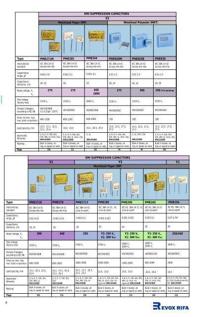
<strong>EMI</strong> SUPPRESSION CAPACITORS<br />
X2<br />
Metallized Paper (MP) Metallized Polyester (MKT)<br />
Bulk in boxes, on<br />
tray or taped on reels<br />
PME271Y<br />
IEC 384-14 Y2<br />
Line-to-earth<br />
PME289<br />
IEC 384-14 Y2, X1<br />
Line-to-earth<br />
0.001-0.1 0.001-0.022<br />
PME290 PME265 PME294<br />
IEC 65, 384-14 Y2, X1<br />
Line-to-earth<br />
IEC 65, 384-14 Y2<br />
Line-to-earth<br />
IEC 65, 384-14 Y1<br />
Line-to-earth<br />
0.001-0.022 0.033-0.1 0.47-4.7nF<br />
20 20 20 20 20<br />
2700 V DC<br />
250 Y2: 250 VAC Y2: 250 VAC Y2: 250 VAC 250/440<br />
X1: 300 VAC X1: 300 VAC X1: 300 VAC<br />
2700 VDC<br />
3000 V DC<br />
2000 V AC<br />
3000 V DC<br />
2000 V AC<br />
4000 V AC<br />
40/100/56/B 40/100/56/C 40/100/56/C 40/085/21/B 40/100/56/C<br />
1000-2000 1400-2000 1400-2000 600-2000 2000<br />
10.2, 15.2, 20.3<br />
22.5, 25.4<br />
S, N, D, FI, VDE, SEV,<br />
ÖVE, IMQ, CSA, UL<br />
EN132400<br />
IEC 384-14 X2<br />
Across-the-line<br />
15.2, 20.3, 25.4<br />
<strong>EMI</strong> SUPPRESSION CAPACITORS<br />
X1 Y2<br />
Metallized Paper (MP)<br />
10.2, 15.2, 20.3,<br />
22.5, 25.4<br />
S, N, D, FI, VDE, SEV,<br />
ÖVE<br />
EN132400<br />
Bulk in boxes, on<br />
tray or taped on reels<br />
10.0, 15.0 10.0, 15.0<br />
20.3, 25.4 15.0<br />
S, N, D, FI, VDE, SEV, ÖVE,<br />
IMQ, UL 1414, CSA +X1<br />
approvals EN132400<br />
Bulk in boxes, on<br />
tray or taped on reels<br />
S, N, D, FI, VDE, SEV, ÖVE,<br />
IMQ, UL 1414 +X1<br />
approvals EN132400<br />
Bulk in boxes, on<br />
tray or taped on reels<br />
S, N, D, FI, VDE, SEV,<br />
ÖVE, UL 1414, CSA,<br />
EN132400<br />
Bulk in boxes, on<br />
tray or taped on reels<br />
S, N, D, FI, VDE, SEV, IMQ,<br />
UL 1414 Double protection,<br />
CSA EN132400<br />
Bulk in boxes, on<br />
tray or taped on reels<br />
Page 106 110 106 114 116 104 118<br />
Y1
Type:<br />
International<br />
standard<br />
Capacitance<br />
range, µF<br />
Capacitance<br />
tolerance, ±%<br />
Rated voltage, V AC<br />
V DC<br />
Test voltage<br />
(factory test)<br />
Climatic Category<br />
according to IEC 68<br />
Pulse rise time, V/µs<br />
max. dU/dt in operation<br />
Lead spacing, mm<br />
Approvals/<br />
Remarks<br />
Packing<br />
Page<br />
Type:<br />
International<br />
standard<br />
Capacitance<br />
range, nF<br />
Capacitance<br />
tolerance, ±%<br />
Rated voltage, V DC<br />
V AC<br />
Climatic Category<br />
according to IEC 68<br />
Pulse rise time, V/µs<br />
Lead spacing, mm<br />
Approvals/<br />
Remarks<br />
Packing<br />
<strong>EMI</strong> SUPPRESSION CAPACITORS<br />
_<br />
0.1-1.0<br />
R:22-680Ω<br />
General Purpose<br />
PME260 PME261<br />
_ _<br />
0.047-2.0<br />
20<br />
R: 30<br />
375 V DC<br />
<strong>EMI</strong> SUPPRESSION CAPACITORS<br />
RC<br />
Metallized Paper (MP)<br />
125<br />
250<br />
Test voltage<br />
(factory test) 375 V DC 800 V DC 1260 VAC 2000 VAC<br />
Page<br />
10<br />
X2+2xY2<br />
PZB300<br />
IEC 384-14<br />
X2+2Y2, Delta<br />
X2: 0.1, 0.15<br />
Y2: 0.0022, 0.0033,<br />
0.0047<br />
20<br />
275<br />
X2: 1800 V DC<br />
Y2: 2700 V DC<br />
40/100/56/B<br />
X2: 600<br />
Y2: 1000<br />
20.0<br />
S, N, D, FI, VDE, SEV, ÖVE,<br />
IMQ, UL,CSA.Option: Faston<br />
connectors EN132400<br />
Bulk in boxes, on<br />
tray or taped on reels<br />
125<br />
250<br />
40/070/56 40/070/56<br />
150-1000 220-2000<br />
10.2, 15.2, 20.3<br />
25.4<br />
Bulk in boxes, on<br />
tray or taped on reels<br />
PMR205<br />
PMR209<br />
IEC 384-14 X2<br />
Across-the-line<br />
20<br />
R: 30<br />
1500 VDC<br />
PMR210<br />
IEC 65, X1<br />
Line-to-earth<br />
3000 V DC<br />
2000 V AC<br />
40/085/56 40/085/56/B 40/085/21/B<br />
15.2, 20.3, 25.4 15.2, 20.3, 25.4<br />
Integrated resistor<br />
Bulk in boxes, on<br />
tray or taped on reels<br />
0.0082<br />
-1.0<br />
0.001<br />
-0.15<br />
0.001<br />
-0.1<br />
10, 5 20, 10 20, 10<br />
220<br />
400<br />
300<br />
630<br />
10.2, 15.2, 20.3<br />
25.4<br />
500<br />
1000<br />
Bulk in boxes, on<br />
tray or taped on reels<br />
0.047-0.47<br />
R:22-470Ω<br />
250<br />
630<br />
S, N, D, FI, VDE, SEV, UL<br />
Integrated resistor<br />
EN132400<br />
Bulk in boxes, on<br />
tray or taped on reels<br />
0.022-0.1<br />
R:100Ω<br />
20<br />
R: 30<br />
250<br />
X1: 300 V AC<br />
15.2, 20.3, 25.4<br />
S, N, D, VDE, SEV, ÖVE,<br />
UL 1414. Integrated<br />
resistor. EN132400<br />
Bulk in boxes, on<br />
tray or taped on reels<br />
PMZ2035<br />
IEC 384-14<br />
0.1-0.15<br />
R:150-330Ω<br />
20<br />
R: 30<br />
1800 V DC<br />
40/085/56/B<br />
25.4<br />
440<br />
S, UL<br />
EN132400<br />
Bulk in boxes or<br />
on tray<br />
122 128 130 132 134<br />
Metallized Paper (MP)<br />
68 70<br />
When the independent<br />
Swiss testing house, Quinel,<br />
performed extensive tests<br />
encompassing much of<br />
EN132400 on 9 capacitor<br />
series from 7 leading<br />
manufacturers, 5 of the 9<br />
capacitor series failed to<br />
pass the test!<br />
Read about the Quinel<br />
test on our website<br />
(http.//www.rifa.se/test).<br />
If you don’t have access to<br />
Internet, call us and we’ll fax<br />
or mail it to you.<br />
9
10<br />
EVOX Type:<br />
International<br />
standard<br />
Capacitance<br />
range, nF<br />
Capacitance<br />
tolerance, ±%<br />
Rated voltage, V DC<br />
V AC<br />
Climatic Category<br />
according to IEC 68<br />
Pulse rise time, V/µs<br />
Lead spacing, mm<br />
Approvals/<br />
Remarks<br />
Packing<br />
Page<br />
Type:<br />
International<br />
standard<br />
Capacitance<br />
range, µF<br />
Capacitance<br />
tolerance, ±%<br />
Rated voltage, V DC<br />
V AC<br />
Climatic Category<br />
according to IEC 68<br />
Pulse rise time, V/µs<br />
Lead spacing, mm<br />
Packing<br />
Page<br />
Metallized (MKP)<br />
PHE425<br />
CECC 31201-001<br />
IEC 384-16<br />
Stab. Class 1<br />
3.3-135<br />
1, 2, 5<br />
PULSE AND HIGH FREQUENCY CAPACITORS<br />
Polypropylene<br />
Metallized Polypropylene (MKP)<br />
Film/Foil (KP)<br />
PMR PHE427<br />
IEC 384-16<br />
Grade 1.1<br />
0.001-12.0<br />
10, 5, 3.5, 2.5, 2<br />
100-630<br />
63-250<br />
55/105/56<br />
20-200<br />
63-400<br />
40-220<br />
5.0, 7.5, 10.0, 15.0,<br />
22.5, 27.5, 37.5<br />
Bulk in boxes<br />
Available taped for<br />
automatic insertion<br />
PRECISION CAPACITORS<br />
Polypropylene<br />
PFR<br />
IEC 384-13<br />
0.1-22.0<br />
10, 5, 2.5, 2, 1<br />
63-1000<br />
40-250<br />
55/085/56 55/100/56<br />
10-40 1000<br />
186 166 176 - -<br />
IEC 384-17<br />
Grade 1.1<br />
PHE428<br />
IEC 384-17<br />
Grade 1.1<br />
0.00068-6.8 0.001-1.0<br />
10, 5, 3.5, 2.5, 2 10, 5, 3.5, 2.5, 2<br />
160-1000<br />
100-375<br />
55/105/56 55/105/56<br />
50-2000 700-2500<br />
7.5, 10.0, 15.0,<br />
22.5, 27.5, 37.5<br />
Bulk in boxes<br />
Available taped for<br />
automatic insertion<br />
630-2000<br />
400-650<br />
15.0, 22.5, 27.5,<br />
37.5<br />
Bulk in boxes<br />
Available taped for<br />
automatic insertion<br />
SFA SFR<br />
DIN 40040<br />
2.73<br />
0.047-100<br />
7.5 5.0 Axial<br />
Axial<br />
MUAHAG<br />
Bulk in boxes<br />
Available taped for<br />
automatic insertion<br />
Bulk in boxes<br />
Available taped for<br />
automatic insertion<br />
PFA<br />
DIN 40040<br />
2.73<br />
0.047-100<br />
20, 10, 5, 2.5, 2,<br />
1 or 1 pF<br />
25-630<br />
10-125<br />
GPE<br />
-40 to +85°C<br />
Bulk in boxes<br />
20, 10, 5, 2.5, 2,<br />
1 or 1 pF<br />
25-630<br />
10-125<br />
JSG<br />
-10 to +70°C<br />
Bulk in boxes<br />
PFR<br />
IEC 384-13<br />
0.0001-0.022<br />
10, 5, 2.5, 2, 1<br />
63-1000<br />
40-250<br />
55/100/56<br />
1000<br />
DIN 40040<br />
2.73<br />
0.1-10.0<br />
20, 10, 5, 2.5, 2,<br />
1<br />
50-160<br />
20-63<br />
JSG<br />
-10 to +70°C<br />
Adjustable<br />
(min. 1 mm)<br />
Bulk in boxes<br />
142 152 160 166 170<br />
5.0<br />
Bulk in boxes<br />
Available taped for<br />
automatic insertion<br />
Polystyrene<br />
Film/Foil (KP) Film/Foil (KS)<br />
CQ92P<br />
IEC 384-13<br />
0.00033-0.1<br />
10, 5, 2<br />
50-250<br />
30-160<br />
40/85/21<br />
3.5, 5.0, 5.5,<br />
7.0, 7.5<br />
Bulk in boxes<br />
Available taped for<br />
automatic insertion
Type:<br />
Capacitance<br />
range, µF<br />
Capacitance<br />
tolerance, ±%<br />
Rated voltage,<br />
U s (V), non repetitive<br />
U RMS (VAC, 50 Hz)<br />
U DC (V)<br />
Climatic Category<br />
according to IEC 68<br />
Pulse rise time, V/µs<br />
Mounting/<br />
terminations<br />
POWER CAPACITORS<br />
Metallized Polypropylene (MKP)<br />
PHG491 PHG495<br />
0.5-10, 0.22-6<br />
0.5-4<br />
5<br />
1500, 2000,<br />
2500<br />
550, 650, 750<br />
1200, 1600, 2000<br />
40/085/56<br />
Screw M6, M8<br />
inner thread<br />
10-25, 9-18, 5-10<br />
10<br />
1500, 2000,<br />
2500<br />
1000, 1350, 1650<br />
40/085/56<br />
Max RMS-current, A 7-80 50-80<br />
Page<br />
Type:<br />
International<br />
standard<br />
Capacitance<br />
range, µF<br />
Capacitance<br />
tolerance, ±%<br />
Rated voltage, V DC<br />
V AC<br />
Climatic Category<br />
according to IEC 68<br />
Pulse rise time, V/µs<br />
Lead spacing, mm<br />
Approvals/<br />
Remarks<br />
Packing<br />
Page<br />
COUPLING/DECOUPLING CAPACITORS<br />
Polyester<br />
Metallized (MKT)<br />
MMK<br />
CECC 30400<br />
IEC 384-2<br />
DIN 44122<br />
20, 10, 5<br />
500-750 25-55<br />
Screw M6, M8<br />
inner thread<br />
192 -<br />
Type:<br />
International<br />
standards<br />
Capacitance<br />
range, µF<br />
Rated voltage, V DC<br />
V AC<br />
Climatic Category<br />
according to IEC 68<br />
Pulse rise time, V/µs<br />
Metallized PET Metallized PEN Metallized PPS<br />
MMC GMC<br />
IEC 384-19<br />
CECC 32200<br />
0.001-10 0.001-10<br />
50-400<br />
30-200<br />
55/100/56<br />
5-50<br />
Taped for automatic<br />
insertion, bulk in<br />
boxes<br />
SMD <strong>Capacitor</strong>s<br />
50-400<br />
30-200<br />
55/125/56<br />
5-50<br />
Taped for automatic<br />
insertion, bulk in<br />
boxes<br />
SMC<br />
IEC 384-20<br />
0.001-0.22<br />
Capacitance<br />
tolerance, % 20, 10 20, 10, 5 10, 5, 2.5, 2<br />
Lead spacing, mm<br />
Approvals/Remarks<br />
Packing<br />
Page<br />
STABLE HIGH TEMPERATURE CAPACITORS<br />
Polycarbonate<br />
Metallized<br />
Metallized (MKC)<br />
MFR CQ92M/SCQ92M CMK CFR<br />
JIS-C-5113<br />
CECC 30500<br />
IEC 384-11<br />
IEC 384-11<br />
IEC 384-6<br />
IEC 384-12<br />
0.001-68 0.001-0.01 0.001-0.47<br />
0.001-10.0<br />
50-1000<br />
30-250<br />
55/100/56<br />
(FME/DIN)<br />
5.0, 7.5, 10.0, 15.0,<br />
22.5, 27.5, 37.5<br />
Bulk in boxes<br />
Available taped for<br />
automatic insertion<br />
20, 10, 5<br />
55/100/56<br />
5.0<br />
100-400<br />
63-220<br />
10, 5<br />
50-250<br />
30-160<br />
3.5, 4.0, 4.5, 5.0,<br />
5.5, 6.5, 7.5, 10.0<br />
20, 10, 5, 2.5<br />
63-400<br />
40-200<br />
55/125/56<br />
(FKD/DIN)<br />
2-60 1000 2-30 1000<br />
CECC 30401-042<br />
Bulk in boxes<br />
Available taped for<br />
automatic insertion<br />
Film/Foil (KT)<br />
-40 to +85°C<br />
Bulk in boxes<br />
Available taped for<br />
automatic insertion<br />
5.0, 7.5, 10.0, 15.0,<br />
22.5, 27.5<br />
CECC 30501-020<br />
Bulk in boxes<br />
Available taped for<br />
automatic insertion<br />
5.7, 7.3, 10.2,<br />
12.7, 16.5<br />
Film/Foil (KC)<br />
0.0001-0.015<br />
10, 5, 2.5<br />
55/125/56<br />
(FKD/DIN)<br />
5.0<br />
100-400<br />
63-200<br />
Bulk in boxes<br />
Available taped for<br />
automatic insertion<br />
5.7, 7.3, 10.2,<br />
12.7, 16.5<br />
SMR<br />
PPS<br />
0.0022-0.47<br />
10, 5, 2.5, 2<br />
55/125/56<br />
(FKD/DIN)<br />
6-15<br />
5.0<br />
50-100<br />
30-63<br />
Polyphenylene sulfide<br />
High temperature<br />
applications<br />
Bulk in boxes<br />
Available taped for<br />
automatic insertion<br />
26 58 60 44 64 54<br />
50-250<br />
30-160<br />
55/125/56<br />
6-20<br />
5.7, 7.3<br />
150°C<br />
application possible<br />
Taped for automatic<br />
insertion, bulk in<br />
boxes<br />
76 82 86<br />
11
General information<br />
Q u a l i t y<br />
<strong>Evox</strong> <strong>Rifa</strong> product quality<br />
The quality of <strong>Evox</strong> <strong>Rifa</strong>’s products and services<br />
is based on a continuous strive<br />
towards excellency throughout the whole<br />
organization. Skilled and motivated personnel,<br />
technical know-how and modern equipment<br />
combined with extensive quality assurance<br />
make <strong>Evox</strong> <strong>Rifa</strong> the supplier of components<br />
of the highest quality.<br />
The up-to date quality tools like Statistical<br />
Process Control (SPC) in various forms,<br />
Failure Mode and Effect Analysis (FMEA),<br />
Accelerated Reliability Testing and Zero<br />
Defect Acceptance concept in final testing<br />
are the corner stones of the every day quality<br />
work. Cross-functional teams are routinely<br />
used in Problem Solving (8D method) with<br />
effective Failure Analysis support.<br />
As visible evidence of our quality, all the<br />
manufacturing units world wide are certified<br />
according to EN ISO 9001 or 9002. In<br />
Europe our manufacturing is also CECC<br />
approved with several qualified product families.<br />
Our world famous <strong>EMI</strong> capacitors carry<br />
all the important safety approval marks for<br />
world wide applications.<br />
Customer in focus<br />
12<br />
The only real measure of our total quality<br />
performance is the acceptance of our customers.<br />
<strong>Evox</strong> <strong>Rifa</strong>’s quality work has always been<br />
focused on the customer. We have actively<br />
made quality agreements with ambitious<br />
goal settings with World-Class Companies –<br />
small and large.<br />
This active quality cooperation has been<br />
most fruitful to <strong>Evox</strong> <strong>Rifa</strong> by bringing in most<br />
modern quality tools, but especially by providing<br />
us with reliable feed back on the performance<br />
quality of our products and services.<br />
The cooperation has not only lead to continuous<br />
improvement of the quality of our products,<br />
but sometimes also helped our customers<br />
to spot some weaknesses in their<br />
designs. A visible sign of these close links<br />
between <strong>Evox</strong> <strong>Rifa</strong> and various customers is<br />
the numerous approvals and the performance<br />
awards addressed to <strong>Evox</strong> <strong>Rifa</strong>.
In-House research and development for tomorrow’s needs<br />
<strong>Evox</strong> <strong>Rifa</strong> has over fifty years accumulated<br />
experience in developing a wide range of<br />
world-class capacitor products. Our leading<br />
position in the market with a wide product<br />
range is based on our deep knowledge of<br />
the materials and ways in which they can be<br />
used in capacitor designs to provide the best<br />
possible solutions.<br />
<strong>Evox</strong> <strong>Rifa</strong> invests substantial human and<br />
financial resources in finding new highly reli-<br />
Simulation examples:<br />
Product specific a t i o n Wa r r a n t y, product liability<br />
All descriptions, drawings and other particulars<br />
(including dimensions, materials and<br />
performance data) given by <strong>Evox</strong> <strong>Rifa</strong> are as<br />
accurate as possible but, being given for<br />
general information, are not binding on <strong>Evox</strong><br />
<strong>Rifa</strong> unless specifically agreed in writing. All<br />
dimensions and materials are, unless otherwise<br />
stated, subject to reasonable variations<br />
resulting from the raw material available or<br />
arising in the ordinary course of manufacture.<br />
Any performance data are based upon<br />
<strong>Evox</strong> <strong>Rifa</strong>’s experience and are such as<br />
<strong>Evox</strong> <strong>Rifa</strong> normally expects to achieve.<br />
able and cost effective solutions for today’s<br />
and tomorrow’s needs. Our R&D department<br />
can simulate most operational conditions<br />
and apply our products to the envisaged<br />
working environment, giving to the customer<br />
optimized capacitors for a particular specification.<br />
The simulation capabilities substantially<br />
shorten the design cycle of capacitors. To<br />
assist in shortening the design cycle of our<br />
Relative temperature increase P-tran and P-diss (W)<br />
Pulsed heat Thermal stability<br />
<strong>Evox</strong> <strong>Rifa</strong> warrants that the goods manufactured<br />
by <strong>Evox</strong> <strong>Rifa</strong> are free from defects in<br />
design, material and workmanship.<br />
<strong>Evox</strong> <strong>Rifa</strong>’s liability under this warranty<br />
shall be limited to replacement or repair free<br />
of charge, at one of <strong>Evox</strong> <strong>Rifa</strong>’s factories<br />
selected by <strong>Evox</strong> <strong>Rifa</strong>, provided that notification<br />
of such failure or defect is given to <strong>Evox</strong><br />
<strong>Rifa</strong> immediately upon the same becoming<br />
apparent and that on <strong>Evox</strong> <strong>Rifa</strong>’s request<br />
and instruction the goods are promptly returned<br />
to <strong>Evox</strong> <strong>Rifa</strong> carriage paid by buyer.<br />
In case the goods thus returned as<br />
defective, prove to be without fault or defect,<br />
<strong>Evox</strong> <strong>Rifa</strong> is entitled to charge buyer 10% of<br />
the value of the returned goods.<br />
If the goods supplied or part thereof are<br />
not manufactured by or branded <strong>Evox</strong> <strong>Rifa</strong>,<br />
<strong>Evox</strong> <strong>Rifa</strong> will only extend to the buyer the<br />
benefit of the warranty granted by the manufacturer<br />
of the goods.<br />
<strong>Evox</strong> <strong>Rifa</strong>’s liability is further limited to a<br />
period of 12 months from the date of shipment<br />
to buyer.<br />
General information<br />
Q u a l i t y<br />
customers, we have brought our R&D<br />
department to our customers by providing<br />
them with a CAD program, which allows<br />
them to select the most suitable capacitors<br />
for their application. Our fully equipped EMC<br />
laboratory is also at the disposal of our customers.<br />
Complete <strong>EMI</strong> filters can be designed<br />
and measured there enabling the customers<br />
to comply with the increasingly stringent<br />
<strong>EMI</strong> legislation throughout the world.<br />
<strong>Evox</strong> <strong>Rifa</strong> shall not be liable for any defect<br />
which is due to accident, fair wear and tear,<br />
negligent use, tampering, improper handling,<br />
improper use, improper operation or improper<br />
storage or any other default on the part<br />
of any person other than <strong>Evox</strong> <strong>Rifa</strong>.<br />
<strong>Evox</strong> <strong>Rifa</strong> shall have no other liabilities in<br />
case of defective goods than those stated<br />
above shall under no circumstances be liable<br />
for any consequential loss or damage arising<br />
from the use of goods sold by <strong>Evox</strong> <strong>Rifa</strong>.<br />
Liability under paragraph 823 BGB is<br />
expressly excluded.<br />
The above limitations of <strong>Evox</strong> <strong>Rifa</strong>’s liability<br />
for defective goods shall apply also with<br />
regard to product liability, and <strong>Evox</strong> <strong>Rifa</strong> shall<br />
have no responsibility for injury to persons or<br />
for damage to goods or property of any kind.<br />
In case of product liability claims from<br />
third parties against <strong>Evox</strong> <strong>Rifa</strong>, not falling<br />
within <strong>Evox</strong> <strong>Rifa</strong>’s liability in accordance with<br />
the above, buyer shall hold <strong>Evox</strong> <strong>Rifa</strong> harmless.<br />
13
General information<br />
Application guide<br />
<strong>Capacitor</strong> selection guide<br />
14<br />
CAPACITOR FUNCTION CRITERIA<br />
BLOCKING AND COUPLING Blocking: High insulation<br />
C provides a high resistance<br />
series impedance for<br />
limiting the low-frequency<br />
AC or DC current.<br />
Coupling: Low dissipation factor<br />
C provides a low Low inductance<br />
series impedance for<br />
transferring AC power<br />
or signal information from<br />
one circuit or system to<br />
another.<br />
BYPASSING C provides a low series Low dissipation factor<br />
impedance AC path Low inductance<br />
around a given circuit High capacitance tolerance<br />
element<br />
FILTERING, FREQUENCY DISCRIMINATION <strong>Capacitor</strong> filter network Precision capacitor stability<br />
Passband:<br />
f L = lower 3 dB frequency<br />
f H = higher 3 dB frequency<br />
designed for the Low dissipation factor<br />
frequency band fL - fH Close capacitance tolerance<br />
TIMING, OSCILLATION A timing element and a capacitor Stability of electrical<br />
are used to introduce time delays. characteristics<br />
Close capacitance tolerances<br />
SMOOTHING AND ENERGY STORAGE C maintains the working Good pulse and AC<br />
voltage of the controlled characteristics<br />
circuit and suppresses Low dissipation factor<br />
transient (high frequency)<br />
voltages. Charge of C enables<br />
(high) energy pulses.<br />
TEMPERATURE COMPENSATION Circuit design utilizes change of Linear temperature coefficient<br />
capacitance with temperature. Stability of electrical values<br />
Positive TC<br />
Negative TC<br />
PULSE COUPLING Coupling/decoupling of high energy, Good pulse and AC characteristics<br />
fast rise pulses. High voltage proof<br />
Zero TC<br />
Low dissipation factor
Typical applications of film capacitors<br />
Peak detector<br />
In this application, C (e.g. 1.0 µF EVOX PMR<br />
or CMK) will charge to the peak value of the<br />
signal to be detected, and hold the voltage<br />
impressed upon it. A polypropylene or polycarbonate<br />
capacitor is recommended. Most<br />
other capacitors do not retain the stored voltage<br />
due to dielectric absorption. The capacitor<br />
acts in the energy storage mode.<br />
Pulse forming circuit<br />
In this application, C ( e.g. 0.01 µF MMK)<br />
charges according to the RC time constant<br />
and determines the output pulse duration. A<br />
polyester capacitor is recommended due to<br />
its stable capacitance values. The capacitor<br />
acts in the timing mode.<br />
Sample and hold circuit<br />
In this application, C (e.g. 1.0 µF EVOX<br />
PMR) retains the stored voltage. PMR is<br />
recommended due to its extremely low dielectric<br />
absorption.<br />
Multivibrator<br />
In this application, C (e.g. PFR, SMR or<br />
CMK) defines the multivibrator frequency f.<br />
CMK (PFR for values < 0.01 µF) is recommended<br />
due to its highly stable electrical<br />
value. The capacitor acts in the timing mode.<br />
Input card filtering in a microprocessor<br />
system<br />
In this application, the high frequency interference<br />
of the microprocessor system input<br />
signal is coupled to the ground by C (e.g. 0.1<br />
µF MMK). A polyester capacitor is recommended<br />
due to its low losses. The capacitor<br />
acts mainly in the bypass mode.<br />
1 MHz FET Crystal Oscillator<br />
In this application, C (e.g. 300 pF PFR) defines<br />
the oscillator frequency. The capacitor<br />
acts in the timing and temperature compensation<br />
modes. PFR is recommended due to<br />
its linear negative temperature coefficient<br />
and highly stable electrical values.<br />
Passive filters<br />
General information<br />
Application guide<br />
In high-pass filter, C 1 forms an RC circuit,<br />
which carries frequencies higher than f L. In a<br />
low-pass filter, C 2 forms an RC circuit, which<br />
carries frequencies lower than f H. In a bandpass<br />
filter, the bandwidth is defined by C 3<br />
and C 4. C 4 acts as a high-pass filter creating<br />
high impedance for low frequencies. C 3<br />
shortcuts high frequencies to the ground.<br />
CMK capacitors are recommended due to<br />
their highly stable electrical values.<br />
Voltage regulator<br />
In this application, C 1 (e.g. 0.01 µF MMK)<br />
p r otects the rectifier diodes by suppressing<br />
high frequency interference transient spikes.<br />
C 2 and C 3 (e.g. 0.1 µF MMK) are required as<br />
transient spike suppressors. C 4 (e.g. 0.047 µF<br />
EVOX PMR) acts as a current source for the<br />
highspeed IC switching spikes. MMK is<br />
recommended due to low inductance (C 1, C 2,<br />
C 3), EVOX PMR due to high insulation resistance<br />
and low losses (C 4) .<br />
Electromagnetic<br />
Interference<br />
<strong>Suppression</strong>.<br />
Please see pages 93-94<br />
<strong>Capacitor</strong>s are typically used in applications where more than one of these basic functions have been combined.<br />
15
General information<br />
Terms and definitions<br />
Terms and defin i t i o n s<br />
Rated capacitance (C R)<br />
The rated capacitance of a capacitor is the<br />
value which is indicated upon it. The capacitance<br />
is measured at 1 kHz and +23°C.<br />
Rated voltage (U R)<br />
The rated voltage is the maximum direct<br />
voltage or the maximum RMS alternating<br />
voltage which may be applied continuously to<br />
the terminals of the capacitor at any temperature<br />
within the rated temperature range.<br />
Rated temperature<br />
The rated temperature is the maximum<br />
ambient temperature at which the rated<br />
voltage can be continuously applied.<br />
Climatic category<br />
The climatic category states the category<br />
temperature range and the humidity class.<br />
For example 40/085/56 stands for – 40°C to<br />
+ 85°C; 56 states that the steady state humidity<br />
test should take 56 days.<br />
Tangent of the loss angle<br />
(Dissipation factor, tanδ)<br />
The tangent of the loss angle is the power<br />
loss of the capacitor divided by the reactive<br />
power of the capacitor at a sinusoidal<br />
voltage of specified frequency. The tangent<br />
of loss angle is given in percent (Eg 0.01<br />
DF=1%).<br />
16<br />
The dissipation factor is of interest especially<br />
when the capacitor is operated on AC. The<br />
dielectric loss causes heating of the capacitor<br />
which under unfavourable circumstances<br />
may lead to a destructive breakdown.<br />
This will not happen if the capacitor is<br />
used within specified limits.<br />
The ability to withstand short duration thermal<br />
and voltage overload is greater for small<br />
capacitors than for large ones.<br />
Insulation resistance<br />
The values given in the catalogue indicate<br />
the insulation resistance after one minute of<br />
electrification at +23°C with the following<br />
voltages: 100 VDC for capacitors rated at<br />
100 to 500 VDC and 500 VDC for capacitors<br />
rated at ≥ 500 VDC. Insulation resistance is<br />
temperature dependent and is approximately<br />
halved for each 7°C of temperature rise.<br />
Multilayer construction provides insulation<br />
resistance higher than that of single-layer<br />
types.<br />
Pulse operation<br />
<strong>Capacitor</strong>s loaded with pulses with fast rise<br />
or fall times (high dU/dt) will be exposed to<br />
high current pulses. In order not to overload<br />
the internal connections the current must be<br />
limited. The current limits for a specific type<br />
are dependent upon:<br />
• Amplitude and form of the pulse<br />
• Rated voltage of the capacitor<br />
• C a p a c i t a n c e<br />
• Geometrical configuration of the winding<br />
dU/dt =U R/(R × C)<br />
UR = Rated voltage<br />
R = Discharge resistor<br />
C = Rated capacitance<br />
At repeated pulse operation, self-heating, ambient<br />
temperature and cooling set the load limit.<br />
Pulse current limits are commonly expressed<br />
in the form of max. permitted dU/dt in volts<br />
per microsecond. The figures stated in the<br />
type specifications refer to an unlimited<br />
number of pulses charging or discharging<br />
from rated voltage U R.<br />
Passive flammability<br />
The ability of a capacitor to burn with a flame<br />
as a consequence of the application of an<br />
external source of heat.<br />
Resonance frequency<br />
The resonance frequency of a capacitor is<br />
reached when<br />
ωL = 1/ωC<br />
ω = 2πf (f=frequency)<br />
L = inductance caused by the<br />
winding and the length of the leads<br />
C = the capacitance at f.
Properties of dielectrics<br />
POLYESTER (PET)<br />
Metallized and Film/foil<br />
High dielectric constant and high dielectric strength provides good<br />
volumetric efficiency for metallized polyester film capacitors.<br />
Metallized polyester film has excellent self-healing properties.<br />
Typical applications: Bypassing, coupling.<br />
POLYESTER (Polyethylene Naphthalate, PEN)<br />
Metallized<br />
High temperature Polyester. Relatively high dielectric constant and<br />
dielectric strength, and availability of thin films, provide good volymeric<br />
efficiency for metallized construction. High melting point allowes<br />
SMD constructions and service in high ambient temperatures.<br />
General purpose capacitor.<br />
POLYPROPYLENE (PP)<br />
Metallized and Film/foil<br />
Very low losses, low dielectric absorption, high dielectric strength,<br />
very high insulation resistance, and negative temperature coefficient.<br />
Typical applications: Stable oscillators and filters. Sample & hold circuits,<br />
pulse handling circuits.<br />
POLYCARBONATE (PC)<br />
Metallized and Film/foil<br />
Very low temperature dependency, wide operating temperature<br />
range, good long term stability, and low losses.Typical applications:<br />
Timers and filters. Applications in high ambient temperatures.<br />
Numerical comparison of film materials<br />
General information<br />
Properties of dielectric materials<br />
POLYSTYRENE (PS)<br />
Film/foil<br />
Extremely low losses, low dielectic absorption, good long term stability,<br />
very high insulation resistance, and a small, negative temperature<br />
coefficient. Typical applications: Timers and filters.<br />
POLYPHENYLENE SULPHIDE (PPS)<br />
Metallized<br />
Low losses, wide operating temperature range, low temperature<br />
coefficient, good stability.<br />
Typical applications: Timers and filters. Automotive and other applications<br />
in high ambient temperatures.<br />
PAPER<br />
Metallized<br />
High dielectric constant. Excellent self-healing properties and transient<br />
handling capability. High ionisation level due to impregnated dielectric<br />
material. Outstanding reliability in mains connected and other<br />
low frequency applications.<br />
Material Min. film Dielectric Operating Temperature Dissipation Insulation Dielectric<br />
(Trade names) thickness constant temperature coefficient factor time absorption<br />
(µm) at 1 kHz, (°C) (ppm/°C) at 1 kHz, constant (s) %<br />
+23°C +23°C at +23°C<br />
Polyester (Mylar, Lumirror, PET 0.9 3.3 –55 ... +100 +400 (±200) 0.5% 25 000 0.2<br />
Hostaphan, Diafoil) (... +125)<br />
Polyethylene PEN 1 3.0 –55 ... +125 +200 (±150) 0.4% 25 000 1.2<br />
Naphthalate (... +150)<br />
Polycarbonate PC 1.5 2.8 –55 ... +125 0 (±100) 0.15% 25 000 0.06<br />
(Capfilm) nonlinear<br />
Polypropylene (Torayfan, PP 4 2.2 –55 ... +85 –200 0.03% 100 000 0.01<br />
Safidep, Trespaphan) (... +105) (–100, +50)<br />
almost linear<br />
Polystyrene PS 4 2.5 –40 ... +70 –150 (±50) 0.02% 100 000 0.01<br />
(Styroflex) (... +85) linear<br />
Polyphenylene sulfide PPS<br />
2 3.0 –55 ... +125 0 (–50) 0.06% 10 000 0.05<br />
(Torelina) (... +150) up to +100<br />
Paper Impregnated 7 5.5 –40 ... +110 +1200 (±200) 0.8% 15 000<br />
17
General information<br />
Properties of dielectrics<br />
<strong>Capacitor</strong> equivalent diagram<br />
18<br />
Dissipation factor vs. temperature Capacitance vs. temperature<br />
Dissipation factor vs. frequency<br />
Insulation resistance vs. temperature<br />
C = nominal value of the capacitor<br />
L = inductance<br />
(leads, metallization, winding)<br />
ESR = equivalent series resistance<br />
(leads, metallization, metal spraying)<br />
IR = insulation resistance<br />
(properties of the dielectric material)<br />
Capacitance vs. frequency<br />
ΔC = variable capacitance<br />
(temperature, DC voltage, frequency<br />
changes)<br />
PR = dielectric polarization resistance<br />
C da = dielectric absorption
R e l i a b i l i t y<br />
The reliability of a capacitor is mainly a function of:<br />
• The construction; dielectric material and its thickness<br />
• The manufacturing process<br />
• The application; electrical stress and temperature<br />
The failure rate, λ, vs. voltage and temperature for the most common<br />
dielectric materials is shown in the diagrams below. U R = rated voltage.<br />
The operating life (L) can be calculated as:<br />
L =<br />
1<br />
× l n<br />
1<br />
λ 1 – F<br />
where F is the expected probability of failures.<br />
– 9<br />
E x a m p l e : I f λ = 20 × 1 0<br />
MTBF (mean time between failures) = 1 / λ<br />
it takes 6 years to have<br />
F = 0.001 (0.1% failures)<br />
and 300 years to have<br />
F = 0.05 (5% failures)<br />
General information<br />
Properties of dielectric materials<br />
19
General information<br />
O r d e r i n g<br />
How to order EVOX capacitors<br />
The <strong>Evox</strong> article code includes all the information needed to specify the<br />
product characteristics and type of packing. Please see the example below.<br />
The first letter of the capacitor type code specifies the dielectric<br />
material: M for polyester (PET), C for polycarbonate, P for polypropylene,<br />
G for polyphenylene naphthalate and S for polyphenylene<br />
sulphide. The second letter indicates the electrode construction:<br />
M for metallized and F for film/foil.<br />
The requested lead spacing is indicated in mm after the third<br />
letter.<br />
The rated capacitance value of the product is indicated with three<br />
digits (four digits for some special capacitance values). The two<br />
first digits indicate the two most significant digits of the capacitance<br />
value, and the third digit gives the number of following zeroes. This<br />
gives the capacitance value expressed in picofarads.<br />
Examples:<br />
103 = 10000 pF = 10 nF = 0.01 µF<br />
104 = 100000 pF = 100 nF = 0.1 µF<br />
106 =10000000 pF = 10000 nF = 10 µF<br />
When three significant digits are needed to express the capacitance<br />
value, a four digit long code is used. Again, the last digit gives the<br />
amount of numbers after the two most significant digits. However,<br />
instead of adding just zeroes, the first number to be added is the<br />
third significant number.<br />
20<br />
Examples:<br />
4582 =4580 pF = 4.58 nF =0.00458 µF<br />
1464 =146000 pF = 146 nF =0.146 µF<br />
The capacitance tolerance is expressed with letter codes:<br />
M ± 20 % J ± 5 %<br />
V 0 to +20 % X ± 3.5 %<br />
P 0 to +10 % H ± 2.5 %<br />
L 0 to -10 % G ± 2 %<br />
K ± 10 % F ± 1 %<br />
The rated voltage of a capacitor is expressed with numbers<br />
specifying the voltage in DC volts.<br />
Lead length is expressed in mm, following the letter L. Standard<br />
+1.0<br />
lead length is 4.0 - 0<br />
mm. Other lead lengths are available on<br />
request.<br />
Packing of the capacitors is specified by the packing code:<br />
BULK loose capacitors in boxes<br />
TRAY capacitors with 22.5, 27.5 and 37.5 mm pitch on a tray<br />
TR16 capacitors taped and reeled with H = 16.5 mm<br />
TR18 capacitors taped and reeled with H = 18.5 mm<br />
TA16 capacitors taped in ammo pack with H = 16.5 mm<br />
TA18 capacitors taped in ammo pack with H = 18.5 mm
How to order RIFA <strong>Capacitor</strong>s<br />
The <strong>Rifa</strong> article code includes all the information needed to specify the<br />
product characteristics and type of packing. Please see the example below.<br />
The article code consists of a maximum 20 positions divided in two<br />
blocks. The first 13 positions form the first block, which is given in<br />
each article table. There are a few exceptions to this system.<br />
The six first digits specify the capacitor type.<br />
The rated voltage in DC is expressed with a letter, being the<br />
seventh digit in the article code:<br />
C 63 K 400<br />
D 100 M 630<br />
F 160 P 1000<br />
H 250 R 1600<br />
S 2000<br />
The lead spacing in mm is specified with a letter in the eighth digit:<br />
K 7.5 D 22.5<br />
A 10 E 25.4<br />
B 15 F 27.5<br />
C 20.3 R 37.5<br />
The rated capacitance is expressed in four digits, where the first<br />
digit is the number of digits in the capacitance value in pF, and the<br />
next three digits are the three significant digits in the capacitance<br />
value.<br />
Examples:<br />
6100 = 100000 pF = 0.1 µF<br />
4625 = 6250 pF = 0.00625 µF<br />
The capacitance tolerance is expressed with letter codes:<br />
M ± 20 % F ± 1 %<br />
K ± 10 % P ± 0.625 %<br />
J ± 5 % D ± 0.5 %<br />
X ± 3.5 % V ± 5 pF<br />
H ± 2.5 % A ± 1.5 pF<br />
G ± 2 % Y ± 1 pF<br />
R ± 1.25 %<br />
The manufacturing code Y Z, according to IEC 62<br />
where Y = year, Z = month.<br />
General Information<br />
O r d e r i n g<br />
The second block, i.e.the digits 14 to 20, describes the options for<br />
each article, such as lead length, taping or insulated leads. Please<br />
see the Ordering Information for each article.<br />
Year Code Year Code Year Code Month Code Month Code<br />
1983 R 1990 A 1997 J Jan 1 July 7<br />
1984 S 1991 B 1998 K Febr 2 Aug 8<br />
1985 T 1992 C 1999 L March 3 Sept 9<br />
1986 U 1993 D 2000 M April 4 Oct O<br />
1987 V 1994 E 2001 N May 5 Nov N<br />
1988 W 1995 F 2002 P June 6 Dec D<br />
1989 X 1996 H 2003 R<br />
21
General Information<br />
Ta p i n g<br />
Taping of <strong>Evox</strong> <strong>Rifa</strong> capacitors<br />
The taping is carried out in<br />
accordance with IEC 286-2.<br />
Taping specification<br />
Dimensions in mm IEC 286-2<br />
Lead spacing F + 0.6 5.0/7.5 – 0.1<br />
+ 0.6 7.5 – 0.1<br />
Crimped leads 4)<br />
+ 0.6 10.0/15.0/ * – 0.1<br />
+ 0.6 10.2/15.2/20.3 – 0.1<br />
+ 0.6 F – 0.1<br />
Carrier tape width W 18 ± 0.5 18 ± 0.5 18 ± 0.5 18 ± 0.5 18 – 0.5<br />
Hold-down tape width W0 9 ± 0.3 12 ± 0.3 12 ± 0.3 12 ± 0.3<br />
Position of sprocket hole W 1 9 ± 0.5 9 ± 0.5 9 ± 0.5 9 ± 0.5 9 – 0.5<br />
Distance between tapes W 2 3 max 3 max 3 max 3 max 3 max<br />
Sprocket hole diameter D 0 4 ± 0.2 4 ± 0.2 4 ± 0.2 4 ± 0.2 4 ± 0.2<br />
Feed hole pitch P 0 1) 12.7 ± 0.3 15 ± 0.3 12.7 ± 0.3 12.7 ± 0.3 12.7 ± 0.3<br />
Distance lead – feed hole P 1 3.85/3.75 ❖ ± 0.7 3.75 ± 0.7 7.7/5.2/7.8 ± 0.7 7.6/5.1/8.9 ± 0.7 P 1 ± 0.7<br />
Max deviation tape – plane Δp 1.3 max 1.3 max 1.3 max 1.3 max 1.3 max<br />
Max lateral deviation Δh 2 max 2 max 2 max 2 max 2 max<br />
Total thickness t 0.7 ± 0.2 0.7 ± 0.2 0.7 ± 0.2 0.7 ± 0.2 0.9 max<br />
Sprocket hole/cap body H 2) 18.5 ± 0.5 18.5 ± 0.5 + 2 18.0 – 0<br />
+ 2 18.0 – 0<br />
16.5 ± 0.5 16.5 ± 0.5<br />
22<br />
+ 2 18.0 – 0<br />
Sprocket hole/crimped leads H 0 2) 16 ± 0.5 16 ± 0.5<br />
18 ± 0.5<br />
Sprocket hole/top of cap body H 1 3) 32/31 max 40 max 43 max 35 max 58 max<br />
1) Cumulative pitch error<br />
2) Alternatives for different insertion machines<br />
3) Depending on case size<br />
4) CQ/SCQ with crimped leads are taped like this with the following exceptions: P1 = 3.85 and W = 18 – 0.5<br />
*) On request 22.5 mm<br />
+ 1.0<br />
+ 1.0<br />
+ 0.75
Taping of <strong>Evox</strong> <strong>Rifa</strong> capacitors, continued<br />
Reel specification<br />
Reel dimensions in mm Tol.<br />
Reel diameter A 360/500 max<br />
Hub diameter N 80 min<br />
Arbor hole C 30 ± 1<br />
Total reel width<br />
measured at hub W2 58 max<br />
Quantity/reel in this catalogue is for 360 mm reel.<br />
The quantity in 500 mm reel is 2x the given quantity.<br />
Ammo pack specification<br />
Ammo pack dimensions in mm<br />
Height H 330 (135 or 200 for CQ/SCQ depending<br />
on capacitance value)<br />
Width W 330 (335 for CQ/SCQ)<br />
Thickness T 50<br />
Ordering codes<br />
The following codes specify the taping options<br />
RIFA T0 Reel with A = 360 mm<br />
T1 A = 500 mm<br />
X2 Reel with A = 360 mm, crimped leads, F = 7.5<br />
(Crimped leads; from 10/10.2/15 to 7.5 mm)<br />
EVOX TR16 Reel with A = 360 mm and H = 16.5 mm<br />
TR18 A = 360 mm and H = 18.5 mm<br />
XR18 A = 360 mm, H = 18.5, F = 7.5, P 0 = 15<br />
TA16 Ammo with H = 16.5 mm<br />
TA18 H = 18.5 mm<br />
How to use these codes:<br />
See general ordering information and information for each article.<br />
Taping of SMD <strong>Capacitor</strong>s; see page 75.<br />
General Information<br />
Taping, continued<br />
23