TPS-6L - Crestron
TPS-6L - Crestron
TPS-6L - Crestron
- TAGS
- crestron
- www.crestron.com

Create successful ePaper yourself
Turn your PDF publications into a flip-book with our unique Google optimized e-Paper software.
<strong>Crestron</strong> <strong>TPS</strong>-<strong>6L</strong><br />
Isys ® 5.7” Wall Mount Touchpanel<br />
Operations & Installation Guide
This document was prepared and written by the Technical Documentation department at:<br />
<strong>Crestron</strong> Electronics, Inc.<br />
15 Volvo Drive<br />
Rockleigh, NJ 07647<br />
1-888-CRESTRON<br />
All brand names, product names and trademarks are the property of their respective owners.<br />
©2008 <strong>Crestron</strong> Electronics, Inc.
<strong>Crestron</strong> <strong>TPS</strong>-<strong>6L</strong> Isys ® 5.7” Wall Mount Touchpanel<br />
Contents<br />
Isys ® 5.7” Wall Mount Touchpanel: <strong>TPS</strong>-<strong>6L</strong> 1<br />
Introduction ..........................................................................................................1<br />
Features and Functions...........................................................................1<br />
Applications ...........................................................................................3<br />
Internal Block Diagram..........................................................................4<br />
Specifications.........................................................................................4<br />
Physical Description...............................................................................7<br />
Industry Compliance ............................................................................11<br />
Setup...................................................................................................................12<br />
Network Wiring ...................................................................................12<br />
Identity Code........................................................................................12<br />
Configuring the Touchpanel.................................................................13<br />
Mounting Options ................................................................................29<br />
Touchpanel Mounting ..........................................................................30<br />
Touchpanel Removal ...........................................................................34<br />
Hardware Hookup ................................................................................34<br />
Recommended Cleaning ......................................................................35<br />
Programming Software.......................................................................................36<br />
Earliest Version Software Requirements for the PC ............................36<br />
Programming with <strong>Crestron</strong> SystemBuilder ........................................36<br />
Programming with D3 Pro ...................................................................36<br />
Programming with SIMPL Windows...................................................36<br />
Programming with VisionTools Pro-e .................................................39<br />
Example Program.................................................................................42<br />
Uploading and Upgrading ..................................................................................43<br />
Establishing Communication ...............................................................43<br />
Programs, Projects and Firmware ........................................................44<br />
Program Checks ...................................................................................44<br />
Problem Solving.................................................................................................45<br />
Troubleshooting ...................................................................................45<br />
Check Network Wiring ........................................................................46<br />
Reference Documents ..........................................................................47<br />
Further Inquiries...................................................................................47<br />
Future Updates .....................................................................................47<br />
Software License Agreement..............................................................................48<br />
Return and Warranty Policies.............................................................................50<br />
Merchandise Returns / Repair Service .................................................50<br />
CRESTRON Limited Warranty ...........................................................50<br />
Operations & Installation Guide – DOC. 6630A Contents • i
<strong>Crestron</strong> <strong>TPS</strong>-<strong>6L</strong> Isys ® 5.7-Inch Wall Mount Touchpanel<br />
Isys ® 5.7” Wall Mount<br />
Touchpanel: <strong>TPS</strong>-<strong>6L</strong><br />
Introduction<br />
Features and Functions<br />
This guide describes multiple models; differences are noted where applicable.<br />
• 5.7" active matrix color touchscreen display<br />
• 16-bit Isys ® graphics | 640 x 480 resolution<br />
• Synapse image rendering algorithm<br />
• Single full motion, fully scalable video window<br />
• Amplified speaker (optional) and microphone<br />
• Includes faceplate with 12 “hard key” pushbuttons<br />
• Button engraving available as solid or backlit text<br />
• No-button blank faceplate also provided<br />
• WAV file audio feedback<br />
• Built-in light sensor<br />
• <strong>Crestron</strong> Home ® CAT5 AV connectivity<br />
• High speed Ethernet and Cresnet ® communications<br />
• Wall, lectern and rack mounting options<br />
• Available in almond, black or white<br />
The Isys ® <strong>TPS</strong>-<strong>6L</strong> Wall Mount Touchpanel delivers high end style and performance<br />
in a compact, cost effective flush mount design. Featuring a bright, beautiful, highcontrast<br />
5.7" color touchscreen with 16-bit Isys graphics, 640 x 480 resolution and<br />
single video window display, the <strong>TPS</strong>-<strong>6L</strong> delivers a world of control capability yet<br />
leaves a very small footprint. The addition of 12 optional pushbuttons provides quick<br />
access to commonly used functions.<br />
<strong>Crestron</strong> ® touchpanels offer an ideal user interface for controlling everything from<br />
basic audio distribution and lighting to complete home automation and multimedia<br />
presentation, providing a wide open canvas for the creation of custom control screens<br />
perfectly tailored to the needs of the end user. Touchpanels do away with piles of<br />
remote controls, cryptic front panels and cluttered wall switches, affording true "one<br />
touch" control over a broad range of complex devices and systems.<br />
Operations & Installation Guide – DOC. 6630A Isys ® 5.7” Wall Mount Touchpanel: <strong>TPS</strong>-<strong>6L</strong> • 1
Isys ® 5.7” Wall Mount Touchpanel <strong>Crestron</strong> <strong>TPS</strong>-<strong>6L</strong><br />
Isys ®<br />
Isys power and beauty are infused throughout <strong>Crestron</strong>’s entire touchpanel lineup.<br />
Under the hood, the Isys engine combines a 32-bit Freescale ColdFire ®<br />
microprocessor with an ingenious and ultra efficient operating system to produce<br />
astonishing full color graphics and high res images with lightning fast performance.<br />
Capabilities include dynamic graphics and text, full motion animations, multimode<br />
objects and PNG translucency.<br />
Synapse <br />
<strong>Crestron</strong>’s exclusive Synapse Image Rendering Algorithm enables system<br />
programmers to produce amazing graphics - faster and easier. Advanced antialiasing<br />
delivers crisper, sharper objects and text. Enhanced 3D effects add new depth and<br />
style. And because Synapse is native to the touchpanel, memory requirements and<br />
upload time are substantially reduced.<br />
Full Motion Video<br />
The <strong>TPS</strong>-<strong>6L</strong> can display full motion video from an external source, providing an<br />
exceptional utility for viewing security cameras and other video signals on the<br />
touchscreen display. The video image is fully scalable for viewing in any sized<br />
window or full screen. The choice of balanced or unbalanced composite inputs<br />
allows compatibility with both conventional coaxial and <strong>Crestron</strong> Home ® Balanced<br />
AV distribution systems.<br />
Audio Features<br />
Customized WAV audio files can be loaded on the touchpanel to add dimension to<br />
its touchscreen graphics using personalized sounds, button feedback and voice<br />
prompts. An external speaker option can be added for amplification of external AV<br />
sources and to support programmable intercom functionality in combination with the<br />
built-in microphone.<br />
<strong>Crestron</strong> Home ® CAT5 AV<br />
The <strong>TPS</strong>-<strong>6L</strong> is ideal for use with AV distribution and intercom systems of all sizes.<br />
Its balanced audio and video connections make installation easy and affordable using<br />
inexpensive CAT5 type wire and <strong>Crestron</strong>'s popular CH CAT5 Balanced AV<br />
distribution switchers. A single balanced video input accepts signals from composite<br />
video sources over wiring distances of up to 750 feet, while balanced audio<br />
connections are included to accept incoming stereo program audio and intercom<br />
signals and to output audio from the internal microphone. Connection to<br />
conventional coaxial video and audio systems is also supported.<br />
Pushbutton Options<br />
The <strong>TPS</strong>-<strong>6L</strong> features a faceplate (bezel) containing 12 programmable “hard key”<br />
pushbuttons, elegantly trimmed by illuminated button dividers. Integral to the<br />
faceplate, the pushbuttons are positioned along the left and right edges of the<br />
touchscreen, making it possible to align dynamically changing text and graphics on<br />
screen beside the pushbuttons to support context sensitive menu functions such as<br />
digital media titles, channels or lighting presets. Custom engraving of the buttons is<br />
available, with a choice of solid or backlit text. A plain, no-button faceplate is also<br />
included, allowing a very clean appearance with no pushbuttons.<br />
2 • Isys ® 5.7” Wall Mount Touchpanel: <strong>TPS</strong>-<strong>6L</strong> Operations & Installation Guide - DOC. 6630A
<strong>Crestron</strong> <strong>TPS</strong>-<strong>6L</strong> Isys ® 5.7” Wall Mount Touchpanel<br />
Light Sensor<br />
A light sensor is built into the <strong>TPS</strong>-<strong>6L</strong> to automatically adjust the display brightness<br />
for optimal visibility under varying light conditions.<br />
High Speed Connectivity<br />
Both Cresnet ® and high speed Ethernet are standard on the <strong>TPS</strong>-<strong>6L</strong>, providing for<br />
easy network integration and seamless communications with <strong>Crestron</strong> control<br />
systems.<br />
Versatile Flush Mount Design<br />
The <strong>TPS</strong>-<strong>6L</strong> is designed for easy flush mount installation in a wall, lectern or similar<br />
flat surface. Mounting clips furnished with the <strong>TPS</strong>-<strong>6L</strong> facilitate a clean installation<br />
in drywall and many furniture applications. Additional mounting options are<br />
available separately including optional back box and 19” rack mount kit.<br />
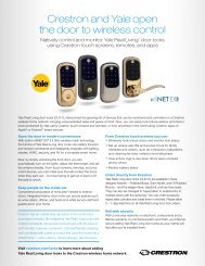
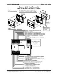
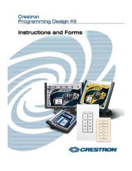
Applications<br />
The following diagram shows a <strong>TPS</strong>-<strong>6L</strong> in a basic AV application.<br />
<strong>TPS</strong>-<strong>6L</strong> Application Diagram<br />
Operations & Installation Guide – DOC. 6630A Isys ® 5.7” Wall Mount Touchpanel: <strong>TPS</strong>-<strong>6L</strong> • 3
Isys ® 5.7” Wall Mount Touchpanel <strong>Crestron</strong> <strong>TPS</strong>-<strong>6L</strong><br />
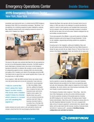
Internal Block Diagram<br />
The following diagram represents the basic operation of the <strong>TPS</strong>-<strong>6L</strong>.<br />
<strong>TPS</strong>-<strong>6L</strong> Internal Block Diagram<br />
Specifications<br />
Specifications for the <strong>TPS</strong>-<strong>6L</strong> are listed in the following table.<br />
<strong>TPS</strong>-<strong>6L</strong> Specifications<br />
SPECIFICATION DETAILS<br />
Touchscreen Display<br />
Display Type TFT Active matrix color LCD<br />
Size 5.7 inch (14.48 cm) diagonal<br />
Aspect Ratio 4:3 VGA<br />
Resolution 640 x 480 pixels<br />
Brightness 400 nits<br />
Contrast 400:1<br />
Color Depth 18-bit, 256 k colors<br />
Illumination Backlit fluorescent<br />
(Continued on following page)<br />
4 • Isys ® 5.7” Wall Mount Touchpanel: <strong>TPS</strong>-<strong>6L</strong> Operations & Installation Guide - DOC. 6630A
<strong>Crestron</strong> <strong>TPS</strong>-<strong>6L</strong> Isys ® 5.7” Wall Mount Touchpanel<br />
<strong>TPS</strong>-<strong>6L</strong> Specifications (Continued)<br />
SPECIFICATION DETAILS<br />
Touchscreen Display (Continued)<br />
Viewing Angle ±80º horizontal, +80º/-70º vertical<br />
Touchscreen Resistive membrane<br />
Processor<br />
CPU 32-bit Freescale ColdFire ® Microprocessor<br />
Memory<br />
SDRAM 32 MB<br />
Flash 32 MB<br />
Maximum Project Size 28 MB<br />
Graphic Engine Isys engine; 16-bit non-palette graphics;<br />
65536 colors; Synapse image rendering<br />
algorithm; multi-mode objects; dynamic<br />
graphics 1 ; PNG translucency, full motion<br />
(60 fps) animation; color key video windowing<br />
Ethernet 10BaseT/100BaseTX, auto switching,<br />
auto-negotiating, autodiscovery, full/half<br />
duplex, TCP/IP, UDP/IP, CIP, DHCP, IEEE<br />
802.3U compliant<br />
Video<br />
Audio<br />
Signal Types Composite<br />
Formats NTSC 480i or PAL 576i<br />
Color Depth 18-bit, 262,144 colors<br />
Windowing Single window, deinterlaced and scalable up<br />
to full screen<br />
Hardware Features Built-in microphone, internal speaker for<br />
WAV/keyclick, optional amplified speaker for<br />
program/intercom, internal volume & tone<br />
control<br />
Audio Feedback (WAV) 8-bit, PCM, mono, 8 kHz sampling rate<br />
Amplification 0.75 Watt for internal WAV/keyclick speaker,<br />
6 Watts for optional program/intercom<br />
speaker (requires SPK-<strong>6L</strong> speaker kit, sold<br />
separately)<br />
Power Requirements<br />
Cresnet Power Usage 15 Watts (0.625 Amp @ 24 Volts DC)<br />
Default Net ID 03<br />
Minimum 2-Series Control<br />
2, 3<br />
System Update File<br />
Environmental<br />
Version 3.137 or later<br />
Temperature 32º to 104ºF (0º to 40ºC)<br />
Humidity 10% to 90% RH (non-condensing)<br />
Heat Dissipation 51 BTU/Hr<br />
(Continued on following page)<br />
Operations & Installation Guide – DOC. 6630A Isys ® 5.7” Wall Mount Touchpanel: <strong>TPS</strong>-<strong>6L</strong> • 5
Isys ® 5.7” Wall Mount Touchpanel <strong>Crestron</strong> <strong>TPS</strong>-<strong>6L</strong><br />
<strong>TPS</strong>-<strong>6L</strong> Specifications (Continued)<br />
Enclosure<br />
SPECIFICATION DETAILS<br />
Construction Injection molded plastic, flush mountable<br />
using (4) clips provided (additional mounting<br />
kits available)<br />
Faceplate Injection molded plastic, button and no-button<br />
faceplates included, optional solid or backlit<br />
engraving sold separately<br />
Dimensions<br />
Height 5.60 in (14.23 cm)<br />
Width 7.40 in (18.80 cm)<br />
Depth 2.28 in (5.78 cm)<br />
3.58 in (9.08 cm) with SPK-<strong>6L</strong> speaker kit<br />
(sold separately)<br />
Weight 1.52 lbs (0.69 kg)<br />
Available Models<br />
<strong>TPS</strong>-<strong>6L</strong>A-T Isys 5.7” Wall Mount Touchpanel, Almond,<br />
Textured<br />
<strong>TPS</strong>-<strong>6L</strong>B-T Isys 5.7” Wall Mount Touchpanel, Black,<br />
Textured<br />
<strong>TPS</strong>-<strong>6L</strong>W-T Isys 5.7” Wall Mount Touchpanel, White,<br />
Textured<br />
Included Accessories<br />
<strong>TPS</strong>-<strong>6L</strong>-FP(A,B,W)-T Button Faceplate w/o Engraving<br />
(specify color)<br />
<strong>TPS</strong>-<strong>6L</strong>-FP(A,B,W)-T-NB No-Button Faceplate w/o Engraving (specify<br />
color)<br />
Available Accessories<br />
SPK-<strong>6L</strong> Speaker Kit<br />
<strong>TPS</strong>-<strong>6L</strong>-FP(A,B,W)-T Button Faceplate w/Custom Engraving<br />
(specify color)<br />
<strong>TPS</strong>-<strong>6L</strong>-FP-BKLT-(A,B,W)-T Backlit Button Faceplate w/Custom Engraving<br />
(specify color)<br />
<strong>TPS</strong>-<strong>6L</strong>-FP(A,B,W)-T-NB No-Button Faceplate w/Custom Engraving<br />
(specify color)<br />
BB-<strong>6L</strong> Pre-Construction Wall Mount Back Box<br />
PMK-<strong>6L</strong> Pre-Construction Wall Mount Kit<br />
TMK-<strong>6L</strong> Trim Ring<br />
MMK-<strong>6L</strong> Mud Ring<br />
WMKT-<strong>6L</strong> Lectern or Post-Construction Wall Mount Kit<br />
with Trim Ring<br />
WMKM-<strong>6L</strong> Post-Construction Wall Mount Kit<br />
with Mud Ring<br />
WMKB-<strong>6L</strong> Replacement Wall Mount Clips<br />
RMK-<strong>6L</strong> Rack Mount Kit<br />
CresCAT ® D <strong>Crestron</strong> Home CAT5 Balanced AV Cable<br />
1. The panel will not load dynamic graphics if they are located on a password protected HTTP server.<br />
2. The latest software versions can be obtained from the <strong>Crestron</strong> website. Refer to the NOTE following<br />
these footnotes.<br />
6 • Isys ® 5.7” Wall Mount Touchpanel: <strong>TPS</strong>-<strong>6L</strong> Operations & Installation Guide - DOC. 6630A
<strong>Crestron</strong> <strong>TPS</strong>-<strong>6L</strong> Isys ® 5.7” Wall Mount Touchpanel<br />
3. <strong>Crestron</strong> 2-Series control systems include the AV2 and PRO2. Consult the latest <strong>Crestron</strong> Product<br />
Catalog for a complete list of 2-Series control systems.<br />
NOTE: <strong>Crestron</strong> software and any files on the website are for Authorized <strong>Crestron</strong><br />
dealers and <strong>Crestron</strong> Authorized Independent Programmers (CAIP) only. New users<br />
may be required to register to obtain access to certain areas of the site (including the<br />
FTP site).<br />
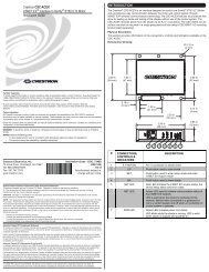
Physical Description<br />
This section provides information on the connections, controls and indicators<br />
available on your <strong>TPS</strong>-<strong>6L</strong>.<br />
<strong>TPS</strong>-<strong>6L</strong> Physical View (with Button Bezel)<br />
Operations & Installation Guide – DOC. 6630A Isys ® 5.7” Wall Mount Touchpanel: <strong>TPS</strong>-<strong>6L</strong> • 7
Isys ® 5.7” Wall Mount Touchpanel <strong>Crestron</strong> <strong>TPS</strong>-<strong>6L</strong><br />
<strong>TPS</strong>-<strong>6L</strong> Dimensions – Front and Side View with Cutaway Showing Internal Controls<br />
<strong>TPS</strong>-<strong>6L</strong> Dimensions and Connections – Rear View<br />
8 • Isys ® 5.7” Wall Mount Touchpanel: <strong>TPS</strong>-<strong>6L</strong> Operations & Installation Guide - DOC. 6630A
<strong>Crestron</strong> <strong>TPS</strong>-<strong>6L</strong> Isys ® 5.7” Wall Mount Touchpanel<br />
Connectors, Controls & Indicators<br />
# CONNECTORS 1 ,<br />
CONTROLS &<br />
INDICATORS<br />
DESCRIPTION<br />
1 BUTTONS (12) Optional engravable pushbuttons with<br />
available backlighting. A non-pushbutton<br />
bezel is also provided if the buttons are not<br />
desired. Refer to “Pushbutton Options” on<br />
page 2 for additional details.<br />
2 MICROPHONE (1) Built-in microphone behind the bezel<br />
supports programmable intercom<br />
functionality.<br />
3 LIGHT SENSOR Programmable photosensor for automatic<br />
backlight dimming. Refer to “Auto Brightness<br />
Control” on page 25 for additional information.<br />
4 RESET BUTTON 2 (1) Miniature pushbutton behind faceplate,<br />
used to reset the touchpanel.<br />
5 LAN<br />
PIN 1<br />
YELLOW<br />
LED<br />
6 NET<br />
PIN 8<br />
GREEN<br />
LED<br />
7 MIC OUT<br />
8 AUDIO INPUT<br />
(Continued on following page)<br />
(1) 8-wire RJ-45 with two LED indicators;<br />
10BaseT/100BaseTX Ethernet port;<br />
Green LED indicates link status;<br />
Yellow LED indicates Ethernet activity<br />
PIN SIGNAL PIN SIGNAL<br />
1 TX + 5 N/C<br />
2 TX - 6 RC -<br />
3 RC+ 7 N/C<br />
4 N/C 8 N/C<br />
(1) Four-position terminal block connector for<br />
data and power. Connects to Cresnet control<br />
network.<br />
Pin 1 (24) Power<br />
Pin 2 (Y) Data<br />
Pin 3 (Z) Data<br />
Pin 4 (G) Ground<br />
(1) 3-pin 3.5mm detachable terminal block;<br />
Balanced mono line level output;<br />
Output impedance: 600 Ω balanced,<br />
300 Ω unbalanced;<br />
Maximum output level: 2 Vrms balanced,<br />
1 Vrms unbalanced<br />
(1) 5-pin 3.5mm detachable terminal block;<br />
Balanced/unbalanced stereo (summed to<br />
mono) line level input (requires SPK-<strong>6L</strong><br />
speaker kit, sold separately);<br />
Input impedance: 10 kΩ balanced,<br />
5 kΩ unbalanced;<br />
Maximum input level: 2 Vrms<br />
balanced/unbalanced;<br />
Normally connects to a <strong>Crestron</strong> CAT5<br />
balanced audio source via CresCAT cable 3 ;<br />
Maximum CAT5 cable length: 1000 feet<br />
Operations & Installation Guide – DOC. 6630A Isys ® 5.7” Wall Mount Touchpanel: <strong>TPS</strong>-<strong>6L</strong> • 9
Isys ® 5.7” Wall Mount Touchpanel <strong>Crestron</strong> <strong>TPS</strong>-<strong>6L</strong><br />
Connectors, Controls & Indicators (Continued)<br />
# CONNECTORS 1 ,<br />
CONTROLS &<br />
INDICATORS<br />
9 NTSC/PAL<br />
INPUT<br />
10 SPEAKER OPTION<br />
DESCRIPTION<br />
(1) 5-pin 3.5mm detachable terminal block;<br />
Balanced (CAT5) or unbalanced (coaxial)<br />
composite video inputs;<br />
Formats: NTSC 480i or PAL 576i;<br />
Input impedance: 100 Ω balanced,<br />
75 Ω unbalanced;<br />
Input level: 1 Vp-p nominal;<br />
Balanced input normally connects to a<br />
<strong>Crestron</strong> CAT5 balanced video source via<br />
CresCAT cable 3 ;<br />
Maximum CAT5 cable length: 750 feet<br />
(1) Six-pin (2x3) rectangular connector;<br />
Connects to optional SPK-<strong>6L</strong> speaker kit<br />
(sold separately).<br />
1. Interface connectors for NET, MIC OUT, AUDIO INPUT, and NTSC/PAL INPUT ports are<br />
provided with the unit.<br />
2. To access the reset button, remove the bezel and then use a narrow blunt instrument such as the end of<br />
a ballpoint pen to press the button.<br />
3. For details on CAT5 wiring, refer to the latest version of the CAT5 Reference Guide (Doc. 6137),<br />
which is available for download from the <strong>Crestron</strong> website (www.crestron.com/manuals).<br />
CAUTION: Do not attempt to press the reset button by inserting a paperclip or<br />
similar device through the small hole in the bezel. This could cause physical damage<br />
to the microphone or the light sensor, or a short circuit on the printed circuit board<br />
located in that area. Remove bezel to access the reset button.<br />
10 • Isys ® 5.7” Wall Mount Touchpanel: <strong>TPS</strong>-<strong>6L</strong> Operations & Installation Guide - DOC. 6630A
<strong>Crestron</strong> <strong>TPS</strong>-<strong>6L</strong> Isys ® 5.7” Wall Mount Touchpanel<br />
Industry Compliance<br />
As of the date of manufacture, the <strong>TPS</strong>-<strong>6L</strong> has been tested and found to comply with<br />
specifications for CE marking and standards per EMC and Radiocommunications<br />
Compliance Labelling.<br />
NOTE: This device complies with part 15 of the FCC rules. Operation is subject to<br />
the following two conditions: (1) this device may not cause harmful interference and<br />
(2) this device must accept any interference received, including interference that may<br />
cause undesired operation.<br />
This equipment has been tested and found to comply with the limits for a Class B<br />
digital device, pursuant to part 15 of the FCC Rules. These limits are designed to<br />
provide reasonable protection against harmful interference in a residential<br />
installation. This equipment generates, uses and can radiate radio frequency energy<br />
and if not installed and used in accordance with the instructions, may cause harmful<br />
interference to radio communications. However, there is no guarantee that<br />
interference will not occur in a particular installation. If this equipment does cause<br />
harmful interference to radio or television reception, which can be determined by<br />
turning the equipment off and on, the user is encouraged to try to correct the<br />
interference by one or more of the following measures:<br />
� Reorient or relocate the receiving antenna.<br />
� Increase the separation between the equipment and receiver.<br />
� Connect the equipment into an outlet on a circuit different from that to<br />
which the receiver is connected.<br />
� Consult the dealer or an experienced radio/TV technician for help.<br />
Operations & Installation Guide – DOC. 6630A Isys ® 5.7” Wall Mount Touchpanel: <strong>TPS</strong>-<strong>6L</strong> • 11
Isys ® 5.7” Wall Mount Touchpanel <strong>Crestron</strong> <strong>TPS</strong>-<strong>6L</strong><br />
Setup<br />
Network Wiring<br />
When wiring the Cresnet ® or Ethernet network, consider the following:<br />
• Use <strong>Crestron</strong> Certified Wire.<br />
• Use <strong>Crestron</strong> power supplies for <strong>Crestron</strong> equipment.<br />
• Provide sufficient power to the system.<br />
CAUTION: Insufficient power can lead to unpredictable results or damage<br />
to the equipment. Please use the <strong>Crestron</strong> Power Calculator to help calculate<br />
how much power is needed for the system (www.crestron.com/calculators).<br />
Cresnet For larger networks, use a Cresnet Hub/Repeater (CNXHUB) to maintain signal<br />
quality.<br />
For more details, refer to “Check Network Wiring” on page 46.<br />
Ethernet The <strong>TPS</strong>-<strong>6L</strong> can also use high-speed Ethernet for communications between the<br />
device and a control system, computer, digital media server and other IP-based<br />
devices.<br />
For information on connecting Ethernet devices in a <strong>Crestron</strong> system, refer to the<br />
latest version of the <strong>Crestron</strong> e-Control ® Reference Guide (Doc. 6052), which is<br />
available for download from the <strong>Crestron</strong> website (www.crestron.com/manuals).<br />
Identity Code<br />
Net ID The Net ID of the <strong>TPS</strong>-<strong>6L</strong> has been factory set to 03. The Net IDs of multiple<br />
<strong>TPS</strong>-<strong>6L</strong> devices in the same system must be unique. The Net ID is set using the<br />
internal setup menu (refer to “Interface Menu” which starts on page 15). The Net ID<br />
may also be set from a personal computer (PC) via the <strong>Crestron</strong> Toolbox (refer to<br />
“Establishing Communication” on page 43).<br />
When setting the Net ID, consider the following:<br />
• The Net ID of each unit must match an ID code specified in the SIMPL<br />
Windows ® program.<br />
• Each network device must have a unique Net ID.<br />
For more details, refer to the <strong>Crestron</strong> Toolbox help file.<br />
IP ID The IP ID is set within the <strong>TPS</strong>-<strong>6L</strong>’s table using <strong>Crestron</strong> Toolbox. For information<br />
on setting an IP table, refer to the <strong>Crestron</strong> Toolbox help file. The IP IDs of multiple<br />
<strong>TPS</strong>-<strong>6L</strong> devices in the same system must be unique.<br />
When setting the IP ID, consider the following:<br />
• The IP ID of each unit must match an IP ID specified in the SIMPL<br />
Windows program.<br />
• Each device using IP to communicate with a control system must have a<br />
unique IP ID.<br />
12 • Isys ® 5.7” Wall Mount Touchpanel: <strong>TPS</strong>-<strong>6L</strong> Operations & Installation Guide - DOC. 6630A
<strong>Crestron</strong> <strong>TPS</strong>-<strong>6L</strong> Isys ® 5.7” Wall Mount Touchpanel<br />
Configuring the Touchpanel<br />
NOTE: The only connection required to configure the touchpanel is power. Refer to<br />
“Hardware Hookup” which starts on page 34 for details.<br />
To configure the unit, it may be necessary to access a series of setup screens prior to<br />
viewing run-time screens that are loaded into the touchpanel for normal operation.<br />
The MAIN MENU for configuring the touchpanel appears when a finger is held to<br />
the touchscreen as power is applied, after the hardware reset button is pressed and<br />
released or after touching the supplied opening screen. Refer to the following<br />
illustration.<br />
Opening Screen<br />
Upon entering Setup Mode, the MAIN MENU, as shown in the following<br />
illustration, displays four buttons: Touch Screen Calibration, Exit and Run<br />
Program, Setup and Diagnostics.<br />
After all setup procedures are completed, press Exit and Run Program to save the<br />
information to EEPROM and exit Setup Mode.<br />
Operations & Installation Guide – DOC. 6630A Isys ® 5.7” Wall Mount Touchpanel: <strong>TPS</strong>-<strong>6L</strong> • 13
Isys ® 5.7” Wall Mount Touchpanel <strong>Crestron</strong> <strong>TPS</strong>-<strong>6L</strong><br />
MAIN MENU<br />
Calibration Menu<br />
Before beginning other setup procedures, it is advisable to perform screen<br />
calibration. Press Touch Screen Calibration to display the CALIBRATION<br />
MENU, as shown in the following illustration.<br />
CALIBRATION MENU<br />
Touch Perform Calibration. The message “Touch Upper Left” appears centered on<br />
the panel with a cross hair in the upper left corner. Touch the center of the cross hair<br />
in the corner of the screen to initiate calibration. Another message, “Touch Upper<br />
Right”, appears with a cross hair in the correct corner. Touch the center of the cross<br />
14 • Isys ® 5.7” Wall Mount Touchpanel: <strong>TPS</strong>-<strong>6L</strong> Operations & Installation Guide - DOC. 6630A
<strong>Crestron</strong> <strong>TPS</strong>-<strong>6L</strong> Isys ® 5.7” Wall Mount Touchpanel<br />
hair in the corner of the screen. A final message, “Touch Lower Right”, appears with<br />
a cross hair in the correct corner. Touch the center of the cross hair in the corner of<br />
the screen to conclude calibration and return to the MAIN MENU.<br />
NOTE: When touching the screen during calibration, be as accurate as possible.<br />
Use the tip of a capped pen or the eraser end of a pencil. To cancel calibration and<br />
return to the MAIN MENU without saving calibration data, create a calibration error<br />
by touching the screen in the same spot three times.<br />
Setup Menu<br />
To obtain the SETUP MENU, press the Setup button from the MAIN MENU. The<br />
SETUP MENU offers a series of buttons that open additional menus and displays,<br />
which are detailed in subsequent paragraphs. The SETUP MENU also provides a<br />
series of buttons at the bottom that permit easy application of the backlit engraving<br />
setting preset values. Refer to “Backlit Engraving Settings” which starts on page 23<br />
for details.<br />
After all setup parameters have been selected, select the Return button to return to<br />
the MAIN MENU.<br />
NOTE: For convenience, the current Cresnet ID setting is displayed in the upper<br />
left corner.<br />
NOTE: All touchpanel settings are automatically saved in non-volatile memory (on<br />
exit from setup).<br />
SETUP MENU<br />
Interface Menu<br />
The touchpanel communicates with a control system to activate commands or to<br />
display feedback from components within the system. The communication interface<br />
must be correctly specified or communication will not occur. To set communication<br />
Operations & Installation Guide – DOC. 6630A Isys ® 5.7” Wall Mount Touchpanel: <strong>TPS</strong>-<strong>6L</strong> • 15
Isys ® 5.7” Wall Mount Touchpanel <strong>Crestron</strong> <strong>TPS</strong>-<strong>6L</strong><br />
parameters, select the Interface button located on the SETUP MENU and display<br />
the INTERFACE MENU, shown below.<br />
The Cresnet network identity number (Cresnet ID also known as the Net ID) is<br />
displayed on the INTERFACE MENU. Net ID is a two-digit hexadecimal number<br />
that can range from 03 to FE and must correspond to the Net ID set in the SIMPL<br />
Windows program of the Cresnet system. Matching IDs between touchpanel and<br />
SIMPL Windows program is required if data is to be successfully transferred. The<br />
Net ID for the <strong>TPS</strong>-<strong>6L</strong> is factory set to 03. No two devices in the same system can<br />
have the same Net ID.<br />
INTERFACE MENU<br />
Each press of the Cresnet ID buttons, DOWN and UP, decreases and increases the<br />
Net ID by one, respectively.<br />
Use the other buttons on the screen to enable/disable the preferred communications<br />
protocol: Ethernet, CIP (<strong>Crestron</strong> Internet Protocol), or Ethernet Autodiscovery.<br />
The Ethernet Enable and Disable buttons determine the touchpanel’s ability to<br />
communicate with other devices via Ethernet.<br />
The CIP Enable and Disable buttons determine the touchpanel’s ability to<br />
communicate with other <strong>Crestron</strong> devices using CIP. CIP must be enabled for the<br />
touchpanel to communicate with other <strong>Crestron</strong> Ethernet devices.<br />
The Ethernet Autodiscovery Enable and Disable buttons determine the touchpanel’s<br />
ability to automatically locate other Ethernet devices on the network.<br />
After the Cresnet ID setting has been verified and the communications protocol has<br />
been selected, press Return to save the settings and return to the SETUP MENU.<br />
Ethernet Menu<br />
To set the Ethernet communication parameters, select the Ethernet button located on<br />
the SETUP MENU and display the ETHERNET MENU, shown on the following<br />
page.<br />
16 • Isys ® 5.7” Wall Mount Touchpanel: <strong>TPS</strong>-<strong>6L</strong> Operations & Installation Guide - DOC. 6630A
<strong>Crestron</strong> <strong>TPS</strong>-<strong>6L</strong> Isys ® 5.7” Wall Mount Touchpanel<br />
The menu shows the current IP address. The LINK STATUS button shows if the<br />
Ethernet link is active (green) or inactive (gray).<br />
With DHCP enabled (default), the bottom buttons let you renew or release DHCP<br />
functions. When you press each button, the button legend changes to Working until<br />
the selected function is completed.<br />
NOTE: If DHCP is unable to locate an IP address, a notice appears on the screen.<br />
Press the DHCP Disable button to display the Static IP Settings submenu, shown<br />
below, in place of the DHCP Functions submenu. The bottom buttons are now used<br />
to select static IP settings IP Address and DNS Servers. Refer to subsequent<br />
illustrations on pages 18 and 19.<br />
ETHERNET MENU<br />
Static IP Settings Submenu<br />
• Press the IP Address button to display the STATIC IP SETTINGS menu,<br />
as shown on the following page.<br />
• Pressing the DNS Servers button displays the STATIC DNS SETTINGS<br />
menu as shown on page 18.<br />
Press the Ethernet Status Test button to see an on-screen report of the status of the<br />
Ethernet link, including details if there is an error.<br />
Use the + and – buttons to adjust the setting of the CTP port. To select the default<br />
port, press the Set Default Port button.<br />
Operations & Installation Guide – DOC. 6630A Isys ® 5.7” Wall Mount Touchpanel: <strong>TPS</strong>-<strong>6L</strong> • 17
Isys ® 5.7” Wall Mount Touchpanel <strong>Crestron</strong> <strong>TPS</strong>-<strong>6L</strong><br />
STATIC IP SETTINGS Menu<br />
• Press the appropriate EDIT buttons to display submenus that let you change<br />
the IP address, the subnet mask, and the default router address. Each EDIT<br />
button selection displays a submenu similar to the following:<br />
EDIT IP ADDRESS Submenu<br />
• Press Return to go back to the ETHERNET MENU.<br />
18 • Isys ® 5.7” Wall Mount Touchpanel: <strong>TPS</strong>-<strong>6L</strong> Operations & Installation Guide - DOC. 6630A
<strong>Crestron</strong> <strong>TPS</strong>-<strong>6L</strong> Isys ® 5.7” Wall Mount Touchpanel<br />
STATIC DNS SETTINGS Menu<br />
• Press the EDIT buttons to display submenus that let you edit the primary<br />
and secondary DNS addresses, and the primary and secondary WINS<br />
addresses. Each EDIT submenu is similar to the following:<br />
EDIT PRIMARY DNS Submenu<br />
• Press Return to go back to the ETHERNET MENU.<br />
Operations & Installation Guide – DOC. 6630A Isys ® 5.7” Wall Mount Touchpanel: <strong>TPS</strong>-<strong>6L</strong> • 19
Isys ® 5.7” Wall Mount Touchpanel <strong>Crestron</strong> <strong>TPS</strong>-<strong>6L</strong><br />
Audio Menu<br />
To set the audio communication parameters, select the Audio button located on the<br />
SETUP MENU and display the following AUDIO SETUP menu.<br />
AUDIO SETUP Menu – Audio Main<br />
• With the Audio Main button pressed (default), you can verify the function<br />
of the internal speaker, restore default audio settings and adjust the relative<br />
level (0% to 100%) or mute the key click volume and the WAV file<br />
volume.<br />
• Pressing Audio Line In displays the following menu screen which is used<br />
to set levels for the speaker option, SPK-<strong>6L</strong>, if installed.<br />
AUDIO SETUP Menu – Audio Line In<br />
20 • Isys ® 5.7” Wall Mount Touchpanel: <strong>TPS</strong>-<strong>6L</strong> Operations & Installation Guide - DOC. 6630A
<strong>Crestron</strong> <strong>TPS</strong>-<strong>6L</strong> Isys ® 5.7” Wall Mount Touchpanel<br />
• With the LINE-IN button set to ON (default), you can adjust the volume as<br />
well as the bass and treble levels. Pressing the LINE IN button turns it to<br />
OFF.<br />
• Press Return to return to the SETUP MENU.<br />
Video Menu<br />
To set the video parameters, select the Video button located on the SETUP MENU<br />
and display the VIDEO SETUP menu, shown below.<br />
VIDEO SETUP Menu<br />
• Adjust the controls as desired for best viewing under local conditions.<br />
NOTE: A video signal must be present in order to view the affects of<br />
adjusting the controls.<br />
• The blue Video area is provided to preview the effect of the translucency<br />
settings. (“Preview Translucency” is a label, not a button.)<br />
• Touch the Video area to change it to a full screen display, as shown in the<br />
following illustration.<br />
• Press Restore Default Color Settings as necessary to cancel all setting<br />
changes.<br />
• Press Hide Controls to remove the controls from the display. The button<br />
legend changes to Show Controls to let you display them for further<br />
adjustment.<br />
Operations & Installation Guide – DOC. 6630A Isys ® 5.7” Wall Mount Touchpanel: <strong>TPS</strong>-<strong>6L</strong> • 21
Isys ® 5.7” Wall Mount Touchpanel <strong>Crestron</strong> <strong>TPS</strong>-<strong>6L</strong><br />
Full Screen Video Display<br />
• Press Return to return to the SETUP MENU screen.<br />
Screen Settings<br />
From the SETUP MENU screen, press Screen Settings to display the SCREEN<br />
SETTINGS menu as shown below.<br />
SCREEN SETTINGS Menu<br />
• With Auto Brightness Control set to OFF (default), the screen brightness is<br />
at the level set by the screen brightness controls.<br />
22 • Isys ® 5.7” Wall Mount Touchpanel: <strong>TPS</strong>-<strong>6L</strong> Operations & Installation Guide - DOC. 6630A
<strong>Crestron</strong> <strong>TPS</strong>-<strong>6L</strong> Isys ® 5.7” Wall Mount Touchpanel<br />
• Use the controls to adjust the relative level (0% to 100%) of current<br />
brightness, and the high and low preset brightness levels. Press the HIGH<br />
and LOW buttons to check each level.<br />
• With Auto Brightness Control set to ON, the Current LCD Brightness Level<br />
display changes to show the LCD Threshold value and the Light Sensor<br />
Level, as shown in the following figure.<br />
LCD Threshold and Light Sensor Level<br />
The internal light sensor adjusts the brightness level to accommodate for the<br />
current room ambience. If the light level is above the threshold, the<br />
brightness jumps to the high setting; if the level is below the threshold,<br />
brightness jumps to the low setting.<br />
• Use the LCD Threshold controls to set the level at which the Auto<br />
Brightness, when set to ON, will adjust screen brightness. The Light<br />
Sensor Level gauge is provided as a guide to setting the threshold.<br />
• Use the Standby Timeout buttons to define the time (from 0 to 120<br />
minutes) that the display will remain visible without further activity before<br />
going into standby mode (screen goes dark).<br />
• Press Return to go back to the SETUP MENU screen.<br />
Backlit Engraving Settings<br />
From the SETUP MENU screen, press Backlit Engraving Settings to display the<br />
BACKLIT ENGRAVING SETTINGS menu as shown below.<br />
BACKLIT ENGRAVING SETTINGS Menu<br />
Operations & Installation Guide – DOC. 6630A Isys ® 5.7” Wall Mount Touchpanel: <strong>TPS</strong>-<strong>6L</strong> • 23
Isys ® 5.7” Wall Mount Touchpanel <strong>Crestron</strong> <strong>TPS</strong>-<strong>6L</strong><br />
• Press the White, Almond, or Black Bezel button to set the Auto Key<br />
Backlight Control threshold for the color of your bezel. The Current Light<br />
Sensor Level value is provided as a reference. The internal light sensor<br />
adjusts the brightness level to accommodate for the current room ambience.<br />
� For white or almond bezels, if the current sensor level is above or equal<br />
to the threshold, the brightness is set to the low level. If the current<br />
sensor level is below the threshold, the brightness is set to the high<br />
level.<br />
� For black bezels, if the current sensor level is above or equal to the<br />
threshold, the brightness is set to the high level. If the current sensor<br />
level is below the threshold, the brightness is set to the low level.<br />
� Use the controls to adjust the relative level (0% to 100%) of key<br />
backlight brightness levels. Press the HIGH and LOW buttons to<br />
check each level.<br />
• Press the Manual button to adjust the high and low backlight levels<br />
manually.<br />
• Press the No Key Backlight button if you do not require key backlighting.<br />
• Press Return to go back to the SETUP MENU screen.<br />
NOTE: Corresponding buttons on the SETUP MENU let you select the appropriate<br />
backlight control mode for current operation.<br />
Advanced Options<br />
From the SETUP MENU screen, press Advanced Options to display the<br />
ADVANCED OPTIONS MENU as shown below.<br />
ADVANCED OPTIONS MENU<br />
24 • Isys ® 5.7” Wall Mount Touchpanel: <strong>TPS</strong>-<strong>6L</strong> Operations & Installation Guide - DOC. 6630A
<strong>Crestron</strong> <strong>TPS</strong>-<strong>6L</strong> Isys ® 5.7” Wall Mount Touchpanel<br />
Auto Brightness Control<br />
Select Auto Brightness Control to display the AUTO BRIGHTNESS CONTROL<br />
SETUP menu as shown below.<br />
AUTO BRIGHTNESS CONTROL SETUP Menu<br />
• Press the ON and OFF (default) Auto LCD Brightness Control buttons to<br />
turn that feature on and off.<br />
• With auto LCD brightness set to ON, the internal light sensor adjusts the<br />
brightness level to accommodate for the current room ambience. If the light<br />
level is above the threshold, the brightness jumps to the high setting; if the<br />
level is below the threshold, brightness jumps to the low setting.<br />
• Use the Auto Control Transition Rate controls to set the time, in seconds,<br />
for the brightness setting to transition from one level to the other.<br />
• Use the LCD Threshold controls to set the level at which the auto<br />
brightness, if set to ON, will adjust LCD brightness. The Current Light<br />
Level gauge is provided as a guide to setting the threshold.<br />
• Use the Key Threshold controls to set the level at which the auto backlight<br />
control will adjust key backlight brightness. The Current Light Level gauge<br />
is provided as a guide to setting the threshold.<br />
The threshold value is constant for all bezel colors. What the panel does<br />
when the sensor reading crosses the threshold differs for white/almond and<br />
black bezels<br />
� For white/almond bezels:<br />
When the sensor is below the threshold, the key backlight brightness is<br />
set to the high level.<br />
When the sensor is above the threshold, the key backlight brightness is<br />
set to the low level.<br />
Operations & Installation Guide – DOC. 6630A Isys ® 5.7” Wall Mount Touchpanel: <strong>TPS</strong>-<strong>6L</strong> • 25
Isys ® 5.7” Wall Mount Touchpanel <strong>Crestron</strong> <strong>TPS</strong>-<strong>6L</strong><br />
� For black bezels:<br />
When the sensor is below the threshold the key backlight brightness is<br />
set to the low level.<br />
When the sensor is above the threshold the key backlight brightness is<br />
set to the high level.<br />
• With Manual (OFF) selected, the key backlight brightness is controlled<br />
manually (sensor is ignored).<br />
• With No Key Backlight selected, the key backlight is turned off, regardless<br />
of the sensor reading or other settings.<br />
LCD Brightness Settings<br />
Select LCD Brightness Settings to display the LCD BRIGHTNESS menu as shown<br />
below.<br />
LCD BRIGHTNESS Menu<br />
• Use the Current LCD Brightness controls to adjust the current screen<br />
brightness level as desired.<br />
• Press the HIGH, MEDIUM, and LOW buttons to check the preset levels.<br />
Use the High-, Medium-, and Low Brightness Level controls to adjust the<br />
preset levels as desired.<br />
Key Backlight Settings<br />
Select Key Backlight Settings to display the KEY BACKLIGHT menu as shown on<br />
the following page.<br />
26 • Isys ® 5.7” Wall Mount Touchpanel: <strong>TPS</strong>-<strong>6L</strong> Operations & Installation Guide - DOC. 6630A
<strong>Crestron</strong> <strong>TPS</strong>-<strong>6L</strong> Isys ® 5.7” Wall Mount Touchpanel<br />
KEY BACKLIGHT Menu<br />
• Use the Current Key Backlight Level controls to adjust the current screen<br />
brightness level as desired.<br />
• Press the HIGH, MEDIUM, and LOW buttons to check the preset levels.<br />
Use the High-, Medium-, and Low Backlight Level controls to adjust the<br />
preset levels as desired.<br />
Graphics Options<br />
Select Graphics Options to display the GRAPHICS MENU as follows.<br />
Operations & Installation Guide – DOC. 6630A Isys ® 5.7” Wall Mount Touchpanel: <strong>TPS</strong>-<strong>6L</strong> • 27
Isys ® 5.7” Wall Mount Touchpanel <strong>Crestron</strong> <strong>TPS</strong>-<strong>6L</strong><br />
GRAPHICS MENU<br />
The dynamic graphics loading icon is displayed whenever a dynamic graphic image<br />
is queued to load, is actively loading or is being decompressed. It will appear as a<br />
grey spinning circle if the image has been queued to load, a blue spinning circle if it<br />
is actively loading and a solid blue circle while the image is being decompressed.<br />
• By default, the loading icon is enabled and appears in the center position of<br />
an object that includes a dynamic graphic image.<br />
• Use the Dynamic Graphic Loading Icon Position controls to disable the<br />
icon or to select one of the corner positions for its location.<br />
The Page Flips use Backbuffer controls permit you to specify how page flips are<br />
displayed on the panel.<br />
• If enabled (default), page flips will draw all the objects to the back buffer<br />
first. This provides a clean page flip, but can result in a pause between the<br />
trigger and the actual page change. This pause can be significant if the new<br />
page contains many JPG or other compressed images.<br />
NOTE: Once images are decompressed (displayed for the first time) they<br />
are cached and future page flips will occur much faster.<br />
• If disabled, pages flips will draw all the objects to the visible screen. This<br />
option provides instant feedback that the page flip has occurred but it is not<br />
a clean flip.<br />
Diagnostics<br />
The Diagnostics button from the MAIN MENU should only be used under<br />
supervision from a <strong>Crestron</strong> customer service representative during telephone<br />
support. Many options available from the DIAGNOSTICS MENU, shown on the<br />
following page, are numeric in nature and their interpretation is beyond the scope of<br />
this manual.<br />
28 • Isys ® 5.7” Wall Mount Touchpanel: <strong>TPS</strong>-<strong>6L</strong> Operations & Installation Guide - DOC. 6630A
<strong>Crestron</strong> <strong>TPS</strong>-<strong>6L</strong> Isys ® 5.7” Wall Mount Touchpanel<br />
DIAGNOSTICS MENU<br />
Mounting Options<br />
The <strong>TPS</strong>-<strong>6L</strong> touchpanel installs simply and cleanly into existing or newly<br />
constructed walls, with an assortment of pre- and post-construction mounting<br />
options. The <strong>TPS</strong>-<strong>6L</strong> is supplied with four screws and clips for post-construction<br />
installation. All available mounting options are listed in the following table. The<br />
options listed are provided separately from the actual touchpanel. (The Wall Mount<br />
Kit – Bracket, Model WMKB-<strong>6L</strong>, consists of multiple sets of clips like the ones<br />
supplied.)<br />
NOTE: Refer to the latest version of the supplied Touchpanel Mounting QuickStart<br />
Guide, Doc. 6140, for details about the available mounting options before starting<br />
any actual installation procedures.<br />
Mounting Options for the <strong>TPS</strong>-<strong>6L</strong><br />
PRE-<br />
CONSTRUCTION<br />
OPTION<br />
POST-<br />
CONSTRUCTION<br />
OPTION<br />
MODEL<br />
NUMBER<br />
Back Box Kit - BB-<strong>6L</strong> 6551<br />
Pre-Construction<br />
Mount Kit<br />
Mud Ring Mount Kit<br />
(Accessory)<br />
Trim Ring Mount Kit<br />
(Accessory)<br />
- Wall Mount Kit – Mud<br />
Ring<br />
- Wall Mount Kit – Trim<br />
Ring<br />
- PMK-<strong>6L</strong> 6552<br />
- MMK-<strong>6L</strong> 6553<br />
- TMK-<strong>6L</strong> 6554<br />
Wall Mount Kit –<br />
Bracket<br />
WMKM-<strong>6L</strong> 6553<br />
WMKT-<strong>6L</strong> 6554<br />
DOCUMENT<br />
NUMBER<br />
WMKB-<strong>6L</strong> Not Applicable<br />
Operations & Installation Guide – DOC. 6630A Isys ® 5.7” Wall Mount Touchpanel: <strong>TPS</strong>-<strong>6L</strong> • 29
Isys ® 5.7” Wall Mount Touchpanel <strong>Crestron</strong> <strong>TPS</strong>-<strong>6L</strong><br />
NOTE: Pre-construction refers to framed walls prior to hanging drywall.<br />
Post-construction refers to framed walls with drywall hung.<br />
NOTE: There is also a rack mount kit (RMK-<strong>6L</strong>) available for the <strong>TPS</strong>-<strong>6L</strong>. Refer to<br />
the latest version of the RMK-<strong>6L</strong> Installation Guide (Doc. 6599).<br />
If the BB-<strong>6L</strong> or PMK-<strong>6L</strong> are to be used and a touchpanel is not available, the<br />
installer can either leave the hole in the mounting surface open (if permitted by local<br />
building codes) or attach the cover plate supplied with the mounting kit.<br />
Touchpanel Mounting<br />
Physical installation of the <strong>TPS</strong>-<strong>6L</strong> without a mounting option includes mounting the<br />
unit to the wall and installing a bezel. The only tools required for the procedures<br />
presented here are masking tape (or equivalent), a level, a gypsum board saw (or<br />
equivalent), and a #2 Phillips tip screwdriver. The following procedures are based on<br />
the use of the supplied screws and clips for post-construction installation.<br />
Mounting to the Wall<br />
The <strong>TPS</strong>-<strong>6L</strong> is designed to be mounted in a wall or lectern. Two overlay cutout<br />
templates (4504078) are supplied. One is in the shape of the required opening; the<br />
other is similar to a frame, with the inner area of the frame the shape of the required<br />
opening. (Refer to the following diagrams.) Use the template that is most convenient.<br />
Mounting Parts Supplied with the <strong>TPS</strong>-<strong>6L</strong><br />
PART DESCRIPTION PART NUMBER QUANTITY<br />
Metal Mounting Clip 2014237 4<br />
Overlay Template Cutout 4504078 1<br />
Connector Plug, Three-pin 2003575 1<br />
Connector Plug, Four-pin 2003576 1<br />
Connector Plug, Five-pin 2003577 2<br />
Screw, #04-40 x 2”, Pan Head* 2018793 4<br />
Screw, #6AB x 2-½”, Pan Head 2014276 4<br />
* Used for mounting the optional external speaker SPK-<strong>6L</strong>.<br />
NOTE: The following drawings are not to scale. Do not attempt to use them to<br />
prepare the hole in the mounting surface.<br />
30 • Isys ® 5.7” Wall Mount Touchpanel: <strong>TPS</strong>-<strong>6L</strong> Operations & Installation Guide - DOC. 6630A
<strong>Crestron</strong> <strong>TPS</strong>-<strong>6L</strong> Isys ® 5.7” Wall Mount Touchpanel<br />
<strong>TPS</strong>-<strong>6L</strong> Cutout Dimensions (4504078, 1 of 2)<br />
5 5/16 in<br />
(135 mm)<br />
6 5/8 in<br />
(169 mm)<br />
TEMPLATE - DV40090<br />
FOR <strong>TPS</strong>-<strong>6L</strong> MOUNTING CLIPS ONLY<br />
1 OF 2<br />
DO NOT USE FOR BB-<strong>6L</strong>, PMK-<strong>6L</strong>, TMK-<strong>6L</strong>, MMK-<strong>6L</strong>, WMKM-<strong>6L</strong>, WMKT-<strong>6L</strong><br />
2 9/16 in<br />
(66 mm)<br />
CUT ALONG THIS EDGE<br />
1 1/2 in<br />
(39 mm)<br />
<strong>TPS</strong>-<strong>6L</strong> Cutout Dimensions (4504078, 2 of 2)<br />
CUT ALONG<br />
THIS EDGE TEMPLATE - DV40090<br />
FOR <strong>TPS</strong>-<strong>6L</strong> MOUNTING CLIPS ONLY<br />
2 OF 2<br />
2 9/16 in<br />
(66 mm)<br />
EDGE OF MOUNTING PLATE<br />
4 1/16 in<br />
(104 mm)<br />
6 5/8 in<br />
(169 mm)<br />
EDGE OF MOUNTING PLATE<br />
5/16 in<br />
(8 mm)<br />
4 3/4 in<br />
(121 mm)<br />
5/16 in<br />
(8 mm)<br />
5 1/16 in<br />
(128 mm)<br />
5 5/16 in<br />
(135 mm)<br />
1. Locate an area on the wall that is free of miscellaneous wiring and studs.<br />
2. Make a small hole near the middle of the designated site, and verify that the<br />
location is suitable.<br />
Operations & Installation Guide – DOC. 6630A Isys ® 5.7” Wall Mount Touchpanel: <strong>TPS</strong>-<strong>6L</strong> • 31
Isys ® 5.7” Wall Mount Touchpanel <strong>Crestron</strong> <strong>TPS</strong>-<strong>6L</strong><br />
3. Using masking tape (or equivalent), fasten the template to the wall; verify<br />
that the template is level, and trace the opening shape on the wall.<br />
4. Remove the template, and then cut out and remove the traced shape to<br />
produce the required opening.<br />
NOTE: Before inserting the <strong>TPS</strong>-<strong>6L</strong> in the mounting hole, ensure that all required<br />
cables have been installed in the wall.<br />
5. Install the four supplied #6 x 2-½” screws and mounting clips as shown in<br />
the following diagram (two on the top and two on the bottom).<br />
• Insert the screws through the touchpanel flange and then through the<br />
larger hole in the mounting clip.<br />
• Thread the screws through the smaller hole in the mounting clips and<br />
tighten the screws only enough that the mounting clips are brought<br />
flush with the rear of the touchpanel flange. Do not compress the<br />
mounting clips at this time.<br />
Attaching the Screws and Mounting Clips<br />
6. Connect the Cresnet cable, using the supplied mating connector, to the<br />
Cresnet port; attach the Ethernet cable, if required; attach all other cables<br />
(audio and video); and, if included, connect and attach the optional external<br />
speaker kit (SPK-<strong>6L</strong>); and position the <strong>TPS</strong>-<strong>6L</strong> in the mounting hole. Refer<br />
to “Hardware Hookup” which starts on page 34.<br />
32 • Isys ® 5.7” Wall Mount Touchpanel: <strong>TPS</strong>-<strong>6L</strong> Operations & Installation Guide - DOC. 6630A
<strong>Crestron</strong> <strong>TPS</strong>-<strong>6L</strong> Isys ® 5.7” Wall Mount Touchpanel<br />
Insert the <strong>TPS</strong>-<strong>6L</strong> Into the Mounting Surface<br />
7. Tighten the mounting screws evenly and only enough to compress the<br />
mounting clips and secure the <strong>TPS</strong>-<strong>6L</strong> squarely in the mounting surface. Do<br />
not over-tighten the screws.<br />
NOTE: If it becomes necessary to remove the touchpanel from the mounting<br />
surface, the original mounting clips cannot be reused to remount the touchpanel.<br />
Additional mounting clips are available in the Mounting Kit WMKB-<strong>6L</strong> identified in<br />
“Mounting Options” on page 29.<br />
Installing the Bezel<br />
Use the <strong>Crestron</strong> Engraver software package to obtain a custom-engraved bezel for<br />
the <strong>TPS</strong>-<strong>6L</strong>. Install the bezel as follows.<br />
1. Carefully position the bezel over the face of the touchpanel.<br />
2. Ensure that the bezel is oriented properly and press against the <strong>TPS</strong>-<strong>6L</strong> until<br />
the bezel snaps into place.<br />
Operations & Installation Guide – DOC. 6630A Isys ® 5.7” Wall Mount Touchpanel: <strong>TPS</strong>-<strong>6L</strong> • 33
Isys ® 5.7” Wall Mount Touchpanel <strong>Crestron</strong> <strong>TPS</strong>-<strong>6L</strong><br />
Touchpanel Removal<br />
If it is necessary to remove the touchpanel after it has been installed into a mounting<br />
surface, complete the following steps in the order provided to remove the<br />
touchpanel. The only tool required is a #2 Phillips tip screwdriver.<br />
1. Lift one edge of the bezel to free it from the touchpanel, and lift it off. Do<br />
not apply excessive pressure to the touchscreen.<br />
2. Loosen and remove the screws that secure touchpanel to the mounting<br />
option in use.<br />
3. Using equal pressure, carefully remove the touchpanel from the opening.<br />
If necessary, secure and label the attached cables before disconnecting them from the<br />
back of the touchpanel.<br />
Hardware Hookup<br />
Ventilation The <strong>TPS</strong>-<strong>6L</strong> should be used in a well-ventilated area. The venting holes should not<br />
be obstructed under any circumstances. If the <strong>TPS</strong>-<strong>6L</strong> is hot to the touch, consider<br />
used forced air ventilation.<br />
To prevent overheating, do not operate this product in an area that exceeds the<br />
environmental temperature range listed in the table of specifications. Consideration<br />
must be given if installed in a closed or multi-unit rack assembly since the operating<br />
ambient temperature of the environment may be greater than the room ambient<br />
temperature. Contact with thermal insulating materials should be avoided on all sides<br />
of the unit.<br />
Connect the Device Make the necessary connections as called out in the illustration that follows this<br />
paragraph. Refer to “Network Wiring” on page 12 before attaching the 4-position<br />
terminal block connector. Apply power after all connections have been made.<br />
When making connections to the <strong>TPS</strong>-<strong>6L</strong>, use <strong>Crestron</strong> power supplies for <strong>Crestron</strong><br />
equipment.<br />
34 • Isys ® 5.7” Wall Mount Touchpanel: <strong>TPS</strong>-<strong>6L</strong> Operations & Installation Guide - DOC. 6630A
<strong>Crestron</strong> <strong>TPS</strong>-<strong>6L</strong> Isys ® 5.7” Wall Mount Touchpanel<br />
Hardware Connections for the <strong>TPS</strong>-<strong>6L</strong><br />
CAUTION: Do not apply excessive pressure to the touchscreen display during<br />
handling. Doing so can crack the screen and damage the touchpanel.<br />
NOTE: The <strong>TPS</strong>-<strong>6L</strong> can only be powered via the 4-position terminal block<br />
connector labeled NET. Power cannot be supplied from network devices that are<br />
connected to the mini-terminal block connectors.<br />
Recommended Cleaning<br />
Keep the surface of the touchscreen free of dirt, dust or other materials that could<br />
degrade optical properties. Long-term contact with abrasive materials can scratch the<br />
surface, which may detrimentally affect image quality.<br />
For best cleaning results use a clean, damp, non-abrasive cloth with any<br />
commercially available non-ammonia glass cleaner. Bezels may not provide a<br />
complete watertight seal. Therefore, apply cleaning solution to the cloth rather than<br />
the surface of the touchscreen. Wipe touchscreen clean and avoid getting moisture<br />
beneath the bezels.<br />
Operations & Installation Guide – DOC. 6630A Isys ® 5.7” Wall Mount Touchpanel: <strong>TPS</strong>-<strong>6L</strong> • 35
Isys ® 5.7” Wall Mount Touchpanel <strong>Crestron</strong> <strong>TPS</strong>-<strong>6L</strong><br />
Programming Software<br />
Have a question or comment about <strong>Crestron</strong> software?<br />
Answers to frequently asked questions (FAQs) can be viewed in the Online Help<br />
section of the <strong>Crestron</strong> website. To post a question or view questions you have<br />
submitted to <strong>Crestron</strong>’s True Blue Support, log in at http://support.crestron.com.<br />
First-time users will need to establish a user account.<br />
Earliest Version Software Requirements for the PC<br />
NOTE: <strong>Crestron</strong> recommends that you use the latest software to take advantage of<br />
the most recently released features. The latest software is available from the <strong>Crestron</strong><br />
website.<br />
<strong>Crestron</strong> has developed an assortment of Windows ® -based software tools to develop<br />
a Cresnet system. For the minimum recommended software versions, visit the<br />
Version Tracker page of the <strong>Crestron</strong> website (www.crestron.com/versiontracker).<br />
Programming with <strong>Crestron</strong> SystemBuilder<br />
<strong>Crestron</strong> SystemBuilder is the easiest method of programming but does not offer as<br />
much flexibility as SIMPL Windows. For additional details, download<br />
SystemBuilder from the <strong>Crestron</strong> website and examine the extensive help file.<br />
Programming with D3 Pro<br />
<strong>Crestron</strong>’s D3 Pro lighting software provides all the tools necessary to create a<br />
complete <strong>Crestron</strong> lighting system for residential applications. The lighting system<br />
includes the control system logic program, touchpanel projects and keypad<br />
programming, documentation and real-time lighting adjustment capabilities.<br />
As with all <strong>Crestron</strong> software, D3 Pro provides extensive right-click and drag-anddrop<br />
functionality in addition to convenient keyboard shortcuts for frequently used<br />
functions and commands.<br />
Programming is organized into six system Views of the lighting system, each<br />
providing a moveable toolbox of devices such as interfaces, fixtures and control<br />
modules. You can add a device to your system simply by selecting it from one of the<br />
toolboxes and dragging it to a room. The available toolboxes differ depending on the<br />
View but all Views include a "General" toolbox that allows you to add areas and<br />
rooms at any time.<br />
Programming with SIMPL Windows<br />
NOTE: While SIMPL Windows can be used to program the <strong>TPS</strong>-<strong>6L</strong>, it is<br />
recommended to use SystemBuilder for configuring a system.<br />
SIMPL Windows is <strong>Crestron</strong>’s premier software for programming <strong>Crestron</strong> control<br />
systems. It is organized into two separate but equally important “Managers”.<br />
36 • Isys ® 5.7” Wall Mount Touchpanel: <strong>TPS</strong>-<strong>6L</strong> Operations & Installation Guide - DOC. 6630A
<strong>Crestron</strong> <strong>TPS</strong>-<strong>6L</strong> Isys ® 5.7” Wall Mount Touchpanel<br />
Configuration Manager Configuration Manager is the view where programmers “build” a <strong>Crestron</strong> control<br />
system by selecting hardware from the Device Library.<br />
• To incorporate the <strong>TPS</strong>-<strong>6L</strong> into the system, drag the <strong>TPS</strong>-<strong>6L</strong> from the<br />
Touchpanels | Touchpanels (Cresnet) folder (or the Touchpanels (Ethernet)<br />
folder) of the Device Library and drop it in the System Views.<br />
Locating the <strong>TPS</strong>-<strong>6L</strong> in the Device Library<br />
• The system tree of the control system displays the device in the appropriate<br />
slot(s) with a default Net ID and default IP ID as shown in the following<br />
illustration.<br />
C2Net Device, Slots 8 and 9<br />
Operations & Installation Guide – DOC. 6630A Isys ® 5.7” Wall Mount Touchpanel: <strong>TPS</strong>-<strong>6L</strong> • 37
Isys ® 5.7” Wall Mount Touchpanel <strong>Crestron</strong> <strong>TPS</strong>-<strong>6L</strong><br />
• Additional <strong>TPS</strong>-<strong>6L</strong> devices are assigned different Net ID (for Cresnet<br />
devices) or IP ID (for Ethernet devices) numbers as they are added.<br />
• If necessary, double click a device to open the “Device Settings” window<br />
and change the Net ID or IP ID, as shown in the following figures.<br />
“<strong>TPS</strong>-<strong>6L</strong> Device Settings” Net ID Window<br />
“<strong>TPS</strong>-<strong>6L</strong> Device Settings” IP ID Window<br />
• The ID code specified in the SIMPL Windows program must match the Net<br />
ID or IP ID of each unit. Refer to “Identity Code” on page 12.<br />
Program Manager Program Manager is the view where programmers “program” a <strong>Crestron</strong> control<br />
system by assigning signals to symbols.<br />
The symbol can be viewed by double clicking on the icon or dragging it into Detail<br />
View. Each signal in the symbol is described in the SIMPL Windows help file (F1).<br />
38 • Isys ® 5.7” Wall Mount Touchpanel: <strong>TPS</strong>-<strong>6L</strong> Operations & Installation Guide - DOC. 6630A
<strong>Crestron</strong> <strong>TPS</strong>-<strong>6L</strong> Isys ® 5.7” Wall Mount Touchpanel<br />
Multi-mode objects offer highperformance<br />
programming!<br />
Programming with VisionTools Pro-e<br />
Touchpanel screens should be created in VisionTools Pro-e to allow switching of<br />
source signals to desired outputs as well as selection of the system mode. There are<br />
no special programming requirements to use the functions of the <strong>TPS</strong>-<strong>6L</strong> in a roomcontrol<br />
system.<br />
Multi-Mode Objects<br />
The single most-advanced VisionTools Pro-e high-performance programming<br />
technique involving the <strong>TPS</strong>-<strong>6L</strong> is the concept of multi-mode objects. A multi-mode<br />
object (i.e. button, legend, etc.) is an object drawn on a VisionTools Pro-e page that<br />
can have one or more active and inactive visible settings (modes).<br />
For examples, refer to www.crestron.com/exampleprograms and search for multimode<br />
object examples. This file contains the VisionTools Pro-e touchpanel files and<br />
SIMPL Windows files that illustrate the high-performance capabilities of multi-mode<br />
objects.<br />
WAV File Audio Messages<br />
The <strong>TPS</strong>-<strong>6L</strong> touchpanels are capable of playing audio messages as system prompts<br />
and responses. These files are recorded as WAV files on a PC using an audio utility<br />
such as Sound Recorder that is packaged with Microsoft Windows<br />
95/98/Me/XP/NT/2000/Vista. Files from other sources may also be converted to<br />
an acceptable format by using this or a similar utility. Many other audio utilities are<br />
available commercially or as shareware. The <strong>TPS</strong>-<strong>6L</strong> touchpanels only accept the<br />
following WAV file format: PCM, 8 kHz, mono, 8-bit. For more information about<br />
how to use Sound Recorder, refer to its User’s Guide and extensive help information<br />
provided with the software. Also refer to the help file in VisionTools Pro-e to learn<br />
how to use its audio tool, Sound Manager, to attach WAV files to a touchpanel<br />
project.<br />
Pre-recorded WAV files for voice prompts and responses are available from<br />
<strong>Crestron</strong>. These files can be stored into and programmed for use in the touchpanel<br />
directly or may be edited with the Sound Recorder. For example, the individual files<br />
can be combined to create custom messages.<br />
NOTE: Touchpanel WAV files can be obtained from the Wave LC Library of the<br />
<strong>Crestron</strong> FTP site.<br />
Bit Depth and File Size<br />
A bit depth refers to the number of memory bits used to store color data for each<br />
pixel in a raster image. A touchpanel raster image consists of a rectangular grid of<br />
picture elements (pixels). Each pixel uses the same amount of memory to store its<br />
color data. The amount of memory is called the bit depth of the image.<br />
Greater bit depths are required to represent finer gradations of color. Increasing bit<br />
depth necessarily increases file size. A black and white drawing requires only one bit<br />
per pixel to store all the available color information. Using a 32-bit per pixel bit<br />
depth for a black and white image increases the file size 32 times without adding<br />
anything to the black and white image quality.<br />
In an 8-bit per pixel system, the associated 8-bits of video memory for every screen<br />
pixel contain a value referring to a location in an 8-bit color table. In this way any<br />
one of the specific 256 color table locations is assigned to a pixel.<br />
A 16-bit highcolor system is considered sufficient to provide life-like colors. It is<br />
encoded using 5-bits to represent red, 5-bits to represent blue and (since the human<br />
Operations & Installation Guide – DOC. 6630A Isys ® 5.7” Wall Mount Touchpanel: <strong>TPS</strong>-<strong>6L</strong> • 39
Isys ® 5.7” Wall Mount Touchpanel <strong>Crestron</strong> <strong>TPS</strong>-<strong>6L</strong><br />
eye is more sensitive to the color green) 6-bits to represent 64 levels of green. These<br />
can therefore be combined to provide 65,536 mixed colors (32 x 32 x 64 = 65,536).<br />
In a 24-bit graphics display, the video memory allocates 24 bits for each pixel on the<br />
screen enabling each pixel to take on any one of a possible 16.7 million colors. Each<br />
24-bit value is composed of 8-bits for red, 8-bits for green and 8-bits for blue. These<br />
triplets of 8-bit values are also referred to as the red, green and blue color planes. A<br />
24-bit image is actually composed of three component images, which combine to<br />
create the truecolor picture. The reason this is called truecolor is that this is near the<br />
maximum number of colors the human eye is able to detect.<br />
Truecolor images are sometimes represented by a 32-bit value. The extra 8-bits do<br />
not enhance the precision of the color representation but act as an alpha channel that<br />
represents pixel translucence. The 32-bit truecolor has become popular on the<br />
computer desktop to provide effects such as translucent windows, fading menus and<br />
shadows.<br />
In graphics intensive applications such as touchpanels, raising or lowering the color<br />
depth of the displayed graphics can achieve a balance of performance and quality.<br />
Lower color depths do not require as much frame buffer memory or display<br />
bandwidth, allowing them to be generated and displayed more quickly. Increasing<br />
color depth results in higher color quality at the expense of display speed and<br />
responsiveness. By using mostly 8-bit or 16-bit graphics and holding the<br />
32-bit graphics to a minimum (e.g. for a family photo, etc.), you can create a<br />
sophisticated project that will fit in the memory space provided and have the<br />
touchpanel remain very responsive.<br />
Relationship of Bits to Colors<br />
NUMBER OF BITS NUMBER OF COLORS<br />
1 bit Black and White<br />
2 bits 4 Colors<br />
4 bits 16 Colors<br />
8 bits 256 Colors<br />
16 bits 65,536 Colors (Highcolor)<br />
24 bits 16.7 million Colors (Truecolor)<br />
32 bits 16.7 million Colors plus Transparency<br />
When creating a VisionTools Pro-e project you can elect to compress and reduce the<br />
image size in the “Page Properties” window for the entire page and/or perform the<br />
same function of reducing the image size using the “Image Properties” window. A<br />
reduction in image size will save a considerable amount of memory space for your<br />
project.<br />
In VisionTools Pro-e, the Compress checkbox permits the image to be compressed<br />
when compiling. The 16 Bits checkbox converts a 24-bit or 32-bit image to 16 bits.<br />
This conversion to a 16-bit image may cause the loss of some subtle shading. To<br />
compensate for this, use the dithering to simulate the original shading. Various<br />
dithering types are available. Refer to the following illustrations.<br />
40 • Isys ® 5.7” Wall Mount Touchpanel: <strong>TPS</strong>-<strong>6L</strong> Operations & Installation Guide - DOC. 6630A
<strong>Crestron</strong> <strong>TPS</strong>-<strong>6L</strong> Isys ® 5.7” Wall Mount Touchpanel<br />
VT Pro-e “Page Properties” Window – Bit Depth Selection VT Pro-e “Image Properties” Window – Bit Depth Selection<br />
Pushbutton Programming<br />
The twelve pushbuttons that flank the display can be programmed to access any<br />
frequently used command. Each button has a permanently fixed digital join number.<br />
The sequence of digital join numbers is (top to bottom, left to right) 1 through 6 and<br />
7 through 12. Refer to the following illustration. A description for each button signal<br />
is given in the SIMPL Windows help file (F1).<br />
Pushbutton Layout and Join Number Assignment<br />
MultiByte International Characters<br />
Most languages use a single byte of eight bits to represent a character, e.g. English,<br />
French, German, Hebrew, Russian, Thai, etc.<br />
Multibyte character fonts require more than the usual eight bits to specify a<br />
character. This occurs when a language has more than 256 characters (2 8 ) in a font.<br />
Operations & Installation Guide – DOC. 6630A Isys ® 5.7” Wall Mount Touchpanel: <strong>TPS</strong>-<strong>6L</strong> • 41
Isys ® 5.7” Wall Mount Touchpanel <strong>Crestron</strong> <strong>TPS</strong>-<strong>6L</strong><br />
For example, Chinese fonts contain several thousand characters. Other multibyte<br />
languages include Japanese and Korean.<br />
There are two separate applications with multibyte characters – static text on buttons<br />
and indirect text on buttons. No Isys touchpanel firmware changes are required in<br />
either case.<br />
Indirect text on a button is entered in VisionTools Pro-e and the actual string to be<br />
displayed is entered in SIMPL Windows. As of this publication date only completely<br />
single byte or completely multibyte strings may be entered or they will not be<br />
compiled correctly in SIMPL Windows. In other words, you cannot enter Chinese<br />
characters interspersed with numbers. You can enter Chinese characters or numbers<br />
in separate strings or you can pad each number with “\x00” to make it multibyte and<br />
then combine it with Chinese characters in the same string.<br />
Of course you can always use the workaround of showing a graphic that displays the<br />
string but it is not dynamic. To compile and use multibyte characters it is essential<br />
that the operating system understand the language. Windows XP is available in many<br />
international languages and add-on software is available for other versions of<br />
Windows.<br />
Example Program<br />
An example program for the <strong>TPS</strong>-<strong>6L</strong> is available from the <strong>Crestron</strong> website<br />
(www.crestron.com/exampleprograms).<br />
42 • Isys ® 5.7” Wall Mount Touchpanel: <strong>TPS</strong>-<strong>6L</strong> Operations & Installation Guide - DOC. 6630A
<strong>Crestron</strong> <strong>TPS</strong>-<strong>6L</strong> Isys ® 5.7” Wall Mount Touchpanel<br />
Uploading and Upgrading<br />
Indirect Indirect Communication<br />
TCP/IP<br />
<strong>Crestron</strong> recommends using the latest programming software and that each device<br />
contains the latest firmware to take advantage of the most recently released features.<br />
However, before attempting to upload or upgrade it is necessary to establish<br />
communication. Once communication has been established, files (for example,<br />
programs, projects or firmware) can be transferred to the control system (and/or<br />
device). Finally, program checks can be performed (such as changing the device ID<br />
or creating an IP table) to ensure proper functioning.<br />
Establishing Communication<br />
Use <strong>Crestron</strong> Toolbox for communicating with the <strong>TPS</strong>-<strong>6L</strong>; refer to the <strong>Crestron</strong><br />
Toolbox help file for details. There are two methods of communication.<br />
PC RUNNING<br />
CRESTRON TOOLBOX<br />
SERIAL,<br />
ETHERNET<br />
OR USB<br />
CONTROL SYSTEM <strong>TPS</strong>-<strong>6L</strong><br />
• <strong>TPS</strong>-<strong>6L</strong> connects to control system via Cresnet.<br />
CRESNET<br />
• Establish communication between the PC and the control system as<br />
described in the latest version of the 2-Series Control Systems Reference<br />
Guide (Doc. 6256).<br />
• Use the Address Book in <strong>Crestron</strong> Toolbox to create an entry for the<br />
<strong>TPS</strong>-<strong>6L</strong> using the expected communication protocol (Indirect). Select the<br />
Cresnet ID of the <strong>TPS</strong>-<strong>6L</strong> and the address book entry of the control system<br />
that is connected to the <strong>TPS</strong>-<strong>6L</strong>.<br />
• Display the <strong>TPS</strong>-<strong>6L</strong>’s “System Info” window (click the icon);<br />
communications are confirmed when the device information is displayed.<br />
NOTE: Required for operation with a <strong>Crestron</strong> control system.<br />
Ethernet Communication<br />
PC RUNNING<br />
CRESTRON TOOLBOX<br />
ETHERNET<br />
<strong>TPS</strong>-<strong>6L</strong><br />
• Establish indirect communication between <strong>TPS</strong>-<strong>6L</strong> and PC as stated above.<br />
• Enter the IP address, IP mask and default router of the <strong>TPS</strong>-<strong>6L</strong> via the<br />
<strong>Crestron</strong> Toolbox (Functions | Ethernet Addressing); otherwise enable<br />
DHCP.<br />
• Confirm Ethernet connections between <strong>TPS</strong>-<strong>6L</strong> and PC. If connecting<br />
through a hub or router, use CAT5 straight through cables with 8-pin RJ-45<br />
connectors. Alternatively, use a CAT5 crossover cable to connect the two<br />
LAN ports directly without using a hub or router.<br />
Operations & Installation Guide – DOC. 6630A Isys ® 5.7” Wall Mount Touchpanel: <strong>TPS</strong>-<strong>6L</strong> • 43
Isys ® 5.7” Wall Mount Touchpanel <strong>Crestron</strong> <strong>TPS</strong>-<strong>6L</strong><br />
• Use the Address Book in the <strong>Crestron</strong> Toolbox to create an entry for the<br />
<strong>TPS</strong>-<strong>6L</strong> with the <strong>TPS</strong>-<strong>6L</strong>’s TCP/IP communication parameters.<br />
• Display the “System Info” window (click the<br />
<strong>TPS</strong>-<strong>6L</strong> entry.<br />
Programs, Projects and Firmware<br />
icon) and select the<br />
Program, project or firmware files may be distributed from programmers to installers<br />
or from <strong>Crestron</strong> to dealers. Firmware upgrades are available from the <strong>Crestron</strong><br />
website as new features are developed after product releases. One has the option to<br />
upload programs and projects via the programming software or to upload and<br />
upgrade via the <strong>Crestron</strong> Toolbox. For details on uploading and upgrading, refer to<br />
the SIMPL Windows help file, VisionTools Pro-e help file or the <strong>Crestron</strong> Toolbox<br />
help file.<br />
SIMPL Windows If a SIMPL Windows program is provided, it can be uploaded to the control system<br />
using SIMPL Windows or <strong>Crestron</strong> Toolbox.<br />
VisionTools Pro-e Upload the VisionTools Pro-e file to the touchpanel using VisionTools Pro-e or<br />
<strong>Crestron</strong> Toolbox.<br />
Firmware Check the <strong>Crestron</strong> website to find the latest firmware. (New users may be required<br />
to register to obtain access to certain areas of the site, including the FTP site.)<br />
• Upgrade <strong>TPS</strong>-<strong>6L</strong> firmware via <strong>Crestron</strong> Toolbox.<br />
• Establish communication with the <strong>TPS</strong>-<strong>6L</strong> and display the “System Info”<br />
window.<br />
• Select Functions | Firmware… to upgrade the <strong>TPS</strong>-<strong>6L</strong> firmware.<br />
Program Checks<br />
Actions that can be performed on the <strong>TPS</strong>-<strong>6L</strong> vary depending on whether it is<br />
connected via Cresnet or Ethernet.<br />
Cresnet Connections For Cresnet connections, using <strong>Crestron</strong> Toolbox, display the network device tree<br />
(Tools | Network Device Tree) to show all network devices connected to the control<br />
system. Right-click on the <strong>TPS</strong>-<strong>6L</strong> to display actions that can be performed on the<br />
<strong>TPS</strong>-<strong>6L</strong>.<br />
Ethernet Connections For Ethernet connections, display the “System Info window (click the icon) and<br />
select the Functions menu to display actions that can be performed on the <strong>TPS</strong>-<strong>6L</strong>.<br />
Be sure to use the <strong>Crestron</strong> Toolbox to create the <strong>TPS</strong>-<strong>6L</strong> IP table.<br />
• Select Functions | IP Table Setup.<br />
• Add, modify or delete entries in the IP table. The <strong>TPS</strong>-<strong>6L</strong> can have only one<br />
IP table entry.<br />
• A defined IP table can be saved to a file or sent to the device.<br />
Edit the control system’s IP table to include an entry for the <strong>TPS</strong>-<strong>6L</strong>. The entry<br />
should list the <strong>TPS</strong>-<strong>6L</strong>’s IP ID (specified on the <strong>TPS</strong>-<strong>6L</strong>’s IP table) and the internal<br />
gateway IP address 127.0.0.1.<br />
44 • Isys ® 5.7” Wall Mount Touchpanel: <strong>TPS</strong>-<strong>6L</strong> Operations & Installation Guide - DOC. 6630A
<strong>Crestron</strong> <strong>TPS</strong>-<strong>6L</strong> Isys ® 5.7” Wall Mount Touchpanel<br />
Problem Solving<br />
Troubleshooting<br />
The following table provides corrective action for possible trouble situations. If<br />
further assistance is required, please contact a <strong>Crestron</strong> customer service<br />
representative.<br />
<strong>TPS</strong>-<strong>6L</strong> Troubleshooting<br />
TROUBLE POSSIBLE<br />
CAUSE(S)<br />
<strong>TPS</strong>-<strong>6L</strong> not<br />
functioning.<br />
Buttons do not<br />
function when<br />
pressed.<br />
Button press<br />
yields incorrect<br />
result.<br />
Unexpected<br />
response from the<br />
touchpanel.<br />
Communications<br />
via the LAN port is<br />
not functioning.<br />
CORRECTIVE ACTION<br />
Net ID is not correct. Verify the Net ID In <strong>Crestron</strong> Toolbox.<br />
Net ID is not set to<br />
match the Net ID<br />
specified in SIMPL<br />
Windows.<br />
Net ID is the same as<br />
another device’s Net<br />
ID.<br />
Verify SIMPL Windows program for<br />
setting Net IDs.<br />
Assign a different Net ID.<br />
Net ID incorrect or In <strong>Crestron</strong> Toolbox, check Functions |<br />
does not match SIMPL CresnetID to verify Net ID. Verify<br />
Windows program. SIMPL Windows program ID.<br />
Incorrect<br />
programming.<br />
Touchpanel is<br />
incorrectly calibrated.<br />
Improper Ethernet<br />
connection (IEC).<br />
Incorrect touchpanel<br />
selected in SIMPL<br />
Windows.<br />
Another device set to<br />
the same IP address.<br />
Possible bad port on<br />
the hub.<br />
Verify SIMPL Windows program.<br />
Enter “SETUP MODE” or use <strong>Crestron</strong><br />
Toolbox to initiate the calibration<br />
sequence and recalibrate.<br />
Verify proper connection at touchpanel<br />
LAN port.<br />
Select “Touchpanel (Ethernet)” instead<br />
of “Touchpanel (Cresnet)”.<br />
Obtain new touchpanel static IP<br />
address.<br />
Use crossover cable to connect<br />
directly to the Ethernet port on a PC<br />
and ping the IP address of the<br />
touchpanel to confirm communication.<br />
If it is good, confirm hub port by testing<br />
with another Ethernet device.<br />
Operations & Installation Guide – DOC. 6630A Isys ® 5.7” Wall Mount Touchpanel: <strong>TPS</strong>-<strong>6L</strong> • 45
Isys ® 5.7” Wall Mount Touchpanel <strong>Crestron</strong> <strong>TPS</strong>-<strong>6L</strong><br />
Check Network Wiring<br />
Use the Right Wire In order to ensure optimum performance over the full range of your installation<br />
topology, <strong>Crestron</strong> Certified Wire and only <strong>Crestron</strong> Certified Wire may be used.<br />
Failure to do so may incur additional charges if support is required to identify<br />
performance deficiencies because of using improper wire.<br />
Calculate Power<br />
CAUTION: Use only <strong>Crestron</strong> power supplies for <strong>Crestron</strong> equipment. Failure to<br />
do so could cause equipment damage or void the <strong>Crestron</strong> warranty.<br />
CAUTION: Provide sufficient power to the system. Insufficient power can lead to<br />
unpredictable results or damage to the equipment. Please use the <strong>Crestron</strong> Power<br />
Calculator to help calculate how much power is needed for the system<br />
(www.crestron.com/calculators).<br />
When calculating the length of wire for a particular Cresnet run, the wire gauge and<br />
the Cresnet power usage of each network unit to be connected must be taken into<br />
consideration. Use <strong>Crestron</strong> Certified Wire only. If Cresnet units are to be daisychained<br />
on the run, the Cresnet power usage of each network unit to be daisychained<br />
must be added together to determine the Cresnet power usage of the entire<br />
chain. If the unit is home-run from a <strong>Crestron</strong> system power supply network port, the<br />
Cresnet power usage of that unit is the Cresnet power usage of the entire run. The<br />
wire gauge and the Cresnet power usage of the run should be used in the following<br />
equation to calculate the cable length value on the equation’s left side.<br />
Cable Length Equation<br />
L < 40,000<br />
R x P<br />
Where: L = Length of run (or chain) in feet<br />
2<br />
R = 6 Ohms (<strong>Crestron</strong> Certified Wire: 18 AWG (0.75 MM ))<br />
2<br />
or 1.6 Ohms (Cresnet HP: 12 AWG (4 MM ))<br />
P = Cresnet power usage of entire run (or chain)<br />
Make sure the cable length value is less than the value calculated on the right side of<br />
the equation. For example, a Cresnet run using 18 AWG <strong>Crestron</strong> Certified Wire and<br />
drawing 20 watts should not have a length of run more than 333 feet. If Cresnet HP<br />
is used for the same run, its length could extend to 1250 feet.<br />
NOTE: All <strong>Crestron</strong> certified Cresnet wiring must consist of two twisted pairs. One<br />
twisted pair is the +24V conductor and the GND conductor and the other twisted<br />
pair is the Y conductor and the Z conductor.<br />
Strip and Tin Wire When daisy-chaining Cresnet units, strip the ends of the wires carefully to avoid<br />
nicking the conductors. Twist together the ends of the wires that share a pin on the<br />
network connector and tin the twisted connection. Apply solder only to the ends of<br />
the twisted wires. Avoid tinning too far up the wires or the end becomes brittle.<br />
Insert the tinned connection into the Cresnet connector and tighten the retaining<br />
screw. Repeat the procedure for the other three conductors.<br />
Add Hubs For larger networks (i.e., greater than 28 network devices), it may become necessary<br />
to add a Cresnet Hub/Repeater (CNXHUB) to maintain signal quality throughout the<br />
network. Also, for networks with lengthy cable runs it may be necessary to add a<br />
Hub/Repeater after only 20 devices.<br />
46 • Isys ® 5.7” Wall Mount Touchpanel: <strong>TPS</strong>-<strong>6L</strong> Operations & Installation Guide - DOC. 6630A
<strong>Crestron</strong> <strong>TPS</strong>-<strong>6L</strong> Isys ® 5.7” Wall Mount Touchpanel<br />
Reference Documents<br />
The latest version of all documents mentioned within the guide can be obtained from<br />
the <strong>Crestron</strong> website (www.crestron.com/manuals). This link will provide a list of<br />
product manuals arranged in alphabetical order by model number.<br />
List of Related Reference Documents<br />
DOCUMENT TITLE<br />
2-Series Control Systems Reference Guide<br />
BB-<strong>6L</strong> Back Box Kit<br />
CAT5 Reference Guide<br />
<strong>Crestron</strong> e-Control ® Reference Guide<br />
MMK-<strong>6L</strong> and WMKM-<strong>6L</strong> Mud Ring Mount Kit<br />
PMK-<strong>6L</strong> Pre-Construction Mount Kit<br />
RMK-<strong>6L</strong> Rack Mount Kit<br />
TMK-<strong>6L</strong> and WMKT-<strong>6L</strong> Trim Ring Mount Kit<br />
Touchpanel Mounting Quick Start guide<br />
Further Inquiries<br />
If you cannot locate specific information or have questions after reviewing this<br />
guide, please take advantage of <strong>Crestron</strong>'s award winning customer service team by<br />
calling <strong>Crestron</strong> at 1-888-CRESTRON [1-888-273-7876].<br />
You can also log onto the online help section of the <strong>Crestron</strong> website<br />
(www.crestron.com/onlinehelp) to ask questions about <strong>Crestron</strong> products. First-time<br />
users will need to establish a user account to fully benefit from all available features.<br />
Future Updates<br />
As <strong>Crestron</strong> improves functions, adds new features and extends the capabilities of<br />
the <strong>TPS</strong>-<strong>6L</strong>, additional information may be made available as manual updates. These<br />
updates are solely electronic and serve as intermediary supplements prior to the<br />
release of a complete technical documentation revision.<br />
Check the <strong>Crestron</strong> website periodically for manual update availability and its<br />
relevance. Updates are identified as an “Addendum” in the Download column.<br />
Operations & Installation Guide – DOC. 6630A Isys ® 5.7” Wall Mount Touchpanel: <strong>TPS</strong>-<strong>6L</strong> • 47
Isys ® 5.7” Wall Mount Touchpanel <strong>Crestron</strong> <strong>TPS</strong>-<strong>6L</strong><br />
Software License Agreement<br />
This License Agreement (“Agreement”) is a legal contract between you (either an individual or a single business entity)<br />
and <strong>Crestron</strong> Electronics, Inc. (“<strong>Crestron</strong>”) for software referenced in this guide, which includes computer software and as applicable,<br />
associated media, printed materials and “online” or electronic documentation (the “Software”).<br />
BY INSTALLING, COPYING OR OTHERWISE USING THE SOFTWARE, YOU REPRESENT THAT YOU ARE AN<br />
AUTHORIZED DEALER OF CRESTRON PRODUCTS OR A CRESTRON AUTHORIZED INDEPENDENT PROGRAMMER<br />
AND YOU AGREE TO BE BOUND BY THE TERMS OF THIS AGREEMENT. IF YOU DO NOT AGREE TO THE TERMS OF<br />
THIS AGREEMENT, DO NOT INSTALL OR USE THE SOFTWARE.<br />
IF YOU HAVE PAID A FEE FOR THIS LICENSE AND DO NOT ACCEPT THE TERMS OF THIS AGREEMENT,<br />
CRESTRON WILL REFUND THE FEE TO YOU PROVIDED YOU (1) CLICK THE DO NOT ACCEPT BUTTON, (2) DO NOT<br />
INSTALL THE SOFTWARE AND (3) RETURN ALL SOFTWARE, MEDIA AND OTHER DOCUMENTATION AND<br />
MATERIALS PROVIDED WITH THE SOFTWARE TO CRESTRON AT: CRESTRON ELECTRONICS, INC., 15 VOLVO<br />
DRIVE, ROCKLEIGH, NEW JERSEY 07647, WITHIN 30 DAYS OF PAYMENT.<br />
LICENSE TERMS<br />
<strong>Crestron</strong> hereby grants You and You accept a nonexclusive, nontransferable license to use the Software (a) in machine<br />
readable object code together with the related explanatory written materials provided by <strong>Crestron</strong> (b) on a central processing unit<br />
(“CPU”) owned or leased or otherwise controlled exclusively by You and (c) only as authorized in this Agreement and the related<br />
explanatory files and written materials provided by <strong>Crestron</strong>.<br />
If this software requires payment for a license, you may make one backup copy of the Software, provided Your backup<br />
copy is not installed or used on any CPU. You may not transfer the rights of this Agreement to a backup copy unless the installed<br />
copy of the Software is destroyed or otherwise inoperable and You transfer all rights in the Software.<br />
You may not transfer the license granted pursuant to this Agreement or assign this Agreement without the express written<br />
consent of <strong>Crestron</strong>.<br />
If this software requires payment for a license, the total number of CPU’s on which all versions of the Software are<br />
installed may not exceed one per license fee (1) and no concurrent, server or network use of the Software (including any permitted<br />
back-up copies) is permitted, including but not limited to using the Software (a) either directly or through commands, data or<br />
instructions from or to another computer (b) for local, campus or wide area network, internet or web hosting services or (c) pursuant<br />
to any rental, sharing or “service bureau” arrangement.<br />
The Software is designed as a software development and customization tool. As such <strong>Crestron</strong> cannot and does not<br />
guarantee any results of use of the Software or that the Software will operate error free and You acknowledge that any development<br />
that You perform using the Software or Host Application is done entirely at Your own risk.<br />
The Software is licensed and not sold. <strong>Crestron</strong> retains ownership of the Software and all copies of the Software and<br />
reserves all rights not expressly granted in writing.<br />
OTHER LIMITATIONS<br />
You must be an Authorized Dealer of <strong>Crestron</strong> products or a <strong>Crestron</strong> Authorized Independent Programmer to install or use<br />
the Software. If Your status as a <strong>Crestron</strong> Authorized Dealer or <strong>Crestron</strong> Authorized Independent Programmer is terminated, Your<br />
license is also terminated.<br />
You may not rent, lease, lend, sublicense, distribute or otherwise transfer or assign any interest in or to the Software.<br />
You may not reverse engineer, decompile or disassemble the Software.<br />
You agree that the Software will not be shipped, transferred or exported into any country or used in any manner prohibited<br />
by the United States Export Administration Act or any other export laws, restrictions or regulations (“Export Laws”). By<br />
downloading or installing the Software You (a) are certifying that You are not a national of Cuba, Iran, Iraq, Libya, North Korea,<br />
Sudan, Syria or any country to which the United States embargoes goods (b) are certifying that You are not otherwise prohibited<br />
from receiving the Software and (c) You agree to comply with the Export Laws.<br />
If any part of this Agreement is found void and unenforceable, it will not affect the validity of the balance of the<br />
Agreement, which shall remain valid and enforceable according to its terms. This Agreement may only be modified by a writing<br />
signed by an authorized officer of <strong>Crestron</strong>. Updates may be licensed to You by <strong>Crestron</strong> with additional or different terms. This is<br />
the entire agreement between <strong>Crestron</strong> and You relating to the Software and it supersedes any prior representations, discussions,<br />
undertakings, communications or advertising relating to the Software. The failure of either party to enforce any right or take any<br />
action in the event of a breach hereunder shall constitute a waiver unless expressly acknowledged and set forth in writing by the party<br />
alleged to have provided such waiver.<br />
48 • Isys ® 5.7” Wall Mount Touchpanel: <strong>TPS</strong>-<strong>6L</strong> Operations & Installation Guide - DOC. 6630A
<strong>Crestron</strong> <strong>TPS</strong>-<strong>6L</strong> Isys ® 5.7” Wall Mount Touchpanel<br />
If You are a business or organization, You agree that upon request from <strong>Crestron</strong> or its authorized agent, You will within<br />
thirty (30) days fully document and certify that use of any and all Software at the time of the request is in conformity with Your valid<br />
licenses from <strong>Crestron</strong> of its authorized agent.<br />
Without prejudice to any other rights, <strong>Crestron</strong> may terminate this Agreement immediately upon notice if you fail to<br />
comply with the terms and conditions of this Agreement. In such event, you must destroy all copies of the Software and all of its<br />
component parts.<br />
PROPRIETARY RIGHTS<br />
Copyright. All title and copyrights in and to the Software (including, without limitation, any images, photographs,<br />
animations, video, audio, music, text and “applets” incorporated into the Software), the accompanying media and printed materials<br />
and any copies of the Software are owned by <strong>Crestron</strong> or its suppliers. The Software is protected by copyright laws and international<br />
treaty provisions. Therefore, you must treat the Software like any other copyrighted material, subject to the provisions of this<br />
Agreement.<br />
Submissions. Should you decide to transmit to <strong>Crestron</strong>’s website by any means or by any media any materials or other<br />
information (including, without limitation, ideas, concepts or techniques for new or improved services and products), whether as<br />
information, feedback, data, questions, comments, suggestions or the like, you agree such submissions are unrestricted and shall be<br />
deemed non-confidential and you automatically grant <strong>Crestron</strong> and its assigns a non-exclusive, royalty-free, worldwide, perpetual,<br />
irrevocable license, with the right to sublicense, to use, copy, transmit, distribute, create derivative works of, display and perform the<br />
same.<br />
Trademarks. CRESTRON and the Swirl Logo are registered trademarks of <strong>Crestron</strong> Electronics, Inc. You shall not remove<br />
or conceal any trademark or proprietary notice of <strong>Crestron</strong> from the Software including any back-up copy.<br />
GOVERNING LAW<br />
This Agreement shall be governed by the laws of the State of New Jersey, without regard to conflicts of laws principles.<br />
Any disputes between the parties to the Agreement shall be brought in the state courts in Bergen County, New Jersey or the federal<br />
courts located in the District of New Jersey. The United Nations Convention on Contracts for the International Sale of Goods shall<br />
not apply to this Agreement.<br />
CRESTRON LIMITED WARRANTY<br />
CRESTRON warrants that: (a) the Software will perform substantially in accordance with the published specifications for<br />
a period of ninety (90) days from the date of receipt and (b) that any hardware accompanying the Software will be subject to its own<br />
limited warranty as stated in its accompanying written material. <strong>Crestron</strong> shall, at its option, repair or replace or refund the license fee<br />
for any Software found defective by <strong>Crestron</strong> if notified by you within the warranty period. The foregoing remedy shall be your<br />
exclusive remedy for any claim or loss arising from the Software.<br />
CRESTRON shall not be liable to honor warranty terms if the product has been used in any application other than that for<br />
which it was intended or if it as been subjected to misuse, accidental damage, modification or improper installation procedures.<br />
Furthermore, this warranty does not cover any product that has had the serial number or license code altered, defaced, improperly<br />
obtained or removed.<br />
Notwithstanding any agreement to maintain or correct errors or defects, <strong>Crestron</strong> shall have no obligation to service or<br />
correct any error or defect that is not reproducible by <strong>Crestron</strong> or is deemed in <strong>Crestron</strong>’s reasonable discretion to have resulted from<br />
(1) accident; unusual stress; neglect; misuse; failure of electric power, operation of the Software with other media not meeting or not<br />
maintained in accordance with the manufacturer’s specifications or causes other than ordinary use; (2) improper installation by<br />
anyone other than <strong>Crestron</strong> or its authorized agents of the Software that deviates from any operating procedures established by<br />
<strong>Crestron</strong> in the material and files provided to You by <strong>Crestron</strong> or its authorized agent; (3) use of the Software on unauthorized<br />
hardware or (4) modification of, alteration of or additions to the Software undertaken by persons other than <strong>Crestron</strong> or <strong>Crestron</strong>’s<br />
authorized agents.<br />
ANY LIABILITY OF CRESTRON FOR A DEFECTIVE COPY OF THE SOFTWARE WILL BE LIMITED<br />
EXCLUSIVELY TO REPAIR OR REPLACEMENT OF YOUR COPY OF THE SOFTWARE WITH ANOTHER COPY OR<br />
REFUND OF THE INITIAL LICENSE FEE CRESTRON RECEIVED FROM YOU FOR THE DEFECTIVE COPY OF THE<br />
PRODUCT. THIS WARRANTY SHALL BE THE SOLE AND EXCLUSIVE REMEDY TO YOU. IN NO EVENT SHALL<br />
CRESTRON BE LIABLE FOR INCIDENTAL, CONSEQUENTIAL, SPECIAL OR PUNITIVE DAMAGES OF ANY KIND<br />
(PROPERTY OR ECONOMIC DAMAGES INCLUSIVE), EVEN IF A CRESTRON REPRESENTATIVE HAS BEEN ADVISED<br />
OF THE POSSIBILITY OF SUCH DAMAGES OR OF ANY CLAIM BY ANY THIRD PARTY. CRESTRON MAKES NO<br />
WARRANTIES, EXPRESS OR IMPLIED, AS TO TITLE OR INFRINGEMENT OF THIRD-PARTY RIGHTS,<br />
MERCHANTABILITY OR FITNESS FOR ANY PARTICULAR PURPOSE, OR ANY OTHER WARRANTIES, NOR<br />
AUTHORIZES ANY OTHER PARTY TO OFFER ANY WARRANTIES, INCLUDING WARRANTIES OF<br />
MERCHANTABILITY FOR THIS PRODUCT. THIS WARRANTY STATEMENT SUPERSEDES ALL PREVIOUS<br />
WARRANTIES.<br />
Operations & Installation Guide – DOC. 6630A Isys ® 5.7” Wall Mount Touchpanel: <strong>TPS</strong>-<strong>6L</strong> • 49
Isys ® 5.7” Wall Mount Touchpanel <strong>Crestron</strong> <strong>TPS</strong>-<strong>6L</strong><br />
Return and Warranty Policies<br />
Merchandise Returns / Repair Service<br />
1. No merchandise may be returned for credit, exchange or service without prior authorization<br />
from CRESTRON. To obtain warranty service for CRESTRON products, contact an<br />
authorized CRESTRON dealer. Only authorized CRESTRON dealers may contact the factory<br />
and request an RMA (Return Merchandise Authorization) number. Enclose a note specifying<br />
the nature of the problem, name and phone number of contact person, RMA number and<br />
return address.<br />
2. Products may be returned for credit, exchange or service with a CRESTRON Return<br />
Merchandise Authorization (RMA) number. Authorized returns must be shipped freight<br />
prepaid to CRESTRON, 6 Volvo Drive, Rockleigh, N.J. or its authorized subsidiaries, with<br />
RMA number clearly marked on the outside of all cartons. Shipments arriving freight collect<br />
or without an RMA number shall be subject to refusal. CRESTRON reserves the right in its<br />
sole and absolute discretion to charge a 15% restocking fee plus shipping costs on any<br />
products returned with an RMA.<br />
3. Return freight charges following repair of items under warranty shall be paid by CRESTRON,<br />
shipping by standard ground carrier. In the event repairs are found to be non-warranty, return<br />
freight costs shall be paid by the purchaser.<br />
CRESTRON Limited Warranty<br />
CRESTRON ELECTRONICS, Inc. warrants its products to be free from manufacturing defects in materials<br />
and workmanship under normal use for a period of three (3) years from the date of purchase from<br />
CRESTRON, with the following exceptions: disk drives and any other moving or rotating mechanical<br />
parts, pan/tilt heads and power supplies are covered for a period of one (1) year; touchscreen display and<br />
overlay components are covered for 90 days; batteries and incandescent lamps are not covered.<br />
This warranty extends to products purchased directly from CRESTRON or an authorized CRESTRON<br />
dealer. Purchasers should inquire of the dealer regarding the nature and extent of the dealer's warranty, if<br />
any.<br />
CRESTRON shall not be liable to honor the terms of this warranty if the product has been used in any<br />
application other than that for which it was intended or if it has been subjected to misuse, accidental<br />
damage, modification or improper installation procedures. Furthermore, this warranty does not cover any<br />
product that has had the serial number altered, defaced or removed.<br />
This warranty shall be the sole and exclusive remedy to the original purchaser. In no event shall<br />
CRESTRON be liable for incidental or consequential damages of any kind (property or economic damages<br />
inclusive) arising from the sale or use of this equipment. CRESTRON is not liable for any claim made by a<br />
third party or made by the purchaser for a third party.<br />
CRESTRON shall, at its option, repair or replace any product found defective, without charge for parts or<br />
labor. Repaired or replaced equipment and parts supplied under this warranty shall be covered only by the<br />
unexpired portion of the warranty.<br />
Except as expressly set forth in this warranty, CRESTRON makes no other warranties, expressed or<br />
implied, nor authorizes any other party to offer any warranty, including any implied warranties of<br />
merchantability or fitness for a particular purpose. Any implied warranties that may be imposed by law are<br />
limited to the terms of this limited warranty. This warranty statement supersedes all previous warranties.<br />
Trademark Information<br />
All brand names, product names and trademarks are the sole property of their respective owners. Windows is a registered trademark<br />
of Microsoft Corporation. Windows95/98/Me/XP/Vista and WindowsNT/2000 are trademarks of Microsoft Corporation.<br />
50 • Isys ® 5.7” Wall Mount Touchpanel: <strong>TPS</strong>-<strong>6L</strong> Operations & Installation Guide - DOC. 6630A
<strong>Crestron</strong> <strong>TPS</strong>-<strong>6L</strong> Isys ® 5.7” Wall Mount Touchpanel<br />
This page is intentionally left blank.<br />
Operations & Installation Guide – DOC. 6630A Isys ® 5.7” Wall Mount Touchpanel: <strong>TPS</strong>-<strong>6L</strong> • 51
<strong>Crestron</strong> Electronics, Inc. Operations & Installation Guide – DOC. 6630A<br />
15 Volvo Drive Rockleigh, NJ 07647 (2019056)<br />
Tel: 888.CRESTRON 03.08<br />
Fax: 201.767.7576 Specifications subject to<br />
www.crestron.com change without notice.