INTERACTION OF CHROMOPHORES IN
INTERACTION OF CHROMOPHORES IN
INTERACTION OF CHROMOPHORES IN

You also want an ePaper? Increase the reach of your titles
YUMPU automatically turns print PDFs into web optimized ePapers that Google loves.
<strong><strong>IN</strong>TERACTION</strong> <strong>OF</strong> <strong>CHROMOPHORES</strong> <strong>IN</strong><br />
MONOLAYER ASSEMBLIES<br />
HANS KUHN<br />
Max-Planck-Institut für Biophysikalische Chemie, Karl-Friedrich-Bonhoeffer-<br />
Institut, D 3400 Gottingen, Germany<br />
ABSTRACT<br />
The techniques of producing monolayer assemblies are discussed. In the<br />
present context these assemblies are of interest because of the interactions<br />
between chromophores included in the monolayers—particularly those interactions<br />
which lead to energy transfer between the chromophores. Fluorescence<br />
effects resulting from this transfer can be utilized to monitor the manipulation<br />
of the monolayers and to elucidate the architecture of various types of the<br />
assemblies, including those in which there are included protein monolayers.<br />
The fact that it is possible to control the interchromophore distance in the<br />
assemblies enables quantitative determination of the distance-dependence of<br />
the energy transfer process; by comparison with theory it is then possible to<br />
elucidate the multipole nature of the spectroscopic transitions involved. The<br />
energy transfer results in changes in lifetimes which can be interpreted quantitatively.<br />
A new effect in luminescence is discussed and demonstrated by the<br />
monolayer assembling technique (the dependence of the lifetime of an excited<br />
molecule surrounded by a non-absorbing dielectric on details in its broad<br />
environment).<br />
Application is also made to molecular aggregates i.e. structures in which<br />
the chromophores are in direct contact. In the case of sandwich-pairs the<br />
shift in absorption peak is in quantitative agreement with that calculated from<br />
the electron—gas model. Consideration of the shifts in Scheibe-type aggregates<br />
leads to the development of a new structural model—the 'brick stonework'<br />
model—for these aggregates.<br />
This model has enabled assembling monolayer structures which show the<br />
Scheibe-type effect. Dipole moment and polarizability of the excited state of<br />
the aggregate are calculated and measured using a new type of electrochromism,<br />
obtained by sandwiching a single monolayer of the aggregated dye between<br />
fatty acid layers and semitransmitting metal electrodes.<br />
The spectroscopic study of chromophore interactions in monolayer<br />
assemblies has two aspects:<br />
Investigating monolayers and investigating the nature of interactions.<br />
In this -paper we discuss recently investigated examples concerning the<br />
first aspect (section 1) and the second aspect (sections 2—3).<br />
1. ENERGY-TRANSFER MOMTORED MANIPULATION <strong>OF</strong><br />
MONOLAYERS<br />
(a) Separation and re-assembling monolayers<br />
The energy transfer between a sensitizer dye in a monolayer and an<br />
421
HANS KUHN<br />
acceptor dye in a monolayer deposited on to the first may be easily investigated<br />
by studying the fluorescence quenching of the sensitizer or the<br />
sensitized fluorescence of the acceptor1' 2 should be easy then, by energy<br />
transfer, to study the separation and reassembling of monolayers. The<br />
exciting problem of a controlled manipulation of objects in the range of<br />
molecular dimensions may thus be attacked. An energy—transfer monitored<br />
separation of monolayers may be realized in the following way3' t:<br />
S j-CH=C1Q<br />
(b)<br />
Ci1H<br />
S_______<br />
(c) ___________<br />
——Water —<br />
C1H3<br />
A cj[?C_CHCH_CH=CN1i<br />
Ci.Hr<br />
______________ S<br />
A_______<br />
A_______<br />
A<br />
t ft t t<br />
UV radiation<br />
Water -<br />
PVA-di*zoIv.d)_<br />
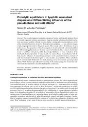
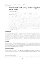
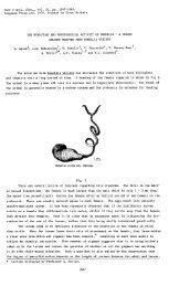
Figure 1. (a) Separation of monolayer S (sensitizer) and A (acceptor); (b) contacting monolayer<br />
S (side with hydrocarbon chain ends) with monolayer A'; (c) contacting monolayer S (side with<br />
chromophores) with monolayer A'. The monolayers (mixed monolayers of stearylsubstituted<br />
dye and arachidic acid, in molar mixing ratio 1:10) are represented schematically, omitting<br />
arachidic acid molecules. The chains of the fatty acid molecules and the hydrocarbon substituents<br />
of the dye molecules are tightly packed in the layer and oriented parallel to each other<br />
and perpendicular to the layer plane.<br />
f Rothen4 reported a separation of monolayers to occur within molecular accuracy in<br />
systems of proteins and lipids, when using a Scotch Tape stripping technique ('molecular<br />
microtome').<br />
422
<strong>CHROMOPHORES</strong> <strong>IN</strong> MONOLAYER ASSEMBLIES<br />
Mixed monolayers of dyes S and A (Figure 1) and arachidic acid, which have<br />
a well defined and compact structure2, are deposited on a glass plate<br />
according to Figure 1 and a polyvinylalcohol film superposed. The film is<br />
stripped off as shown in Figure 1 a and it may be demonstrated that the<br />
separation occurs between the two layers:<br />
In the part to the right the two layers are in contact on the plate. When<br />
irradiating with UV light, which is absorbed by S, the blue fluorescence of S<br />
is largely quenched and the yellow fluorescence of A is observed. In the part<br />
on the left the sensitizer layer is stripped off. The film shows the strong blue<br />
fluorescence of S, demonstrating the S-layer to be stripped off with the film.<br />
The glass plate with layer A appears black since A does not absorb the<br />
incident radiation and thus does not fluoresce. However, when we excite<br />
with light absorbed by A a uniform yellow fluorescence of the glass plate in<br />
both parts is observed showing that a layer is present on the glass plate<br />
where the S-layer is stripped off3.<br />
By setting the stripped film back onto the plate a reassembling of the dye<br />
monolayers in the molecular scale is possible (Figure 1 b): the fluorescence<br />
of S is quenched and the sensitized fluorescence of A is observed at the<br />
touching parts, which appear like the part where the polymer film has not<br />
been stripped off, demonstrating a molecular contact of the layers. The layer<br />
fixed at the polymer film may be brought into contact with any other monolayer<br />
A' on a support. Again the molecular contact is indicated by the<br />
appearance of the sensitized fluorescence. In this example the neighbour<br />
molecules on one side of the monolayer of dye S were changed.<br />
It is also possible to change, in a controlled way, the molecules attaching<br />
to the second side of the same monolayer. The polymer film is dissolved<br />
according to Figure 1 c and then the second side of the polymer is brought<br />
into contact with an appropriate acceptor. Again a fluorescence quenching<br />
CHCH-CH
1W142 KflHI4<br />
01 itiiq it acuawscq UffOLC2CCUCC 01, V !2 02CLAC 2JJ0MJ1J 4JJS4 ii WOJCCIIJSL<br />
C01145C4 itt TP!2 accouq aiqe o tpc mouojitAci 01, cliii 1J20 pe SCJJCACj<br />
ipeac cxbcipncuta CJCWOIJ24LS4C 0tt citaijk UJOIJOISACL2 CSU JX WSU!bfIjstcq'<br />
ipe boaaip!JI4A 01 C0U24L1IC4IIJR WOIJOJSACL itaacmppca 01 ituA combjr-<br />
cntcq SLCP!4CCWLC 0U S JS22 bjatc 0 L1U1IJ U OIJ4O it IAS4CL atiqcc ituq Oj,<br />
twuaLcLL!u it to itiiA SbbLObLiitfC arrp2tLvnC mitl )G fI2C1,fIJ W pmjqm<br />
OL&ruiscq aAacma eA it22CwpJ1IJ bic1,ffpucittcq ejemduta'<br />
1P C0IJtLOJJG )O1tJ11J ituq LCIJJOASJ 01 mouoJSAcLa mitA itjao pc itcjnctcq<br />
pA pLIIJIu aoitb pnppJCa !"t° C0IJ4SC ituq acipacdcicuijA acbituriu pcm<br />
('ttIns ); acxtitcc itcpAc UDOLC2CCU4 qXca !uC0th0Litt1 u 4JJC 2flL1,SCC JSACL2<br />
01 4JJC pnppjca SLC U04 tLitU21,CLLC 1,L0W OTJC pnppjc 40 4JJC O4JJCL 2JJ0EEJIJ 4JJ114<br />
tpc mouoiitAcL2 MJJCJJ L0flJJt !1J40 C01J4&C4 qo U0t LCSLLSUC ituq ipitt tpc<br />
qAc LIJOJCCIIJC2 SLC U04 CXCJJSJJC C4ffiCCU 4JJC t011CJMIJ UJOIIOJSACL2 jIJ 4JJ!2<br />
it IJCM boaaipiptA 01 10Lm!u P!IJJOJCCTIJSL jibic WCUJLSIJC2 !2 OJUitIIJGcF<br />
flnJ!j(C 4JJC WCIJJLit1JC2 opwiucq ?s 4JJC JCUOIAJJ tccpIJidrica 4J1C20 WCWL11IJC2<br />
mitA pe maqe itaMjJmcuc<br />
(P) WO$W NouopActa<br />
ju tpc CS2G 01, bLo4crn mouojitActa flJC m&uibnjitcrou itIJq COIJ24LRC4IOU 01,<br />
oLitIJiscq naacmppca 12 01, B11LIICRJSL IU4CLC24 LC9tqTU 4JJC!L 1mb11Cit410U2<br />
IOL S 2AJJ4JJC4JC WOJCCHJSL piojoA CAcLitJ biojcjrn JJSAC CGIJ SqaOLpCq in SJJ<br />
cusAmitticitjjA &CfJAC 1,OLIn 114 11 W0IJ0JSACL Him 01 itLt1CjJ11C-itC1 OL mctpXjatenste;<br />
ju tpia PASA cowb&cj J&ACL2 o ipe btociua itic opjitiucq Ipla !<br />
peat 2CGU LOW IJJG CJCCTLOU wxcLotubp 0, tJJC !L0u UCJJ bLotew 1CU.!tTuC<br />
fl ts t C<br />
%: • Ø b<br />
4sa**<br />
ta<br />
,*p;,5 e%,4.<br />
14<br />
4*tV44<br />
#4 p<br />
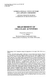
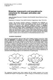
3 EI'-' uncLowbg o btocu ctu;iuc uqaotpcqCU if WOUOJifACL O( WCpAf2çCifLif(C<br />
ifug £I4wcipAjqoqGc)qsuJwoucruJ pLGIJflc{C >LOfGJU WOJCCHJG2 jOLW UJOJJOJUAGL Mijp J0iJ LifuG<br />
jycac jjjm2 puqcq jiyc jyrttA cq initA pe ff2C it2 coin-<br />
boucua 01 otiruncq it22CinC2 o wouoJitXcLa jc ql2crc2a it bo22ipijgA LO<br />
bLonu fpc SLCJJJtCCUILC 01 u 22CIJJpJA p) 2wqArn CIJCLA tL&IJ2ICL i.om it<br />
qAc to s cptowobpouc Lonb in tpc btotcrn; vu &22CIJJpJA JAItJJ flJC IICJJT-<br />
tCCUILC 20th1J W %8LC cs IJJ&A pc cseqA optsiucq L0J10M!U tpc ciq<br />
t3<br />
4
<strong>CHROMOPHORES</strong> <strong>IN</strong> MONOLAYER ASSEMBLIES<br />
procedure. The haem-groups of the protein act as acceptors for the excitation<br />
energy of dye S and quench its fluorescence. The fluorescence being a<br />
measure of the distance between sensitizer and acceptor, the architecture of<br />
the system may be proved. The fluorescence intensity is plotted against an<br />
Blue fluorescence of S<br />
strong quenched<br />
(a) Haemoglobin 0 0 'O<br />
XX d2<br />
—Th --<br />
(b)<br />
ft ft<br />
t I<br />
Ultroviolet rodiation<br />
//////////////////////////////<br />
100<br />
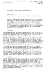
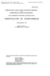
Figure 4. Energy transfer from fluorescing dye S to haemoglobin. (a) Cross section of arrangement.<br />
(b) Intensity of fluorescence of S against doff, where 1/df = ()(dj3 — d3)/(d2 — d1);<br />
experimental points and theoretical curve.<br />
appropriately defined effective distance deff (Figure 4b). The experimental<br />
points lie on the theoretical curve. A monolayer of plasma-albumin was<br />
interposed between sensitizer dye and acceptor haemoglobin7. The pronounced<br />
increase in fluorescence intensity is a measure of the thickness of<br />
this additional interlayer. Its value agrees with expectation. This demonstrates<br />
the possibility of assembling complicated arrangements containing<br />
different proteins.<br />
425<br />
deff
HANS KUHN<br />
2. NATURE <strong>OF</strong> DEACTIVATION PROCESSES<br />
(a) Multipole nature of phosphorescence of dyes<br />
It is well known that the fluorescence of a molecule corresponds to a<br />
dipole emission, but little is known about the multipole nature of a forbidden<br />
transition such as phosphorescence8. There a molecule might act as an<br />
electric quadrupole, magnetic dipole or electric dipole emitter. In all three<br />
cases a long range energy transfer must be expected, the distance—dependence<br />
being different in each case9. Thus, by comparing the experimental distance—<br />
dependence of energy transfer with the theoretical dependence found for each<br />
case, the multipole nature of the phosphorescence may be determined. Since<br />
it was assumed before that an energy transfer. over a large range is only<br />
possible for dipole—dipole interaction, this point shall be discussed in more<br />
detail.<br />
For describing the luminescence and the energy transfer it is advantageous<br />
to use the classical approach. The results, very easily obtained and translated<br />
into quantum mechanical language, agree with those obtained by a more<br />
strict treatment9.<br />
The molecule is described as a classical antenna. The emission power Le<br />
is obtained from the classical electromagnetic theory and is given in Table 1<br />
Table 1. Power emitted and absorbed for various multipole radiations j, m0, Q0, amplitude of<br />
electric dipole, magnetic dipole and electric quadrupole respectively; c the velocity of light,<br />
w = 2itv,, c number of molecules per unit area a a numerical factor discussed following equation<br />
(4)<br />
Emitter Magnetic dipole Electric dipole electric quadrupole<br />
Le emitted power (1/487r2c) 1n02w4 (l/3c3) ito2w4 (1/60c5) Q02w6<br />
Lpower absorbed<br />
by acceptor layer<br />
at distance d 27r<br />
const. =<br />
2<br />
const. x Ct)2 x m0ax<br />
2 const. x /l0aa x<br />
128ir5<br />
const. = ct'<br />
const. x Qao x<br />
128ir7<br />
const. = a6<br />
for the three cases. The probability of an excited molecule emitting a quantum<br />
of light (energy hv2), in the time interval dt, is dPe and is. given by<br />
(1)<br />
dt hv<br />
Now let us put an acceptor molecule at a point near the emitting, antenna.<br />
In the classical picture the emitting molecule produces a certain alternating<br />
electromagnetic field, and F0 shall be the amplitude of the electric field<br />
strength. The power absorbed by the acceptor molecule is<br />
L = aF02 (2)<br />
where constant a depends on the nature of the acceptor molecule and is<br />
related to the extinction coefficient of the molecule for light of frequency v.<br />
The field F0 in the environment of an oscillating multipole is given by<br />
Hertz's solution of the Maxwell equations and in the proximity field region<br />
426<br />
1
<strong>CHROMOPHORES</strong> <strong>IN</strong> MONOLAYER ASSEMBLIES<br />
(at a distance small compared to the wavelength of the luminescent light )),<br />
F0 is simply given by Coulomb's law and the induction laws for electric and<br />
magnetic multipoles respectively (Figure 5). The power absorbed by a layer<br />
r<br />
m0<br />
11 m0a<br />
3Qo —- F0 =—-<br />
Figure 5. Amplitude of electric field (F0) in proximity of oscillating electric dipole (amplitude<br />
po). magnetic dipole (amplitude m0), electric quadrupole (amplitude Q0).<br />
of acceptor molecules, La, is obtained by summing over the contributions<br />
aF02 of each single molecule (Table 1).<br />
Energy transfer and emission being competitive processes, the lifetime of<br />
the excited state is shortened by increasing the amount of energy transfer,<br />
and thus the decay time of the phosphorescence is shortened. The decay time<br />
Td for a distance d between sensitizer and acceptor layer is related to La, Le<br />
and LL(L is the power loss by non-radiative processes, other than the process<br />
of energy transfer to acceptor A):<br />
(L + Lt)/(Le + L, + L0).<br />
The quantum yield of the luminescence, q,, is related to Le and L by<br />
q5 = Le/(Le + U. [When A is absent, q is the probability of a molecule in<br />
the luminescent excited state emitting a photon. q must be distinguished<br />
from q (number of emitted quanta/number of absorbed quanta)]. With the<br />
data in Table 1 the equation<br />
= [1 + (d0/d)] -1 (3)<br />
d0 = ct(Ajn) (A5q)" (4)<br />
is obtained with p 2, 4 and 6 for magnetic dipole, electric dipole, and<br />
electric quadrupole, respectively10. n is the refractive index of the medium.<br />
The value of the numerical factor o depends on the orientation of emitter<br />
and acceptor. Under usual experimental conditions the transition moments<br />
of the acceptor molecules are statistically oriented in the plane of the layer.<br />
Then = 3*/8m for a magnetic dipole and for an electric dipole ranges<br />
between the values 0.098 and 0.12, for an electric quadrupole between the<br />
values 0.14 and 0.21. In the case of a sufficiently narrow luminescence band<br />
427
HANS KUHN<br />
A5 is the absorption (1-transmission) of the acceptor layer. In the general<br />
case, A5 is defined by the expression<br />
A5 = A(v) f5(v) (vjv)4 dv (5)<br />
with f5(v) being the normalized quanta distribution function, and v the<br />
frequency of the maximum of the fluorescence band of the sensitizer; A(v) is<br />
the absorption of A at frequency v. The value of the quantum yield, q, must<br />
lie between 1 and 0.06 since the measured overall quantum yield. q (number<br />
of emitted quanta/number of absorbed quanta) is 0.06. By inserting the<br />
lower limit of q and cx and the upper limit of q5 and cx in equation (4) we find<br />
the results given in Figure 6. The experimental points are given in the figure.<br />
The experimental value d0 = 100A rules out an electric quadrupole or a<br />
magnetic dipole but not an electric dipole radiation. With equation (4) we<br />
S =<br />
H3C<br />
C18H37 C,8H37<br />
A = [_CH=CH_CH=CH_CH=(1{)<br />
I<br />
H37 C!:18H37<br />
—dE $i<br />
Figure 6. Multipole nature of phosphorescence of dye S. Decay time of phosphorescence (tj)<br />
versus distance d between S and layer of acceptor A. Theoretical range for magnetic dipole,<br />
electric dipole and electric quadrupole radiations. Experimental points on theoretical curve for<br />
electric dipoles with appropriate value q.<br />
calculate that the quantum yield for an electric dipole radiation lies between<br />
the values 0.42 (dipole oscillating parallel to the layer plane) and 0.21 (dipole<br />
oscillating perpendicular to the layer plane). Thus the quantum yield q3 is<br />
distinctly higher than the measured overall quantum yield of the phosphorescence,<br />
q = 0.06.<br />
The results may be checked by another method (not discussed here) based<br />
on the monolayer assembling technique: measuring the directional pattern<br />
428
<strong>CHROMOPHORES</strong> <strong>IN</strong> MONOLAYER ASSEMBLIES<br />
of the phosphorescence as a function of the distance between the emitting<br />
molecule and a metal mirror2' 10, 11<br />
It would be of interest to realize experimentally the quadrupole emitter,<br />
since it should result in a considerably larger range of energy transfer than<br />
the electric dipole.<br />
(b) Luminescence lifetime in the proximity of an interface<br />
We have considered the shortening of the lifetime of the excited state by a<br />
transfer of energy to an acceptor. A surprising effect may be demonstrated<br />
related to energy transfer with the monolayer assembling technique:<br />
changing the lifetime of the excited state without changing the luminescence<br />
quantum yield12. The decay time of the luminescence is found to be dependent<br />
on the distance between emitter and and the interface of two differently<br />
polarizable dielectrics13. It may be shortened or lengthened depending on<br />
this distance. Thus the average lifetime of the excited state of a molecule or<br />
the probability (dPe) of exciting a quantum of light depends on the broad<br />
environment of the molecule. The process of emitting the light quantum does<br />
not only depend on the excited molecule, but on the total system of molecule<br />
plus its environment. The excited molecule, so to say, knows all about its<br />
surroundings when it decides to emit a quantum of light. This experiment<br />
constitutes an unusual manifestation of the wave—particle duality of light.<br />
For a quantitative consideration it is advantageous to use again the<br />
classical picture and equation (1) for translating the result into the quantum<br />
mechanical language.<br />
First let us again look at the energy transfer from an excited molecule S<br />
described as an oscillating dipole to an acceptor A in the alternating field of<br />
±<br />
S<br />
Non-absorbing<br />
___________ :molecule<br />
I<br />
Figure 7. Fluorescent molecule S and acceptor molecule A (a) or non-absorbing molecule (b).<br />
Classical picture neglecting retardation effect. Phase shift between oscillators S and A in case (a),<br />
in-phase oscillation of oscillators in case (b).<br />
S (Figure 7a). A may be described as a damped oscillator. It will oscillate<br />
with a phase shift relative to S. The field of A damps S and therefore diminishes<br />
the decay time of S: energy is transferred from S to A.<br />
429
HANS KUHN<br />
A is now substituted for a non-absorbing molecule. It will oscillate in<br />
phase with S, and thus does not damp S (Figure 7b). However, this statement<br />
is not completely correct, since the electromagnetic field needs some time to<br />
reach the non-absorbing molecule and the echo field to reach S. This echo<br />
field has an accelerating or retarding effect on S depending on this phase<br />
shift between echo field and elongation of S. Thus the molecule, even when<br />
not absorbing energy, influences the decay time of S.<br />
In the case of an absorbing molecule A, its influence on the emission<br />
power Le is negligible and the decrease of the decay time is determined by<br />
the absorbed power La. For a non-absorbing molecule, La = 0, but the<br />
0.9<br />
0.7-<br />
\i' \<br />
rI Ir—<br />
hv<br />
0 1000 2000 3000<br />
d[.XJ<br />
Figure 8. Red luminescent europium complex at distance d from fatty acid/air interface. Lifetime<br />
of luminescence (td) as a function of d. Theoretical curve and experimental points. The<br />
quantum yield of the luminescence being constant and equal to 1, t is markedly dependent on<br />
d. This effect is caused by the time the electromagnetic radiation needs to travel from the<br />
emitter to the neighbouring polarizable molecules and the echo by these molecules to travel to<br />
the emitter, i.e. a time of the order of(3 x lO6cm)/(3 x 1010 om/sec) 1016sec.<br />
influence of this molecule on the radiative decay process of S is important. This<br />
process then must be considered as being due to the system of both molecules.<br />
In the case of many non-absorbing molecules, a dielectric extending over<br />
the shaded part in Figure 8, we have to sum up over the echoes of each<br />
molecule and, for a particular case, the curve in Figure 8 is obtained for the<br />
decay time (td) as a function of the distance between emitter and interface<br />
(d)13 The experimental points correspond to the measured decay times of<br />
samples obtained by depositing a monolayer of a strongly luminescent<br />
europium complex on a glass plate and superposing on it fatty acid monolayers<br />
(fatty acid and glass have almost the same refractive index).<br />
The theoretical curve is obtained by assuming a quantum yield q3 = 1<br />
(this value was obtained by energy transfer experiments2) and the good<br />
agreement between theory and experiment substantiates the value. The<br />
resulting theoretical curve depends strongly on q and thus this type of<br />
experiment is useful as a method for determining q, which is otherwise<br />
430
<strong>CHROMOPHORES</strong> <strong>IN</strong> MONOLAYER ASSEMBLIES<br />
difficult to determine. Similar experiments with a metal surface as interface<br />
have been described elsewhere9' 12<br />
3. LIGHT ABSORPTION <strong>OF</strong> AGGREGATES <strong>OF</strong> DYES <strong>IN</strong><br />
MONOLAYER ASSEMBLIES<br />
(a) Absorption by sandwich-pair aggregates<br />
In the foregoing part we studied the weak interaction of molecules at<br />
relatively large separations. In the following we consider molecules in<br />
direct contact. Using the monolayer assembling technique, sandwich-pair<br />
arrangements of identical or different dye molecules may be studied 14 The<br />
experimental band shifts and changes in oscillator strength were found to be<br />
in quantitative agreement with the values calculated using a refined onedimensional<br />
electron gas model1 5• Table 2 gives, for some cases, the theo-<br />
Table 2. Shifts (nm) of some Scheibe-type aggregates Lp) and dimers (2D) with respect to the<br />
corresponding monomers M)<br />
)— 'M 'D 2<br />
theor. exp. theor. exp.<br />
I1i1J +54<br />
HI<br />
C37H1 C18H37<br />
jj,)_c=(jjj<br />
I<br />
H37C18 C18H37<br />
I I<br />
H17C18 C181-137<br />
+40 —30 —40<br />
+ 23 + 25 —18 —25<br />
+ 23 +19 —18 —16<br />
retical and observed shifts 2D — AM between the absorption peak of the<br />
dimer LD) and of the monomer (AM). Based on this approach is the following<br />
assumption which highly facilitates calculation:<br />
The g-electrons of the dye molecule and of the surrounding solvent molecules<br />
are treated as an infinite medium of dielectric constant 2.5 and the it-electrons<br />
are considered as being in this medium and as moving along the zigzag lines<br />
in Figure 9, i.e. along the lines of highest it-electron density.<br />
431
zI<br />
HANS KUHN<br />
,/ / /NCN<br />
Figure 9. Model used to calculate molecular aggregate spectra ihown for simplest cyanine in<br />
sandwich arrangement.<br />
(b) Absorption by Scheibe-dye aggregates<br />
This model may be applied to the Scheibe-dye aggregates (i-aggregates)'6<br />
characterized by a very narrow and high absorption peak corresponding to<br />
an in-phase oscillation of the oscillators substituting each dye molecule' .<br />
In the well known case of pseudo-isocyanine (Figure 1O this peak has a<br />
bathochromic shift of 53 nm relative to the monomer peak.<br />
The aggregate structures shown in Figures lOa and b have been proposed<br />
I I I A—A P M[nm]=<br />
+53<br />
(experimental)<br />
N'CH N<br />
C2H5 C2H5<br />
_<br />
Q) r-5F b) _____<br />
APAMIflm]<br />
—40 —52<br />
__ I UH<br />
Figure 10. Scheibe—aggregate forming dye pseudoisocyanine. Experimental and theoretical<br />
values for aggregate to monomer band shift — ZM. (a) staircase arrangement; (b) ladder<br />
arrangement; (c) brick-stonework arrangement.<br />
in the past'6. Assuming these structures, the electron gas model calculation<br />
gives hypsochromic instead of bathochromic shifts'8. However, when the<br />
structure shown in Figure lOc (a brick-stonework-like arrangement of the<br />
dye molecules) is assumed the model calculation gives a bathochromic shift<br />
of 44 nm, which is in approximate agreement with experiment. It is a well<br />
known fact that the formation of Scheibe-dye aggregates is facilitated by<br />
bulky meso—substituents. This fact is explained by the brick-stonework<br />
model, which allows a tight packing of the molecules.<br />
Keeping in mind this new structural concept, let us try to find a way to<br />
get Scheibe-aggregates of dyes by appropriately arranging the molecules in<br />
432<br />
C)
23IJffMH2A<br />
SHYAJO14OM<br />
MI<br />
aaROHOMOMHD<br />
nwoni<br />
ton<br />
asb<br />
sninso<br />
fislutilaclna<br />
1tssta<br />
tsbiano3<br />
sW<br />
Y<br />
'is'stonom<br />
silt<br />
sd<br />
sm<br />
sioilqomoirb<br />
silT<br />
i<br />
snsR<br />
iii<br />
a<br />
s'b<br />
as<br />
iloiJa<br />
gnnnol<br />
s1ssis<br />
as<br />
ni<br />
nsvi<br />
anoiansmib<br />
srI<br />
1<br />
(11kw<br />
told<br />
lsIugrIsl3sl<br />
s<br />
as<br />
'llsoitsmsrba<br />
bswskv<br />
islsmsib<br />
io<br />
a1sbnu13<br />
as<br />
alnsutitadua<br />
nothssoThl(cl<br />
owt<br />
sill<br />
fins<br />
ii<br />
siucR<br />
zlno<br />
al<br />
asioriqomotib<br />
sill<br />
10<br />
nitsq<br />
saolo<br />
B<br />
ct<br />
sisxR<br />
ol<br />
nib1oa3A<br />
A<br />
a<br />
sloflqomolfl3<br />
5(11<br />
illivi<br />
lnsmsansnn<br />
s)li1-towsnota-tfld<br />
s<br />
wi<br />
sldiaaoq<br />
2<br />
wsiv<br />
sbi2<br />
bRo-id<br />
cii<br />
slusslom<br />
silCI<br />
(s)<br />
.isslonom<br />
iii<br />
nourartuol<br />
st<br />
s1s-stb-scfi3rI3<br />
.1<br />
yd<br />
aquoig<br />
limoti<br />
told<br />
isluansissi<br />
d<br />
bs3Emixoiqq<br />
asioilqomoudD<br />
.wsiv<br />
ss-atbiid<br />
bus<br />
orb<br />
iii<br />
nittfl<br />
misdo<br />
snsosbstoo<br />
asiodqomo<br />
trio<br />
lo<br />
tnoms3rrsns<br />
tovenotm—titfl<br />
(ci)<br />
.nthnibco<br />
.s'b<br />
silt<br />
10<br />
einsuiitmdu2<br />
hpsst<br />
silt<br />
d<br />
isvo<br />
fist<br />
aslorl<br />
Isoj-ibnilo<br />
gnol<br />
siorlqomotrlo<br />
silt<br />
fins<br />
snslq<br />
iss1onom<br />
silt<br />
ol<br />
isluDibnsqisq<br />
asnslq<br />
lasaolo<br />
ii<br />
issl<br />
sldsta<br />
s<br />
ol<br />
bssl<br />
bluoila<br />
tnsmsgnsrrs<br />
aiilT<br />
.IslIstsq<br />
asxs<br />
lsm<br />
ai<br />
noitibno3<br />
airlT<br />
.bsvskrlos<br />
oafs<br />
ai<br />
anisrlo<br />
nothssoibrl<br />
sill<br />
lo<br />
nitsq<br />
d<br />
tsvo<br />
usE<br />
siutsuila<br />
silt<br />
lo<br />
sloil<br />
ilsss<br />
olni<br />
nisila<br />
noths3o1brl<br />
£<br />
nulluq<br />
'(d<br />
siulxzrn<br />
1:<br />
1<br />
B<br />
nibsstqa<br />
d<br />
si<br />
!asluoslom<br />
s'cb<br />
silt<br />
1<br />
ainsuliladsa<br />
Itissla<br />
sill<br />
-thd<br />
silT<br />
.(c\<br />
It<br />
swickk)<br />
snssbsloo<br />
as<br />
iloua<br />
nothsoibrl<br />
s<br />
fins<br />
sib<br />
aiill<br />
10<br />
'llss-i<br />
sis<br />
fins<br />
titi<br />
airll<br />
td<br />
fism-rol<br />
sd<br />
ol<br />
bsoioi<br />
515<br />
aslsgsigs<br />
howsnola<br />
nibinios<br />
homEs<br />
sill<br />
fins<br />
bnsd<br />
noilqioads<br />
wonsn<br />
Es3iq'(t<br />
sill<br />
°<br />
'bs'rts<br />
ado<br />
jsbom<br />
sill<br />
cl<br />
fisnislqxs<br />
as<br />
bnsd<br />
silT<br />
.(&<br />
t<br />
snxck)<br />
tuoso<br />
bnsd<br />
s3nstasloufl<br />
.oils-t<br />
anixirn<br />
nodisooibrl<br />
ot<br />
sb<br />
sill<br />
io<br />
sgnst<br />
[lucia<br />
s<br />
nirlliw<br />
'1no<br />
amsqqs<br />
fissrl<br />
isloq<br />
s<br />
anivsrl<br />
insnoqmoa<br />
nixim<br />
5<br />
(11kw<br />
eansLonom<br />
bsxirn<br />
io'l<br />
sill<br />
(dL<br />
I<br />
siucII)<br />
bs'nsado<br />
ion<br />
ai<br />
>Issq<br />
stsgsiggs<br />
sfi—sdisdoa<br />
sill<br />
quotg<br />
siutsinla<br />
sill<br />
ni<br />
sloil<br />
£<br />
aissid<br />
lnsnoqmo3<br />
anixim<br />
sill<br />
lo<br />
quoi<br />
fissil<br />
isloq<br />
-sdisiloa<br />
on<br />
fins<br />
sldiaaoq<br />
ai<br />
siuloirtla<br />
lDsqmo3<br />
on<br />
a-ts's1onom<br />
sb<br />
siuq<br />
ni<br />
fins<br />
Essilsiosrll<br />
sill<br />
asass<br />
srnoa<br />
tol<br />
awoila<br />
\dnT<br />
.bsvtsado<br />
sis<br />
aslsgsigs<br />
EEls<br />
(p)<br />
iii,
HANS KUHN<br />
experimental shift — of the peak of the Scheibe-dye-aggregates ()<br />
with respect to that of the monomer<br />
In the case of carbocyanine dyes, which have two additional methine<br />
groups in the chain, a closely packed structure of mixed monolayers of dye<br />
(a) dye/C17H35CH3<br />
1/1<br />
300<br />
(b) dye/C17H35000H<br />
1/1<br />
300<br />
Absorption<br />
Absorption<br />
400<br />
400<br />
—* Wave length<br />
CCH=
<strong>CHROMOPHORES</strong> <strong>IN</strong> MONOLAYER ASSEMBLIES<br />
A shift proportional to the applied field and a contribution proportional<br />
to the square of the field may be distinguished. The first contribution<br />
measures the difference between the dipole moment of the excited state and<br />
the ground state of the molecule, the second the change in polarizibility.<br />
The band shift is obtained by measuring the absorption change as a<br />
function of the frequency of the incident light (Figure 14). (In order to ensure<br />
a simple situation it is necessary to keep the distance between the aluminium<br />
electrodes such that the system has the property of an interference filter). In<br />
the example of Figure 14 the values Au 0.07 Debye and Ac = 1.5 A3<br />
are obtained from the linear and quadratic contributions, respectively.<br />
In the known methods for obtaining information on these quantities, in<br />
contrast to the present method, the molecules are oriented in an electric<br />
field2t. Then both polarizibility and dipole moment changes produce band<br />
(a) (b)<br />
ggllgggggggggggggggl<br />
111111<br />
I I Ill$lI V F<br />
+<br />
_______ ______ ___________+<br />
_______<br />
E Surfaceactive cyanine dye<br />
Cd—orachidate — Octudecane<br />
t4 Semitransparent Al—electrodes<br />
Figure 13. (a) Cross section through capacitor for measuring electrochromism. A single monolayer<br />
of Scheibe-dye-aggregate forming cyanine sandwiched between monolayers of cadmium<br />
arachidate and semitransparent electrodes. (b) Dye molecule in electric field. When light is<br />
absorbed negative charge moves in direction of arrow.<br />
shifts proportional to the square of the field. For this reason it is not possible<br />
to measure polarizibility changes by these methods.<br />
Theoretical values for ttu and Ac of the dye in Figure 14, obtained by<br />
an electron gas model calculation (Etu 0.2 Debye, JXcc = 3A3), have the<br />
same sign and similar absolute values as the above experimental data.<br />
In the case of the linear contribution the essentials of the calculation are<br />
seen by considering the electron clouds given by the electron gas model in<br />
its simplest form, neglecting the branching of the it-electron system. The<br />
chromophore system then extends over the, shaded area in Figure 15. The<br />
wave function of the highest occupied state has a wave with three antinodes,<br />
the next state four antinodes. By inspecting the electron clouds in both states<br />
it is immediately seen that the centre of gravity of the cloud, when exciting<br />
the chromophore, is shifted in the direction of the arrow in Figure 13b.<br />
435<br />
—
HANS KUHN<br />
In the presence of an eleciric field, with a direction as indicated in Figure<br />
13b, the excitation energy AE is decreased, since the excitation of the<br />
molecule moves negative charge towards the positive electrode. Thus the<br />
absorption band of each single molecule is shifted to the red when applying<br />
the voltage. This causes a corresponding shift of the aggregate band: in the<br />
I<br />
ox<br />
OL<br />
n.<br />
.a)<br />
(n'<br />
0.01 Lf<br />
- C18H37 C18H37<br />
3x10³<br />
2x10³<br />
lxl0<br />
0<br />
7.5 x 10'<br />
—)- v[sec1)<br />
Linear electrochrornism<br />
(contribution proport. F)<br />
Figure 14. Electrochromism of cyanine dye. (a) Absorption A(v) of monolayer on a glass plate;<br />
(b) Monolayer in condenser of Figure 13. Absorption change EA(v) induced in electric field of<br />
5 x 10⁶ V/cm. Contribution proportional to F (full curve); contribution proportional to F2<br />
(dashed curve).<br />
classical picture the dipole substituting the dye oscillates slower and,<br />
consequently, the frequency of the coupled in-phase oscillation corresponding<br />
to the aggregate band is slower. When the polarizability of the<br />
applied voltage is reversed, the excitation energy is increased.<br />
436<br />
(a)<br />
(b)<br />
Quadratic etectrochromism<br />
(contribution proport. F2)
<strong>CHROMOPHORES</strong> <strong>IN</strong> MONOLAYER ASSEMBLIES<br />
Figure 15. Dye in Figure 14. Portion of chromophore taken into account in model calculation<br />
(shaded area). Proceeding from highest occupied orbital (three antinodes) to next orbital (four<br />
antinodes), the centre of gravity of electron cloud moves in direction from top to bottom.<br />
REFERENCES<br />
1 M. M. Zwick and H. Kuhn. Z. Naturforsch. 17a, 411 (1962); K. H. Drexhage, M. M. Zwick<br />
and H. Kuhn. Ber. Th4nsenges. Phys. Chem. 67, 62 (1963).<br />
2 H. Bücher, K. H. Drexhage, M. Fleck, H. Kuhn, D. Möbius, F. P. Sbhäfer, J. Sondermann,<br />
W. Sperling, P. Tillmann.and J. Wiegand. Mol. Cryst. 2, 199 (1967).<br />
H. Bdcher, H. Kuhn, B. Mann, D. Möbius, L. v. Szentpály and P. Tillmann. Photogr. Sci.<br />
Engng. 11.233 (1967); Equation (8) should read E = KA(ln 10)-' and in the equation following<br />
(8), instead ofx = (3/47r)[(In)/24]* = 0.133, read = (3/4it)[(ln 10)361* = 0.120.<br />
H. Bücher, 0. v. Eisner, D. Möbius, P. Tillmann and J. Wiegand. Z. Physik. Chem. N. F.<br />
65, 152 (1969).<br />
0. Inacker, D. Möbius and H. Kuhn. In print.<br />
A. Rothen. J. Phys. Chem. 63, 1929 (1959); Biochim. Biophys. Acta 88, 606 (1964); Physical<br />
Techniques in Biological Research D. H. Moore, Ed., Vol. II, Part A, 2nd ed., Academic<br />
Press, New York and London, 1968, p. 217.<br />
W: Mormann and H. Kuhn. Z. Naturforsch. 24b, 1340 (1969).<br />
6 P. Mueller, D. 0. Rudin, H. T. Tien and W. C. Wescott in Recent Progress in Surface Science<br />
Vol. 1. Academic Press, New York, London 1964, Ch. II.<br />
P. Fromherz. FEBS Letters, 11,205 (1970); Nature, Lond. .231,267 (1971); Biochim. Biophys.<br />
.4cta, 225, 382 (1971).<br />
8 S. Freed and S. I. Weissmann. Phys. Rev. 60, 440 (1941); S. I. Weissmann and D, Lipkin.<br />
J. Am. Chem. Soc. 64, 19t6 (1942).<br />
H. Kuhn, J. Chetn. Phys. 53. 101 (1970).<br />
'° 0. Inacker, H. Kuhn, H. Bücher, H. Meyer and K. H. Tews. Chem. Phys. Lett. 7,213 (1970).<br />
Instead of q3 = 0.14 in first line of left row on page 215, read q, = 0.41.<br />
" M. fleck. Thesis, University of Marburg, 1968; K. H. Drexhage, M. Fleck and H. Kuhn.<br />
&r. ThAnsenges. Phys. Chem. 71, 915 (1967).<br />
12 K. H. Drexhage, M. Fleck, H. Kuhn, F. P. Schafer and W. Sperling. Ber. ThAnsenges. Phys.<br />
Chen. 70,1179 (1966); K. H. Drexhage, H. Kuhn, F. P. Schafer. Ber. Thsnsenges. Phys Chem.<br />
72, 329 (1968);<br />
437
HANS KUHN<br />
13 K. H. Tews, 0. Inacker and H. Kuhn. Nature 909,276(1970). Equation (5) contains a printing<br />
error. Instead of x(sin(x) — nJ2) read: x(Si(x) — ir/2);instead of 'ref. 5' in the third paragraph<br />
read 'ref. 6'.<br />
14 H. Kuhn. Naturwissenschaften 54, 429 (1967).<br />
15 V. Czikkely, G. Dreizier, H. D. Försterling, H. Kuhn, J. Sondermann, P. Tillmann and<br />
1. Wiegand. Z. Naturforsch. 24a, 1821(1969).<br />
16 0. Scheibe. Angew. Chern. 52, 633 (1939); 0. Wörz and 0. Scheibe. Z. Naturforsch. 24b 381<br />
(1969).<br />
'Th. Förster. Naturwissenschaften 33, 166 (1946); E. 0. McRae and M. Kasha. J. Cheat.<br />
Phys. 28, 721 (1958).<br />
18 V. Czikkely, H. D. Forsterling and H. Kuhn. Cheat. Phys. Lett. 6, 11 (1970)<br />
19 H. Bücher and H. Kuhn. Cheat. Phys. Lou. 6, 183 (1970).<br />
20 H. Bucher and H. Kuhn. Z. Naturforsch. 25b, 1323 (1970).<br />
21 See e.g. W. Liptay. Angew. Cheat. 81, 195 (1969); K. Siebold, H. Navangul and H. Labhardt.<br />
Cheat. Phys. Lett. 3, 275 (1969).<br />
438