TI-KVIV « Praktijk van de grondmechanica en funderingstechniek ...
TI-KVIV « Praktijk van de grondmechanica en funderingstechniek ...
TI-KVIV « Praktijk van de grondmechanica en funderingstechniek ...

Create successful ePaper yourself
Turn your PDF publications into a flip-book with our unique Google optimized e-Paper software.
ISSMGE - TC 211 International Symposium on Ground Improvem<strong>en</strong>t IS-GI Brussels 31 May & 1 June 2012<br />
ABSTRACT<br />
15 years of experi<strong>en</strong>ce with geotextile <strong>en</strong>cased granular columns<br />
as foundation system<br />
Dimiter Alexiew, HUESKER Synthetic GmbH, Gescher, Germany, dalexiew@huesker.<strong>de</strong><br />
Marc Raithel, Kempfert + Partner Geotechnik, Würzburg, Germany, m.raithel@kup-geotechnik.<strong>de</strong><br />
Volker Küster, Josef Möbius Bau-Akti<strong>en</strong>gesellschaft, Hamburg, Germany,<br />
volker.kuester@moebiusbau.com<br />
Oliver Detert, HUESKER Synthetic GmbH, Gescher, Germany, <strong>de</strong>tert@huesker.<strong>de</strong><br />
The Geotextile Encased Column (GEC) foundation system for earthwork structures built on soils of low<br />
bearing capacity was launched onto geotechnical <strong>en</strong>gineering some 15 years ago and is now consi<strong>de</strong>red<br />
state-of-the-art in Germany. The GEC system provi<strong>de</strong>s a geotechnical foundation solution for weak and<br />
very weak soils where more traditional ground improvem<strong>en</strong>t techniques are unlikely to be viable. This<br />
paper provi<strong>de</strong>s a system <strong>de</strong>scription, the required <strong>de</strong>sign procedure and <strong>de</strong>tails of ongoing long-term<br />
monitoring. Information is also inclu<strong>de</strong>d on the continuous improvem<strong>en</strong>ts which have be<strong>en</strong> ma<strong>de</strong> to the<br />
GEC system in response to the technical and financial requirem<strong>en</strong>ts of large civil <strong>en</strong>gineering projects as<br />
well as curr<strong>en</strong>t pot<strong>en</strong>tial and research directions and the curr<strong>en</strong>t regulations and gui<strong>de</strong>lines governing<br />
use of the system in Germany. In the future, GECs are likely to be used world-wi<strong>de</strong> for water and land<br />
<strong>en</strong>gineering projects in very soft soils.<br />
1. INTRODUC<strong>TI</strong>ON<br />
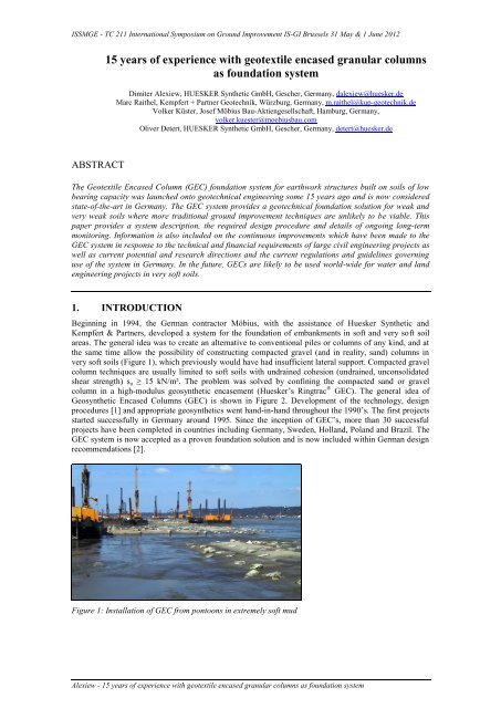
Beginning in 1994, the German contractor Möbius, with the assistance of Huesker Synthetic and<br />
Kempfert & Partners, <strong>de</strong>veloped a system for the foundation of embankm<strong>en</strong>ts in soft and very soft soil<br />
areas. The g<strong>en</strong>eral i<strong>de</strong>a was to create an alternative to conv<strong>en</strong>tional piles or columns of any kind, and at<br />
the same time allow the possibility of constructing compacted gravel (and in reality, sand) columns in<br />
very soft soils (Figure 1), which previously would have had insuffici<strong>en</strong>t lateral support. Compacted gravel<br />
column techniques are usually limited to soft soils with undrained cohesion (undrained, unconsolidated<br />
shear str<strong>en</strong>gth) su ≥ 15 kN/m². The problem was solved by confining the compacted sand or gravel<br />
column in a high-modulus geosynthetic <strong>en</strong>casem<strong>en</strong>t (Huesker’s Ringtrac ® GEC). The g<strong>en</strong>eral i<strong>de</strong>a of<br />
Geosynthetic Encased Columns (GEC) is shown in Figure 2. Developm<strong>en</strong>t of the technology, <strong>de</strong>sign<br />
procedures [1] and appropriate geosynthetics w<strong>en</strong>t hand-in-hand throughout the 1990’s. The first projects<br />
started successfully in Germany around 1995. Since the inception of GEC’s, more than 30 successful<br />
projects have be<strong>en</strong> completed in countries including Germany, Swe<strong>de</strong>n, Holland, Poland and Brazil. The<br />
GEC system is now accepted as a prov<strong>en</strong> foundation solution and is now inclu<strong>de</strong>d within German <strong>de</strong>sign<br />
recomm<strong>en</strong>dations [2].<br />
Figure 1: Installation of GEC from pontoons in extremely soft mud<br />
Alexiew - 15 years of experi<strong>en</strong>ce with geotextile <strong>en</strong>cased granular columns as foundation system
ISSMGE - TC 211 International Symposium on Ground Improvem<strong>en</strong>t IS-GI Brussels 31 May & 1 June 2012<br />
Figure 2: G<strong>en</strong>eral i<strong>de</strong>a of embankm<strong>en</strong>t on soft soil set on Geosynthetic Encased Columns (GEC)<br />
2. GEC - SYSTEM DESCRIP<strong>TI</strong>ON<br />
By the GEC-columns the main part of the load from the embankm<strong>en</strong>t will be transferred directly through<br />
the soft soil down to a firm stratum. Embankm<strong>en</strong>ts on concrete, steel, and woo<strong>de</strong>n piles are nearly<br />
settlem<strong>en</strong>t-free. The compression stiffness of the piles is so high, that practically no settlem<strong>en</strong>t occurs at<br />
the level of pile tops or caps. High str<strong>en</strong>gth horizontal geosynthetic reinforcem<strong>en</strong>t is typically installed<br />
above the piles to bridge over the soft soil betwe<strong>en</strong> piles and equalize the embankm<strong>en</strong>t’s <strong>de</strong>formations.<br />
The vertical compressive behavior of the GECs is less rigid. The compacted vertical sand or gravel<br />
column starts to settle un<strong>de</strong>r load mainly due to radial outward <strong>de</strong>formation. The geosynthetic<br />
<strong>en</strong>casem<strong>en</strong>t, and to some ext<strong>en</strong>t the surrounding soft soil, provi<strong>de</strong>s a confining radial inward resistance<br />
acting similar to the confining ring in an oedometer, but being more ext<strong>en</strong>sible. The mobilization of ringforces<br />
requires some radial ext<strong>en</strong>sion of the <strong>en</strong>casem<strong>en</strong>t (usually in the range of 1 to 4 % strain in the ring<br />
direction) leading to some radial “spreading” <strong>de</strong>formation in the sand (gravel) columns and resulting<br />
consequ<strong>en</strong>tly in vertical settlem<strong>en</strong>t of their top.<br />
The GEC system therefore cannot be completely settlem<strong>en</strong>t-free. Fortunately, most of the settlem<strong>en</strong>t<br />
occurs during the construction stage and is comp<strong>en</strong>sated by some increase of embankm<strong>en</strong>t height. Finally,<br />
<strong>en</strong>sured by the str<strong>en</strong>gth and stiffness of sand or gravel, confining ring-force in the <strong>en</strong>casem<strong>en</strong>t and soft<br />
soil radial counter-pressure, a state of equilibrium is reached.<br />
The specific characteristics of the GEC system are:<br />
1. The primary function of the high-modular high-str<strong>en</strong>gth geotextile <strong>en</strong>casem<strong>en</strong>t is the radial confining<br />
reinforcem<strong>en</strong>t of the bearing (sand or gravel) column.<br />
2. The secondary functions of the <strong>en</strong>casem<strong>en</strong>t are separation, filtration and drainage.<br />
3. The system is not completely settlem<strong>en</strong>t-free.<br />
4. The GEC is typically an <strong>en</strong>d-bearing elem<strong>en</strong>t transferring the loads to a firm un<strong>de</strong>rlying stratum.<br />
5. The GECs are water-permeable; they practically do not influ<strong>en</strong>ce the flow of groundwater streams,<br />
which has pot<strong>en</strong>tial ecological ad<strong>van</strong>tages.<br />
6. The GECs may also perform as high-capacity vertical drains.<br />
7. The geotextile <strong>en</strong>casem<strong>en</strong>t is a key bearing / reinforcing elem<strong>en</strong>t, capable of meeting high quality<br />
<strong>en</strong>gineered <strong>de</strong>sign standards and specifications.<br />
8. It is strongly recomm<strong>en</strong><strong>de</strong>d to install horizontal geosynthetic reinforcem<strong>en</strong>t on top of the GECs (at<br />
the base of the embankm<strong>en</strong>t). The horizontal reinforcem<strong>en</strong>t is used for the global stability, for<br />
transferring spreading forces or to facilitate load transfer into the columns.<br />
The GEC foundation system was specially <strong>de</strong>veloped for earthwork structures built on weak and very<br />
weak subsoil. It comprises uniformly arranged columns, filled with non-cohesive material and <strong>en</strong>closed in<br />
a geosynthetic sleeve, which transmit the structural loads to the bearing stratum (Figure 2).<br />
The overall loads and stress conc<strong>en</strong>trations above the column heads induce outwardly directed radial<br />
horizontal stresses in the columns. The particularity of the GEC system is that these stresses are<br />
counteracted not only by the inwardly acting pressure of the soft soil, but also – most importantly – by the<br />
radial resistance of the geotextile casing of high t<strong>en</strong>sile stiffness (low radial ext<strong>en</strong>sion).<br />
The substantial circumfer<strong>en</strong>tial t<strong>en</strong>sile forces g<strong>en</strong>erated in the casing provi<strong>de</strong> radial support to the<br />
columns and ultimately safeguard the equilibrium of the system, thereby allowing its use ev<strong>en</strong> in very soft<br />
Alexiew - 15 years of experi<strong>en</strong>ce with geotextile <strong>en</strong>cased granular columns as foundation system
ISSMGE - TC 211 International Symposium on Ground Improvem<strong>en</strong>t IS-GI Brussels 31 May & 1 June 2012<br />
soils (and strictly speaking ev<strong>en</strong> in air with zero lateral soil support, Figure 3). The arrangem<strong>en</strong>t of<br />
geotextile-<strong>en</strong>cased columns produces a ductile bearing system that is immune to buckling un<strong>de</strong>r the<br />
inci<strong>de</strong>nt column loads. The use of GEC consi<strong>de</strong>rably reduces both absolute and differ<strong>en</strong>tial settlem<strong>en</strong>t,<br />
while <strong>en</strong>hancing structural stability both during construction and after completion.<br />
Figure 3: Demonstration of the confining capability of high str<strong>en</strong>gth geotextile <strong>en</strong>casem<strong>en</strong>t for GEC “in<br />
air”<br />
As the columns also act as filtration-stable (thanks to the sleeve) mega-drains, they speed up the<br />
settlem<strong>en</strong>t and consolidation process. Later settlem<strong>en</strong>t, e.g. caused by traffic loads, is low and can, if<br />
necessary, be largely offset by means of temporary cover fill/surcharge. The GEC are arranged in a<br />
regular column grid. Based on the unit cell concept (Figure 4), a single column in a virtual infinite<br />
column grid can be consi<strong>de</strong>red. The influ<strong>en</strong>ce area AE of a single column AC in triangular grid is a<br />
hexagonal elem<strong>en</strong>t, which can be transformed into a circular elem<strong>en</strong>t with an equival<strong>en</strong>t diameter DE<br />
(“single cell <strong>de</strong>sign concept”).<br />
Figure 4: Geosynthetic Encased Column load-bearing system and “single cell” analysis mo<strong>de</strong>l<br />
G<strong>en</strong>erally the German State-of-the-Art <strong>de</strong>sign procedure regarding the vertical and radial GEC-behaviour<br />
in the “single cell” is based on a second or<strong>de</strong>r theory, say <strong>de</strong>formations and strains are tak<strong>en</strong> into account<br />
Alexiew - 15 years of experi<strong>en</strong>ce with geotextile <strong>en</strong>cased granular columns as foundation system
ISSMGE - TC 211 International Symposium on Ground Improvem<strong>en</strong>t IS-GI Brussels 31 May & 1 June 2012<br />
while analysing the systems equilibrium. It reflects the real behaviour of the system including the stressstrain<br />
interaction of column fill, surrounding soft soil and the geotextile <strong>en</strong>casem<strong>en</strong>t. Consequ<strong>en</strong>tly, the<br />
results of the procedure <strong>de</strong>scribed shortly below inclu<strong>de</strong> not only e.g. the required radial “ring” str<strong>en</strong>gth<br />
and (important) t<strong>en</strong>sile stiffness of the <strong>en</strong>casem<strong>en</strong>t, but also e.g. the settlem<strong>en</strong>t of the top of the columns<br />
which controls finally the settlem<strong>en</strong>t of the embankm<strong>en</strong>t on top of them.<br />
3. GEC: ANALYSIS AND DESIGN<br />
The analysis and <strong>de</strong>sign of an embankm<strong>en</strong>t GECfoundation consist g<strong>en</strong>erally of two steps:<br />
First, what is sometimes called “vertical” <strong>de</strong>sign, conc<strong>en</strong>trates on the vertical bearing and <strong>de</strong>formation<br />
behavior of the system neglecting overall stability etc. issues.<br />
Second, the global stability (and sometimes the load transfer to the GECs) has to be guaranteed by means<br />
of appropriate horizontal geosynthetic reinforcem<strong>en</strong>t on top of the columns.<br />
Analysis and <strong>de</strong>sign of a GEC foundation is un<strong>de</strong>rtak<strong>en</strong> either using an analytical method [1], [2], [3] or<br />
by numerical methods [1]. However, the most commonly adopted method is the analytical method, which<br />
is herein <strong>de</strong>scribed in greater <strong>de</strong>tail and inclu<strong>de</strong>d in the newly published German <strong>de</strong>sign guidance [2].<br />
3.1. Column <strong>de</strong>sign<br />
The procedure inclu<strong>de</strong>s a confining force in the ring direction of the <strong>en</strong>casem<strong>en</strong>t based not only on t<strong>en</strong>sile<br />
force at failure (“str<strong>en</strong>gth”) but on the complete stress-strain behavior of the geosynthetic. This behavior<br />
is <strong>de</strong>fined by the t<strong>en</strong>sile stiffness modulus in “ring” direction J, kN/m. Consequ<strong>en</strong>tly, it is possible to<br />
calculate from the ring strain the radial wi<strong>de</strong>ning of the GEC and the resulting vertical settlem<strong>en</strong>t on top<br />
of the GEC that will be equal to the average settlem<strong>en</strong>t of the embankm<strong>en</strong>t.<br />
The bearing elem<strong>en</strong>ts (GECs) are significantly stiffer than the surrounding soil and therefore attract a<br />
higher load conc<strong>en</strong>tration from the overlying embankm<strong>en</strong>t. Conversely, the pressure acting on the<br />
adjac<strong>en</strong>t soil is lowered resulting in an overall reduction of the total settlem<strong>en</strong>ts.<br />
G<strong>en</strong>erally, an analytical, axial symmetric mo<strong>de</strong>l [1], [2], [3] is used for calculating and <strong>de</strong>signing a<br />
geotextile <strong>en</strong>cased column foundation (Figures 2 & 4) from the point of view of vertical bearing capacity<br />
and settlem<strong>en</strong>ts. The mo<strong>de</strong>l was <strong>de</strong>veloped on the basis of the conv<strong>en</strong>tional calculation mo<strong>de</strong>ls used for<br />
granular columns [4], [5] and updated to inclu<strong>de</strong> the effect of the geotextile casing. There is an additional<br />
horizontal stress in the column Δσh,c due to the additional vertical stress Δσv,c over the column head. In<br />
view of the equilibrium betwe<strong>en</strong> the additional surface loading Δσ and the corresponding vertical stresses<br />
on the column Δσv,c and the soft soil Δσv,s, it can be stated:<br />
�� � AE � ��<br />
v,<br />
c � Ac<br />
� ��<br />
v,<br />
s �(<br />
AE<br />
� Ac<br />
)<br />
(1)<br />
The vertical stresses due to the loading and the differ<strong>en</strong>t soil weights produce horizontal stresses, where<br />
σh,c and σh,s are the surcharge stresses in the column and in the soft stratum:<br />
� h,<br />
c � ��<br />
v,<br />
c � K a,<br />
c ��<br />
v,<br />
0,<br />
c � Ka,<br />
c<br />
(2)<br />
� � ��<br />
� K ��<br />
� K *<br />
h,<br />
s v,<br />
s 0,<br />
s v,<br />
0,<br />
s 0,<br />
s<br />
(Note: KO,s* replaced with KO,s if using the excavation method of installation rather than the displacem<strong>en</strong>t<br />
method, see Chapter 5)<br />
The geotextile casing (installation radius rgeo) has a linear elastic behaviour (t<strong>en</strong>sile stiffness J), whereby<br />
the ring t<strong>en</strong>sile force FR can be transformed into a horizontal stress σh,geo, which is assigned to the<br />
Ringtrac ® geotextile:<br />
FR = J � �rgeo/rgeo and �h,geo = FR/rgeo<br />
(4)<br />
By the use of the separate horizontal stresses, a differ<strong>en</strong>tial horizontal stress can be <strong>de</strong>fined, which<br />
repres<strong>en</strong>ts the partial mobilisation of the passive earth pressure in the surrounding soft soil:<br />
� h,<br />
diff ��<br />
h,<br />
c �(<br />
� h,<br />
s ��<br />
h,<br />
geo)<br />
(5)<br />
The stress differ<strong>en</strong>ce results in an expansion of the column. The horizontal <strong>de</strong>formation Δrs and the<br />
settlem<strong>en</strong>t of the soft soil ss are calculated according to Ghionna & Jamiolkowski [4]. Assuming equal<br />
settlem<strong>en</strong>ts of column sc and soft soil ss, the following calculation equation can be <strong>de</strong>rived (oedometric<br />
modulus ES,B, poisson ratio νB):<br />
Alexiew - 15 years of experi<strong>en</strong>ce with geotextile <strong>en</strong>cased granular columns as foundation system<br />
(3)
ISSMGE - TC 211 International Symposium on Ground Improvem<strong>en</strong>t IS-GI Brussels 31 May & 1 June 2012<br />
��<br />
h,<br />
diff � 1 �<br />
�rc<br />
� � � r<br />
E �<br />
� �1<br />
a �<br />
�<br />
* � E �<br />
� ��<br />
� v,<br />
�<br />
� Eoed,<br />
1 � s<br />
� 2� � ���<br />
h<br />
E * 1��<br />
ss �<br />
s<br />
, diff<br />
s<br />
s<br />
c<br />
�<br />
��<br />
h<br />
�<br />
�<br />
with:<br />
� 1 1 1 � ( 1��<br />
s ) �(<br />
1�<br />
2�<br />
s )<br />
E * �<br />
�<br />
� � � �<br />
� Eoed,<br />
1 s 1 s a �<br />
�<br />
� ��<br />
��<br />
E � ( 1��<br />
s )<br />
and<br />
aE = Ac/AE<br />
Alexiew - 15 years of experi<strong>en</strong>ce with geotextile <strong>en</strong>cased granular columns as foundation system<br />
s<br />
The relationship betwe<strong>en</strong> the settlem<strong>en</strong>t of the column sc and the radial <strong>de</strong>formation at the column edge<br />
�rc for a constant volume of column material as a function of the original/installed radius r0 or the<br />
original/installed height h0 is:<br />
�<br />
2<br />
r �<br />
0<br />
sc<br />
� �1�<br />
��<br />
h<br />
�<br />
2 0<br />
( r0<br />
rc<br />
) �<br />
� � � �<br />
A comparability of the horizontal <strong>de</strong>formations must be giv<strong>en</strong>,<br />
�rc = �rgeo + (rgeo - rc) (10)<br />
There are equal settlem<strong>en</strong>ts betwe<strong>en</strong> the column and the soft soil:<br />
sc = ss<br />
At last the following calculation equation can be <strong>de</strong>rived:<br />
�<br />
� � 1 1�<br />
aE<br />
� ��<br />
�<br />
�K<br />
a,<br />
c �<br />
�<br />
� � ��<br />
0 � � ��<br />
v,<br />
s ��<br />
v,<br />
0,<br />
c<br />
aE<br />
a<br />
�<br />
� � ��<br />
� v s<br />
s<br />
E<br />
� � 2<br />
��<br />
, 2 � � �<br />
� �<br />
r<br />
� � �<br />
� Eoed s E<br />
�<br />
, * 1��<br />
s �<br />
c<br />
K K<br />
��<br />
��<br />
c c<br />
�<br />
0,<br />
s � ��<br />
v,<br />
s � 0,<br />
s * ��<br />
v,<br />
0,<br />
s �<br />
�<br />
�<br />
2<br />
2<br />
rgeo<br />
r ��<br />
�<br />
�<br />
geo ��<br />
and<br />
c<br />
h<br />
�r r � J r J<br />
���<br />
� �1�<br />
geo � c � � �<br />
�r � �r<br />
�<br />
�r � r �<br />
� 1 1�<br />
aE<br />
�<br />
geo c � J<br />
Ka,<br />
c �<br />
�<br />
� ���<br />
0 � ���<br />
v,<br />
s ��<br />
v,<br />
0,<br />
c K0,<br />
s v,<br />
s K0,<br />
s * v,<br />
0,<br />
s<br />
2<br />
aE<br />
a<br />
�<br />
� � ���<br />
� ��<br />
�<br />
�<br />
E<br />
�<br />
rgeo<br />
� rc<br />
�<br />
(13)<br />
E * J<br />
�<br />
� � 2<br />
1/<br />
a �1<br />
�r<br />
r<br />
E<br />
By adopting this <strong>de</strong>formation, the only unknown variable is ��V,S. The equation can be solved iteratively<br />
by estimating this variable (although use of suitable software is recomm<strong>en</strong><strong>de</strong>d due to the pot<strong>en</strong>tially time<br />
consuming process of un<strong>de</strong>rtaking this by hand). More <strong>de</strong>tails are shown in Raithel [1] and also in Raithel<br />
& Kempfert [3]. It is important to note that the stress-strain behavior of the <strong>en</strong>casem<strong>en</strong>t is the key elem<strong>en</strong>t<br />
for the performance of the system. Note also that the t<strong>en</strong>sile stiffness modulus J is a time <strong>de</strong>p<strong>en</strong><strong>de</strong>nt<br />
parameter due to the creep strain of the <strong>en</strong>casem<strong>en</strong>t. Also from this point of view (say <strong>de</strong>formation longterm<br />
control) low-creep <strong>en</strong>casem<strong>en</strong>ts have to be preferred.<br />
c<br />
geo<br />
2<br />
�<br />
� � h<br />
��<br />
(6)<br />
(7)<br />
(8)<br />
(9)<br />
(11)<br />
(12)
ISSMGE - TC 211 International Symposium on Ground Improvem<strong>en</strong>t IS-GI Brussels 31 May & 1 June 2012<br />
3.2. Horizontal reinforcem<strong>en</strong>t <strong>de</strong>sign<br />
The horizontal reinforcem<strong>en</strong>t (Figures 2 & 6) is used to <strong>en</strong>sure global stability, to taking over spreading<br />
forces as well as to facilitate if necessary (see below) load transfer into the columns and to equalize<br />
settlem<strong>en</strong>ts.<br />
Load transfer into the GEC is achieved primarily by the formation of stress arches in the embankm<strong>en</strong>t<br />
over them. Some additional support may be necessary similar to the situation with reinforced<br />
embankm<strong>en</strong>ts on rigid piles (“membrane” or “bridging” function of the horizontal reinforcem<strong>en</strong>t).<br />
G<strong>en</strong>erally, <strong>de</strong>signing the horizontal reinforcem<strong>en</strong>t layers above the column heads for membrane forces<br />
can be disp<strong>en</strong>sed with. However, the application of horizontal reinforcem<strong>en</strong>t for “membrane” bridging<br />
action is <strong>de</strong>p<strong>en</strong><strong>de</strong>nt upon the stiffness ratio betwe<strong>en</strong> the column (stiffness ks,T) and the soft soil (stiffness<br />
ks ) [2], see herein Table 1 corresponding to Table 10.2 in [2].<br />
Table 1: Requirem<strong>en</strong>t for <strong>de</strong>signing horizontal reinforcem<strong>en</strong>t for membrane forces as a function of<br />
stiffness ratios<br />
Zone Stiffness ratio<br />
Design of horizontal<br />
geosynthetic reinforcem<strong>en</strong>t<br />
I k s,T/k s ≤ 50 Design unnecessary<br />
II 50 < k s,T/k s ≤ 75 Design recomm<strong>en</strong><strong>de</strong>d<br />
III k s,T/k s > 75 Design necessary<br />
For Zone 1 the horizontal reinforcem<strong>en</strong>t is installed as a structural elem<strong>en</strong>t to satisfy global stability<br />
and/or to transfer spreading forces. For Zone 2, although significant changes in load behavior or larger<br />
settlem<strong>en</strong>ts are not anticipated, in certain cases it may be necessary to <strong>de</strong>sign the reinforcem<strong>en</strong>t to act as a<br />
load transfer “membrane” compon<strong>en</strong>t. For Zone 3, where the stiffness ratios are higher, the effectiv<strong>en</strong>ess<br />
of the foundation system is no longer guaranteed without <strong>de</strong>signing the horizontal reinforcem<strong>en</strong>t for<br />
membrane forces. A minimum reinforcem<strong>en</strong>t is required using <strong>de</strong>sign resistance RBd no matter which<br />
zone is rele<strong>van</strong>t. If it is necessary to <strong>de</strong>sign the horizontal reinforcem<strong>en</strong>t for membrane forces, th<strong>en</strong> the<br />
appropriate methodology should be adopted [2].<br />
For the GEC-System the second main function of horizontal reinforcem<strong>en</strong>t (to <strong>en</strong>sure global stability and<br />
to take over spreading forces) controls its <strong>de</strong>sign. Common geotechnical <strong>de</strong>sign procedures (as Bishop or<br />
Janbu) can be used modified by the pres<strong>en</strong>ce of the horizontal reinforcem<strong>en</strong>t and additionally be the<br />
higher “mixed” str<strong>en</strong>gth of soft subsoil due the GECs [2].<br />
The final result of the <strong>de</strong>sign of GEC-Foundation is a flexible, ductile, to a significant ext<strong>en</strong>t selfregulating<br />
and thus robust system, what can be in many cases a key ad<strong>van</strong>tage. Self-regulating load<br />
bearing behavior means that if the columns yield, the load is redistributed to the soft stratum, thereby<br />
increasing the ground resistance supporting the columns, which in turn leads to load redistribution back<br />
into the columns.<br />
4. DESIGN POSSIBILI<strong>TI</strong>ES TO INFLUENCE THE SYSTEMS BEHAVIOR<br />
Following are several options to control settlem<strong>en</strong>t and the vertical bearing capacity of the system:<br />
1. Increase the perc<strong>en</strong>tage of column area to the total area (usually 10% to 20%) by increasing the<br />
diameter of GEC (usually 0.6 to 0.8 m) and/or <strong>de</strong>creasing their spacing (usually 1.5 to 2.5 m).<br />
2. Use a better quality fill for the columns (e.g. gravel instead of sand).<br />
3. Increase the t<strong>en</strong>sile stiffness and str<strong>en</strong>gth of the ring direction of the geosynthetic <strong>en</strong>casem<strong>en</strong>t thus<br />
reducing settlem<strong>en</strong>t and increasing single column bearing capacity. The higher the t<strong>en</strong>sile stiffness,<br />
the less the radial strain and consequ<strong>en</strong>tly the compressibility of the column; this results in less<br />
settlem<strong>en</strong>t.<br />
Additional information on the influ<strong>en</strong>ce especially of the ring t<strong>en</strong>sile stiffness and area ratio can be found<br />
e.g. in [6, 7]. Usually the increase of the ring t<strong>en</strong>sile stiffness is the most flexible and powerful tool to<br />
reducing settlem<strong>en</strong>t and increasing bearing capacity.<br />
And last but not least: the <strong>en</strong>casem<strong>en</strong>t has to be seamless - this results in significantly higher guaranteed<br />
str<strong>en</strong>gth and in a homog<strong>en</strong>eous stress-strain behavior in the most important bearing ring direction<br />
(Figure 5).<br />
Alexiew - 15 years of experi<strong>en</strong>ce with geotextile <strong>en</strong>cased granular columns as foundation system
ISSMGE - TC 211 International Symposium on Ground Improvem<strong>en</strong>t IS-GI Brussels 31 May & 1 June 2012<br />
Figure 5: Differ<strong>en</strong>ce betwe<strong>en</strong> seamed and seamless <strong>en</strong>casem<strong>en</strong>ts in terms of stress-strain behaviour<br />
Figure 6: Example of horizontal geosynthetic reinforcem<strong>en</strong>t on top of already covered GECs for heavy<br />
loa<strong>de</strong>d s<strong>en</strong>sitive runways (left) and un<strong>de</strong>r a land reclamation embankm<strong>en</strong>t (GECs still visible) (right)<br />
5. INSTALLA<strong>TI</strong>ON METHODS<br />
Two differ<strong>en</strong>t options are g<strong>en</strong>erally available with regards to the GEC construction technology. The first<br />
option is the displacem<strong>en</strong>t method (Figure 7) where a closed-tip steel pipe is driv<strong>en</strong> down into the soft<br />
soil followed by the insertion of the circular weave geotextile (Figure 8) and sand or gravel backfill. The<br />
tip op<strong>en</strong>s, the pipe is pulled upwards un<strong>de</strong>r optimized vibration <strong>de</strong>signed to compact the column. The<br />
displacem<strong>en</strong>t method is commonly used for extremely soft soils (e.g. su < 5 kN/m²) and/or where<br />
vibrations are not important.<br />
The second construction option is the replacem<strong>en</strong>t method (Figure 9) with excavation of the soft soil<br />
insi<strong>de</strong> the pipe. This method uses an op<strong>en</strong> pipe where special tools remove the soil during or after driving<br />
the pipe down into the ground. The rest of the operation is i<strong>de</strong>ntical to the displacem<strong>en</strong>t method. The<br />
excavation method is likely to be preferred with soils with high p<strong>en</strong>etration resistance or wh<strong>en</strong> vibration<br />
effects on nearby buildings and road installations have to be minimised.<br />
The ad<strong>van</strong>tage of the displacem<strong>en</strong>t method compared to the excavation method is based on the faster and<br />
more economical column installation and the effects of pre-stressing the soft soil. Furthermore it is not<br />
necessary to excavate and dispose soil. The excess pore water pressure, the vibrations and <strong>de</strong>formations<br />
have to be consi<strong>de</strong>red.<br />
There are two options available wh<strong>en</strong> selecting the diameter of the circular weave geotextile (Ringtrac ® ).<br />
In the first option the diameter of the circular geotextile is slightly larger than the diameter of the steel<br />
pipe, thus allowing for a better mobilization of soft soil radial counter-pressure after extracting the pipe.<br />
The disad<strong>van</strong>tage is a larger column settlem<strong>en</strong>t based on the larger radial <strong>de</strong>formation due to an<br />
“unfolding” phase prior to mobilization of the geotextiles t<strong>en</strong>sile modulus. In the second option, the<br />
diameter of the geotextile and the pipe are the same. This provi<strong>de</strong>s for a quick strain–t<strong>en</strong>sile ring force<br />
mobilization, which results in less soft soil mobilization and higher ring-t<strong>en</strong>sile forces, but in reduced<br />
settlem<strong>en</strong>t. The equal diameter option is preferred at pres<strong>en</strong>t.<br />
Alexiew - 15 years of experi<strong>en</strong>ce with geotextile <strong>en</strong>cased granular columns as foundation system
ISSMGE - TC 211 International Symposium on Ground Improvem<strong>en</strong>t IS-GI Brussels 31 May & 1 June 2012<br />
Figure 7: Displacem<strong>en</strong>t method of construction<br />
Figure 8: Installation of geotextile <strong>en</strong>casem<strong>en</strong>t (displacem<strong>en</strong>t method)<br />
Figure 9: Replacem<strong>en</strong>t method of construction<br />
Alexiew - 15 years of experi<strong>en</strong>ce with geotextile <strong>en</strong>cased granular columns as foundation system
ISSMGE - TC 211 International Symposium on Ground Improvem<strong>en</strong>t IS-GI Brussels 31 May & 1 June 2012<br />
Figure 10 : Completed columns<br />
6. GEOTEX<strong>TI</strong>LE ENCASEMENT SELEC<strong>TI</strong>ON<br />
As previously explained the ring t<strong>en</strong>sile stiffness and str<strong>en</strong>gth can influ<strong>en</strong>ce the behaviour of the system<br />
significantly. The geotextile is required to support the horizontal radial stress variance for the <strong>de</strong>sign life<br />
of the structure.<br />
In or<strong>de</strong>r to maintain the equilibrium state, <strong>de</strong>signers need to have confi<strong>de</strong>nce in the long-term behaviour<br />
of the geotextile which provi<strong>de</strong>s radial support to the columns over their service life. In this regard, not<br />
only is the <strong>de</strong>sign str<strong>en</strong>gth of the <strong>en</strong>casing geosynthetic important, but so is the short- and long-term<br />
stress/strain behaviour. Insuffici<strong>en</strong>t radial support due to low ring-t<strong>en</strong>sile modulus (in the short- or longterm)<br />
would result in bulging of the columns and redistribution of the horizontal and vertical stresses,<br />
resulting in pot<strong>en</strong>tial large settlem<strong>en</strong>t of top of the GEC (i.e. and the embankm<strong>en</strong>t), and in a proportional<br />
increase in the vertical stresses acting on the adjac<strong>en</strong>t soft soil thereby leading to further settlem<strong>en</strong>t.<br />
Partial or total loss of radial support would exacerbate this settlem<strong>en</strong>t, which could lead to settlem<strong>en</strong>ts<br />
exceeding serviceability limits or ev<strong>en</strong> result in ultimate limit state conditions for the system.<br />
The long-term behavior of geotextiles has long be<strong>en</strong> an issue with <strong>de</strong>signers, however ext<strong>en</strong>sive research<br />
on their durability and long-term behavior, including creep, mechanical damage and <strong>en</strong>vironm<strong>en</strong>tal<br />
<strong>de</strong>gradation, have helped to allay most of these concerns. The polymer employed largely <strong>de</strong>termines the<br />
properties of the <strong>en</strong>casem<strong>en</strong>t. The <strong>de</strong>sign <strong>en</strong>gineer’s i<strong>de</strong>al geosynthetic reinforcem<strong>en</strong>t would possess the<br />
following characteristics [8]:<br />
� high t<strong>en</strong>sile modulus (low strain values compatible to the common strains in soils, rapid mobilisation<br />
of t<strong>en</strong>sile force)<br />
� low prop<strong>en</strong>sity for creep (high long-term t<strong>en</strong>sile str<strong>en</strong>gth and t<strong>en</strong>sile modulus, minimum creep<br />
ext<strong>en</strong>sion, lasting guarantee of t<strong>en</strong>sile force)<br />
� high permeability (lowest possible hydraulic resistance and as a result, no increasing pressure<br />
problems)<br />
� little damage during installation and compaction of contacting fills<br />
� high chemical and biological resistance<br />
In the specific case of GEC the geotextile reinforcing <strong>en</strong>casem<strong>en</strong>t may not inclu<strong>de</strong> joints or seams. This<br />
guarantees no weak zones without any reduction factors for joints and a constant t<strong>en</strong>sile stiffness around<br />
the <strong>en</strong>tire bearing ring direction. Up until now, the project <strong>de</strong>signs required short- and long-term t<strong>en</strong>sile<br />
stiffness from J = 1.500 to 6.000 kN/m and ultimate t<strong>en</strong>sile ring str<strong>en</strong>gths from 100 to 400 kN/m. Higher<br />
moduli and/or str<strong>en</strong>gths have be<strong>en</strong> also used for particular projects.<br />
7. LONG TERM MEASUREMENTS OF THE GEC SYSTEM<br />
7.1. G<strong>en</strong>eral<br />
The <strong>de</strong>termination of residual settlem<strong>en</strong>t requires consi<strong>de</strong>ration of both primary settlem<strong>en</strong>t and secondary<br />
or creep settlem<strong>en</strong>t. The latter invariably <strong>de</strong>termines the settlem<strong>en</strong>t behaviour of GEC foundations in<br />
service, giv<strong>en</strong> that primary settlem<strong>en</strong>t is accelerated through the action of the <strong>en</strong>cased columns as large<br />
vertical drains and has usually abated by the <strong>en</strong>d of the construction period.<br />
The background literature [9], [10], <strong>de</strong>scribes how creep settlem<strong>en</strong>t is proportional to those changes in<br />
load that bring about <strong>de</strong>formation. As the stress conc<strong>en</strong>tration over the column heads <strong>en</strong>tails a reduction<br />
Alexiew - 15 years of experi<strong>en</strong>ce with geotextile <strong>en</strong>cased granular columns as foundation system
ISSMGE - TC 211 International Symposium on Ground Improvem<strong>en</strong>t IS-GI Brussels 31 May & 1 June 2012<br />
in the loads acting on the soft stratum, creep settlem<strong>en</strong>t is likely to be lower where <strong>en</strong>cased columns are<br />
used than in unimproved subsoils. Moreover, where creep settlem<strong>en</strong>t is allowed for, the soft stratum<br />
un<strong>de</strong>rgoes a greater <strong>de</strong>gree of settlem<strong>en</strong>t than the column.<br />
Consequ<strong>en</strong>tly, the interactive bearing system will normally bring about a redistribution of loads, with a<br />
higher proportion borne by the <strong>en</strong>cased columns, and ultimately a new equilibrium state with ev<strong>en</strong> lower<br />
levels of stress in the soft soil. This, in turn, will further lower the <strong>de</strong>gree of creep settlem<strong>en</strong>t in<br />
comparison to the unimproved sc<strong>en</strong>ario.<br />
The achievem<strong>en</strong>t of reductions in creep settlem<strong>en</strong>t has be<strong>en</strong> confirmed by long-term measurem<strong>en</strong>ts.<br />
7.2. Ext<strong>en</strong>sion of AIRBUS Hamburg-Fink<strong>en</strong>wer<strong>de</strong>r site at "Mühl<strong>en</strong>berger<br />
Loch"<br />
This project, which was pres<strong>en</strong>ted among others at the Austrian Geotechnical Confer<strong>en</strong>ce in 2001, was<br />
successfully implem<strong>en</strong>ted betwe<strong>en</strong> 2001 and 2004. Completed in September 2002, the 2,500 m long dike<br />
<strong>en</strong>closing the ext<strong>en</strong>sion area was foun<strong>de</strong>d on a total of approximately 60,000 GECs. As part of the<br />
structural checks on the ground <strong>en</strong>gineering concept, the stability and <strong>de</strong>formation predictions were<br />
verified by on-site measurem<strong>en</strong>ts during construction. The compreh<strong>en</strong>sive measurem<strong>en</strong>t instrum<strong>en</strong>tation<br />
inclu<strong>de</strong>d horizontal and vertical inclinometers, settlem<strong>en</strong>t indicators and measurem<strong>en</strong>t marks, as well as<br />
water pressure and pore-water pressure transducers. Most of the measurem<strong>en</strong>t instrum<strong>en</strong>tation was<br />
<strong>de</strong>signed for continued monitoring after completion of the dike. Typical results are shown in Figures 11 &<br />
12.<br />
Figure 11: Results of long-term measurem<strong>en</strong>ts and comparison with creep settlem<strong>en</strong>t predictions for<br />
foundation to dike <strong>en</strong>closing ext<strong>en</strong>sion to aircraft production site at Hamburg-Fink<strong>en</strong>wer<strong>de</strong>r<br />
Alexiew - 15 years of experi<strong>en</strong>ce with geotextile <strong>en</strong>cased granular columns as foundation system
ISSMGE - TC 211 International Symposium on Ground Improvem<strong>en</strong>t IS-GI Brussels 31 May & 1 June 2012<br />
Figure 12: Results of long-term measurem<strong>en</strong>ts and comparison with creep settlem<strong>en</strong>t predictions for<br />
GEC foundation to front Fink<strong>en</strong>wer<strong>de</strong>r dike<br />
The dike camber provi<strong>de</strong>d to offset long-term settlem<strong>en</strong>t was first checked wh<strong>en</strong> primary settlem<strong>en</strong>t was<br />
practically complete after roughly one year. A computational prediction was th<strong>en</strong> ma<strong>de</strong> of further creep<br />
settlem<strong>en</strong>t. A further check in 2004 already revealed significantly lower creep settlem<strong>en</strong>t than initially<br />
forecast. A new prediction was th<strong>en</strong> ma<strong>de</strong> using creep factors <strong>de</strong>rived from the measurem<strong>en</strong>ts by means<br />
of logarithmic regression functions. The predictions were revised again in 2006 on the basis of further<br />
settlem<strong>en</strong>t measurem<strong>en</strong>ts and these have since proved to reliably mo<strong>de</strong>l the pattern of creep settlem<strong>en</strong>t<br />
measured over the last eight years or so. The GEC foundation of the front Fink<strong>en</strong>wer<strong>de</strong>r dike, which is a<br />
continuation of the dike <strong>en</strong>closing the AIRBUS site ext<strong>en</strong>sion, has exhibited similar behaviour. As<br />
Figures 11 and 12 indicate, a significant downward adjustm<strong>en</strong>t of creep settlem<strong>en</strong>t predictions proved<br />
necessary for both dike structures.<br />
7.3. Wi<strong>de</strong>ning of A115 motorway embankm<strong>en</strong>t near Saarmund, Germany<br />
A project to wi<strong>de</strong>n the A115 motorway south of Potsdam to six lanes started in the summer of 1998. At<br />
one point, the motorway embankm<strong>en</strong>t crosses an approx. 300 m wi<strong>de</strong> strip of low-lying land comprising<br />
organic soils. The existing embankm<strong>en</strong>t was built using the bog blasting method. To wi<strong>de</strong>n the<br />
embankm<strong>en</strong>t in the low-lying area, 80 cm diameter GEC were installed on a 10% grid.<br />
Horizontal and vertical inclinometers were incorporated during construction to monitor the <strong>de</strong>formation<br />
behaviour of the embankm<strong>en</strong>t. Readings from two of the horizontal inclinometers have be<strong>en</strong> tak<strong>en</strong> up to<br />
the pres<strong>en</strong>t. Figure 13 shows a typical time-settlem<strong>en</strong>t curve. Creep settlem<strong>en</strong>t in the or<strong>de</strong>r of max. 1-<br />
2 cm has be<strong>en</strong> measured over the past sev<strong>en</strong> years.<br />
7.4. Creep settlem<strong>en</strong>t for GEC foundations<br />
The above and other settlem<strong>en</strong>t measurem<strong>en</strong>ts suggest that the application to GEC foundations of creep<br />
factors specified for or <strong>de</strong>rived from unimproved subsoils (i.e. without column foundations) leads to a<br />
significant overestimation of creep settlem<strong>en</strong>t compared to actual effective behaviour. Suitable laboratory<br />
tests (creep tests) would appear to be a prerequisite for the accurate prediction of long-term <strong>de</strong>formation<br />
and creep settlem<strong>en</strong>t. These would allow <strong>de</strong>rivation of the creep behaviour of soft strata un<strong>de</strong>r various<br />
loading conditions and levels, and thereby permit quantification of the creep-settlem<strong>en</strong>t-reducing impact<br />
of GEC foundations.<br />
Giv<strong>en</strong> the lack of suitable test results, however, a reduction factor <strong>de</strong>rived from measurem<strong>en</strong>t results is<br />
frequ<strong>en</strong>tly applied, by way of approximation, to the creep settlem<strong>en</strong>t <strong>de</strong>termined for the unimproved<br />
subsoil.<br />
Alexiew - 15 years of experi<strong>en</strong>ce with geotextile <strong>en</strong>cased granular columns as foundation system
ISSMGE - TC 211 International Symposium on Ground Improvem<strong>en</strong>t IS-GI Brussels 31 May & 1 June 2012<br />
On the basis of comparisons betwe<strong>en</strong> computational predictions and measurem<strong>en</strong>ts, the reduction factor<br />
to be applied to the creep settlem<strong>en</strong>t for the unimproved subsoil is estimated at betwe<strong>en</strong> 0.25 and 0.50,<br />
<strong>de</strong>p<strong>en</strong>ding on the project parameters. In other words, GEC foundations achieve an approx. 50-75%<br />
reduction in creep settlem<strong>en</strong>t.<br />
Figure 13: Time-settlem<strong>en</strong>t curves of repres<strong>en</strong>tative cross-section of A115 motorway near Saarmund<br />
8. FURTHER SYSTEM REFINEMENTS<br />
8.1. Waterproofing against rising groundwater<br />
Where the GEC foundation is sunk into a water-bearing sand/gravel horizon, the columns create a<br />
hydraulic connection betwe<strong>en</strong> the ground surface and the aquifer. Apart from the risk of groundwaterpolluting<br />
substances infiltrating into the subsoil, any existing artesian pressure may result in a constant<br />
upward flow of groundwater and a discharge at ground level that limits the water pressure in the column.<br />
The water permeability of the GEC can be minimized by installing a sand/b<strong>en</strong>tonite mix in the body of<br />
the column. Here, the stiff geotextile sleeve plays an important, if not <strong>de</strong>cisive, role. This solution has<br />
un<strong>de</strong>rgone a series of compreh<strong>en</strong>sive in-situ tests by J. Möbius Bau GmbH and has already be<strong>en</strong><br />
successfully <strong>de</strong>ployed in several road construction projects in Northern Germany.<br />
Figure 14 shows part of a production drawing for a GEC foundation for a road embankm<strong>en</strong>t. In this case,<br />
the 1 m high waterproof barrier is located at the foot of the columns. The level of the barrier can,<br />
however, be adapted to the particular subsoil stratification (e.g. location at column head in case of<br />
intermediate sand aquifers).<br />
8.2. Geotextile casing<br />
The process of refining and optimizing the GEC system has also resulted in <strong>de</strong>velopm<strong>en</strong>ts to the (Ringtrac ® )<br />
geotextile casing. As a key reinforcing structural elem<strong>en</strong>t, the casing significantly influ<strong>en</strong>ces the load<br />
bearing and <strong>de</strong>formation behaviour of the column and overall system. The requirem<strong>en</strong>ts placed on integrity,<br />
durability, robustness, mechanical behaviour etc. are accordingly high. Of particular importance is the<br />
<strong>de</strong>cisive role by the circumfer<strong>en</strong>tial stiffness (t<strong>en</strong>sile modulus) in addition to the t<strong>en</strong>sile str<strong>en</strong>gth [9]. To<br />
create ample scope for system optimization, the provision of a wi<strong>de</strong> range of Ringtrac ® diameters, t<strong>en</strong>sile<br />
str<strong>en</strong>gths and circumfer<strong>en</strong>tial t<strong>en</strong>sile moduli is ess<strong>en</strong>tial, though time (perman<strong>en</strong>t loading, creep, creep<br />
strain) is also a significant factor. To meet these <strong>de</strong>mands, three seamless Ringtrac ® lines ma<strong>de</strong> from<br />
differ<strong>en</strong>t polymers are now available with diameters betwe<strong>en</strong> 50 cm and 100 cm, short-term circumfer<strong>en</strong>tial<br />
str<strong>en</strong>gths of 400 kN/m or more, and circumfer<strong>en</strong>tial stiffnesses (circumfer<strong>en</strong>tial t<strong>en</strong>sile moduli) ranging<br />
from 1000 kN/m to 8000 kN/m. The choice of polymers also guarantees high resistance, e.g. in alkaline<br />
<strong>en</strong>vironm<strong>en</strong>ts. The wi<strong>de</strong> variety of casing products thus offers consi<strong>de</strong>rable pot<strong>en</strong>tial for system<br />
optimization.<br />
Alexiew - 15 years of experi<strong>en</strong>ce with geotextile <strong>en</strong>cased granular columns as foundation system
ISSMGE - TC 211 International Symposium on Ground Improvem<strong>en</strong>t IS-GI Brussels 31 May & 1 June 2012<br />
Figure 14: GEC with base seal – excerpt from highway production drawing<br />
8.3. Column l<strong>en</strong>gth<br />
A construction project in Poland necessitated the installation of GEC with a maximum l<strong>en</strong>gth of nearly<br />
30 m. Refinem<strong>en</strong>ts to the driving equipm<strong>en</strong>t allowed the installation of columns to a <strong>de</strong>pth never<br />
previously achieved. The A2 motorway, han<strong>de</strong>d over to traffic in December 2011 and linking the city of<br />
Poznań with the German-Polish bor<strong>de</strong>r, crosses an approx. 300 m long channel with organic sedim<strong>en</strong>t.<br />
Ground conditions comprise peat and gyttja mud, with undrained shear str<strong>en</strong>gths well below 10 kPa in<br />
some cases, are pres<strong>en</strong>t in thicknesses up to 28 m below ground level. Installation of the longest columns<br />
– 800 mm in diameter, with an op<strong>en</strong> pipe and lost base plate – using the displacem<strong>en</strong>t method was<br />
achieved with the help of a high-performance belt vibrator (Figure 15). For the longest columns, the inner<br />
surface of the displacem<strong>en</strong>t pipe was lubricated by means of an extra-lean b<strong>en</strong>tonite susp<strong>en</strong>sion as a<br />
means of reducing the friction forces betwe<strong>en</strong> pipe and column.<br />
Figure 15: LRB 255 rig with 30 m long displacem<strong>en</strong>t pipe on construction site in Poland<br />
8.4. Trial loading of a column group<br />
A trial loading of a group of GEC, which will provi<strong>de</strong> a better un<strong>de</strong>rstanding of system behaviour, was<br />
carried out in February and March 2011. The loads applied to the 10-column group were gradually<br />
stepped up until one of the limit states was reached. Standard computational methods have be<strong>en</strong> used to<br />
calculate the magnitu<strong>de</strong>s of the action nee<strong>de</strong>d to achieve the "base failure" and "geotextile casing failure"<br />
limit states. The tests were adopted the same parameters as the calculations. The system behaviour was<br />
Alexiew - 15 years of experi<strong>en</strong>ce with geotextile <strong>en</strong>cased granular columns as foundation system
ISSMGE - TC 211 International Symposium on Ground Improvem<strong>en</strong>t IS-GI Brussels 31 May & 1 June 2012<br />
closely monitored during the tests by means of <strong>de</strong>tailed measurem<strong>en</strong>ts and subsequ<strong>en</strong>tly compared with<br />
the computational results. The aim of this procedure was to i<strong>de</strong>ntify and quantify the structural reserves<br />
offered by the system. First results and analyses were published separately [15].<br />
8.5. Acoustic ground investigation methods<br />
Additional ground investigations are performed at the <strong>de</strong>sign stage to <strong>de</strong>termine the required sinking<br />
<strong>de</strong>pths for the columns. During installation of the columns, the equipm<strong>en</strong>t parameters are used to check<br />
for compliance with the specified sinking <strong>de</strong>pth. As a rule, these clearly indicate the point at which<br />
a<strong>de</strong>quately strong soil has be<strong>en</strong> reached. In exceptional cases, e.g. with closely gra<strong>de</strong>d, loosely packed<br />
fine sands, the horizon to which the columns are to be sunk cannot be i<strong>de</strong>ntified precisely <strong>en</strong>ough. This<br />
leads to ext<strong>en</strong><strong>de</strong>d columns and increased effort for structural checks, e.g. due to further ground<br />
explorations.<br />
An additional ground investigation method that uses acoustic techniques for the i<strong>de</strong>ntification of<br />
a<strong>de</strong>quately strong subsoils is curr<strong>en</strong>tly un<strong>de</strong>r <strong>de</strong>velopm<strong>en</strong>t by J. Möbius Bau-AG in collaboration with<br />
Clausthal University of Technology. This involves the transmission of signals, via a protected cable, from<br />
an accelerometer fitted at the tip of the pipe to a receiver at the pipe head, and from there by radio to the<br />
operating cabin. Here, a special software application filters the data and provi<strong>de</strong>s the operator with a<br />
simple visual indication of the soil type in which the pipe tip is curr<strong>en</strong>tly located (Figure 16). The<br />
procedure results in a both safe and economical solution.<br />
Figure 16: Displacem<strong>en</strong>t pipe equipped with measurem<strong>en</strong>t instrum<strong>en</strong>tation to record acoustic signals<br />
9. NEW POTEN<strong>TI</strong>AL APPLICA<strong>TI</strong>ONS<br />
9.1. Incorporation behind quay walls<br />
Harbour construction projects frequ<strong>en</strong>tly involve the placing of backfill behind newly built walls. Here,<br />
the fill is oft<strong>en</strong> placed on top of highly compressible soft strata with low shear resistance. The high earth<br />
and pore water pressures typically <strong>en</strong>countered in such cases necessitate an extremely compact wall<br />
construction.<br />
Alexiew - 15 years of experi<strong>en</strong>ce with geotextile <strong>en</strong>cased granular columns as foundation system
ISSMGE - TC 211 International Symposium on Ground Improvem<strong>en</strong>t IS-GI Brussels 31 May & 1 June 2012<br />
In the initial state, i.e. prior to the onset of settlem<strong>en</strong>t and action of the geotextile casing in load<br />
transmission, the GEC already serve as a simple ground improvem<strong>en</strong>t measure due to the sand compon<strong>en</strong>t<br />
incorporated in the soft stratum. The resulting increase in shear resistance is factored into the structural<br />
calculations for the subsequ<strong>en</strong>t states. In addition to this, some of the backfill loads are transmitted to the<br />
bearing subsoil via the GEC without imposing any horizontal earth pressure on the wall. Close control of<br />
the backfilling process is, however, necessary to exploit this effect. The backfill has to be placed in layers,<br />
with a<strong>de</strong>quate time allowed for consolidation. The reduced earth pressure thus achieved automatically<br />
paves the way for an optimized and economical quay wall solution. Figure 17 shows a production<br />
drawing (cross-section) for a new quay wall at the Europakai docks in Hamburg.<br />
Figure 17: GEC behind new quay wall at Hamburg docks<br />
9.2. Earthquake regions<br />
In examining the action of GEC in earthquake regions, a distinction must be drawn betwe<strong>en</strong> the<br />
applications and mechanisms rele<strong>van</strong>t to differ<strong>en</strong>t subsoil conditions.<br />
In the case of primarily coarse granular soils, such as silty or poorly gra<strong>de</strong>d sands, that are prone to<br />
liquefaction un<strong>de</strong>r earthquake loads on account of their grading and low packing <strong>de</strong>nsity, the use of<br />
ground improvem<strong>en</strong>t measures such as vibrated stone columns (to improve str<strong>en</strong>gth and <strong>de</strong>nsity) is now<br />
state of the art.<br />
The mechanisms that operate with GEC are ess<strong>en</strong>tially the same as those for stone columns, albeit with<br />
the ad<strong>de</strong>d bonus of the reinforcem<strong>en</strong>t provi<strong>de</strong>d by the casing:<br />
a) Increased resistance to slope or soil shear failure in the ev<strong>en</strong>t of an earthquake<br />
b) Ultimate confinem<strong>en</strong>t and str<strong>en</strong>gth<strong>en</strong>ing of the non-cohesive columns<br />
b) Reduction of pore water overpressures through subsoil drainage accompanied by the additional<br />
separating and filtering functions of the geotextile <strong>en</strong>casem<strong>en</strong>t, thereby prev<strong>en</strong>ting liquefaction effects<br />
where liquefaction-prone soils (e.g. loosely packed fine sands) are pres<strong>en</strong>t, as well as<br />
c) Reduction of seismic shear stresses in subsoil through columns and improvem<strong>en</strong>t of damping<br />
properties of subsoil<br />
Irrespective of these mechanisms, it should be remembered that greater quake int<strong>en</strong>sity, a longer quake<br />
duration, a higher water table and a lower packing <strong>de</strong>nsity all serve to increase the liquefaction risks.<br />
H<strong>en</strong>ce, an improvem<strong>en</strong>t already results from compaction of the surrounding soils achieved by sinking the<br />
pipe. The displacem<strong>en</strong>t method is, of course, more effective than the excavation method in this regard.<br />
The more compact soil conditions resulting from the column installation process are thus one of various<br />
factors that combine to <strong>en</strong>hance earthquake resistance.<br />
A further application in the field of earthquake protection involves the use of GEC in soft, cohesive or<br />
organic soils that ess<strong>en</strong>tially provi<strong>de</strong> little lateral support to the columns.<br />
Alexiew - 15 years of experi<strong>en</strong>ce with geotextile <strong>en</strong>cased granular columns as foundation system
ISSMGE - TC 211 International Symposium on Ground Improvem<strong>en</strong>t IS-GI Brussels 31 May & 1 June 2012<br />
In the ev<strong>en</strong>t of an earthquake, the seismic loads in such soils are likely to bring about wi<strong>de</strong>spread and<br />
virtually complete structural failure, which, in the abs<strong>en</strong>ce of an additional foundation system, would<br />
inevitably lead to the failure of any existing superstructure. No increase in structural stability can be<br />
achieved in such cases through the use of vibrated stone columns or other non-<strong>en</strong>cased systems as these<br />
will likewise suffer a more or less complete loss of their bearing capacity in the ev<strong>en</strong>t of an earthquake,<br />
due to the lack of a<strong>de</strong>quate lateral support. Similarly, piles, <strong>de</strong>spite their inher<strong>en</strong>t load bearing str<strong>en</strong>gth,<br />
would be highly susceptible to buckling.<br />
With GEC, on the other hand, the supporting effect of the casing will <strong>en</strong>sure a<strong>de</strong>quate short-term bearing<br />
capacity, ev<strong>en</strong> in the abs<strong>en</strong>ce of any lateral support to the columns from the surrounding soil during the<br />
earthquake. H<strong>en</strong>ce, in addition to their familiar ad<strong>van</strong>tages in terms of structural behaviour, GEC<br />
foundation systems can also be used to provi<strong>de</strong> <strong>en</strong>hanced earthquake resistance.<br />
9.3. Increase in dynamic performance of railway lines<br />
The term "dynamic stability" is frequ<strong>en</strong>tly used in the assessm<strong>en</strong>t of earthworks where particular<br />
allowance is nee<strong>de</strong>d for cyclic and dynamic action from rail traffic. This concept has, however, also be<strong>en</strong><br />
used in relation to the increasing settlem<strong>en</strong>t of the track over time that results from the soil behaviour<br />
un<strong>de</strong>r the dynamic loads imposed by rail traffic - ev<strong>en</strong> though this merely constitutes a gradual loss of<br />
serviceability, rather than a failure of structural stability.<br />
As practical experi<strong>en</strong>ce and the rele<strong>van</strong>t literature [11] suggests, soft cohesive soils along with organic<br />
and organog<strong>en</strong>ic soils, in particular peat, must be <strong>de</strong>emed critical in terms of their dynamic stability and<br />
performance. Particularly in the frequ<strong>en</strong>t case of rail sections that require <strong>en</strong>hanced maint<strong>en</strong>ance due to<br />
their non-standards-compliant substructure or vibration-s<strong>en</strong>sitive subsoils, or due to a planned increase in<br />
train speeds or frequ<strong>en</strong>cy along the rele<strong>van</strong>t rail section, the assessm<strong>en</strong>t of the subsoil's dynamic stability<br />
g<strong>en</strong>erally dictates the choice of rehabilitation method.<br />
The shear strain � occurring in soils un<strong>de</strong>r dynamic action [12] is regar<strong>de</strong>d as the key parameter in the<br />
assessm<strong>en</strong>t of long-term dynamic stability and dynamic performance. Any such assessm<strong>en</strong>t needs to<br />
<strong>de</strong>termine whether, un<strong>de</strong>r the dynamic action of rail traffic, that volumetric cyclic threshold shear strain<br />
�tv,U is reached whose exceedance is likely to bring about, within a short period, a level of <strong>de</strong>formation<br />
that could no longer be offset, for example, by packing. The computational mo<strong>de</strong>l for this situation turns<br />
out to be relatively complex due to the interaction betwe<strong>en</strong> track-dynamic [13] and soil-dynamic FEM<br />
computations [14].<br />
The use of GEC in existing soft strata <strong>en</strong>tails a reduction in dynamic action in these vibration-s<strong>en</strong>sitive<br />
soils. This, in turn, significantly increases dynamic stability and performance, and allows higher train<br />
speeds.<br />
One key ad<strong>van</strong>tage of GEC in such applications results from the use of geosynthetic materials and their<br />
linear-elastic behaviour. This guarantees the integrity and flexible, self-regulating structural performance<br />
of the columns over their <strong>en</strong>tire lifespan.<br />
Due to their greater flexibility and the adaptable reaction of the subsoil to the track superstructure and<br />
dynamic loads imposed by rail vehicles, GEC foundations offer distinct ad<strong>van</strong>tages over rigid systems<br />
such as piles or concrete columns. Moreover, GEC help to minimize problems at the junctions betwe<strong>en</strong><br />
rehabilitated and non-rehabilitated sections.<br />
It should also be noted that, unlike non-<strong>en</strong>cased granular (e.g. vibrated stone) columns, GEC are protected<br />
over their <strong>en</strong>tire lifespan, thanks to the filtration stability of the geotextile casing, from the inward<br />
migration of surrounding soil, ev<strong>en</strong> un<strong>de</strong>r the dynamic loads imposed by rail traffic. The use of GEC thus<br />
<strong>en</strong>sures dynamic stability and performance during the <strong>en</strong>tire lifespan or service life (i.e. 50-100 years) of<br />
the structure.<br />
10. SUMMARY<br />
Some 15 years after their market launch, geotextile-<strong>en</strong>cased columns (GEC) have evolved into a<br />
sophisticated and absolutely reliable earthwork foundation system, un<strong>de</strong>rpinned by both theory and<br />
practice. Due to the confining <strong>en</strong>casem<strong>en</strong>t of the columns in the GEC-system it can be applied ev<strong>en</strong> in<br />
extremely soft soils with e.g. su < 2 kPa, which is in fact more a susp<strong>en</strong>sion than a soil. In particular, the<br />
system's long-term behaviour can now be accurately predicted, subject to the usual tolerances applicable<br />
to creep settlem<strong>en</strong>t calculations for foundations on organic soils.<br />
Alexiew - 15 years of experi<strong>en</strong>ce with geotextile <strong>en</strong>cased granular columns as foundation system
ISSMGE - TC 211 International Symposium on Ground Improvem<strong>en</strong>t IS-GI Brussels 31 May & 1 June 2012<br />
In Germany, GEC foundation systems are governed by Section 10 of the curr<strong>en</strong>t edition of the EBGEO<br />
(Recomm<strong>en</strong>dations for Design and Analysis of Earth Structures using Geosynthetic Reinforcem<strong>en</strong>ts)<br />
issued by the German Geotechnical Society (DGGT). This <strong>de</strong>scribes the associated terminology,<br />
mechanisms, applications, production methods, <strong>de</strong>sign recomm<strong>en</strong>dations, materials, computational<br />
procedures and test criteria. In Germany, th<strong>en</strong>, GECs have be<strong>en</strong> <strong>de</strong>finitively acknowledged as state-ofthe-art<br />
technology.<br />
The ad<strong>van</strong>tages of the GEC system, particularly for soft strata with extremely low shear resistances, are<br />
not only <strong>de</strong>monstrable by computational methods, but have also be<strong>en</strong> substantiated by measurem<strong>en</strong>t<br />
results.<br />
Ongoing refinem<strong>en</strong>ts to the system are based on the standard EBGEO gui<strong>de</strong>lines effective in Germany.<br />
Various research and <strong>de</strong>velopm<strong>en</strong>t projects are curr<strong>en</strong>tly in progress with the aim of improving the<br />
reliability of on-site installation and wi<strong>de</strong>ning the scope of application of the GEC foundation system.<br />
REFERENCES<br />
Raithel, M. (1999): Zum Trag- und Verformungsverhalt<strong>en</strong> von geokunststoffummantelt<strong>en</strong><br />
Sandsäul<strong>en</strong>. Schrift<strong>en</strong>reihe Geotechnik, Universität Gesamthochschule Kassel, Heft 6, Kassel,<br />
Germany.<br />
EBGEO 2011: Recomm<strong>en</strong>dations for Design and Analysis of Earth Structures using Geosynthetic<br />
Reinforcem<strong>en</strong>ts – German Geotechnical Society (DGGT).<br />
Raithel, M., Kempfert, H.G. (1999): Bemessung von geokunststoffummantelt<strong>en</strong> Sandsäul<strong>en</strong>. Die<br />
Bautechnik, 76, Heft 12, Germany.<br />
Ghionna, V. and Jamiolkowski, M. (1981). “Colonne di ghiaia.” X Ciclo di confer<strong>en</strong>ze <strong>de</strong>dicate ai<br />
problemi di meccanica <strong>de</strong>i terr<strong>en</strong>i e ingegneria <strong>de</strong>lle fondazioni metodi di miglioram<strong>en</strong>to <strong>de</strong>i<br />
terr<strong>en</strong>i. Politecnico di Torino Ingegneria, atti <strong>de</strong>ll’istituto di sci<strong>en</strong>za <strong>de</strong>lle costruzioni, n°507.<br />
Priebe, H. (1995): Die Bemessung von Rüttelstopfverdichtung<strong>en</strong> (The <strong>de</strong>sign of vibro displacem<strong>en</strong>t<br />
compaction) (in German). Bautechnik 72, pp. 183 – 191.<br />
Alexiew D., Brokemper D., Lothspeich S. (2005): Geotextile Encased Columns (GEC):Load<br />
Capacity, Geotextile Selection and Pre-Design Graphs. Proc. Geofrontiers 2005, Austin.<br />
Alexiew, D.; Brokemper, D.; Sobolewski, J. (2007): Geokunststoffummantelte Säul<strong>en</strong>:<br />
Einflussfaktor<strong>en</strong>, Nomogramme für <strong>de</strong>n Vor<strong>en</strong>twurf und Vorstellung eines aktuell<strong>en</strong> Bauwerks<br />
(Geotextile-Encased Columns: Parameters, Nomograms for Outline Design and Pres<strong>en</strong>tation of<br />
Curr<strong>en</strong>t Construction Project). Proc. 7th Austrian Geotechnical Confer<strong>en</strong>ce. Vi<strong>en</strong>na.<br />
Alexiew, D., Sobolewski, J., Pohlmann, H. (2000): Projects and optimized <strong>en</strong>gineering with<br />
geogrids from "non-usual" polymers. Proc. 2 nd European Geosynthetics Confer<strong>en</strong>ce, Bologna, pp.<br />
239-244.<br />
Edil T. B., Fox, P. J., Lan, L.-T. (1994): Stress-Induced One-Dim<strong>en</strong>sional Creep of Peat. Ad<strong>van</strong>ces<br />
in Un<strong>de</strong>rstanding and Mo<strong>de</strong>lling the Mechanical Behaviour of Peat, Balkema, Rotterdam.<br />
Krieg, S. (2000): Viskoses Bo<strong>de</strong>nverhalt<strong>en</strong> von Mud<strong>de</strong>n, Seeton und Klei (Viscous Behaviour of<br />
Marine Muds, Marine and Marsh Clays). Publication of Institute of Soil Mechanics and Rock<br />
Mechanics at Karlsruhe University of Technology, Volume 150.<br />
DB Netz AG: Ril 836 – Erdbauwerke plan<strong>en</strong>, bau<strong>en</strong> und instand halt<strong>en</strong> (Design, Construction and<br />
Maint<strong>en</strong>ance of Earthwork Structures). Edition of 20.12.1999.<br />
Vucetic, M. (1994): Cyclic threshold shear strain soils. Journal of Geotechnical Engineering,<br />
ASCE, 120, 12.<br />
Knothe, K. (2001): Gleisdynamik (Track Dynamics). Ernst & Sohn Verlag, 1 st edition.<br />
Alexiew - 15 years of experi<strong>en</strong>ce with geotextile <strong>en</strong>cased granular columns as foundation system
ISSMGE - TC 211 International Symposium on Ground Improvem<strong>en</strong>t IS-GI Brussels 31 May & 1 June 2012<br />
Kempfert, H.-G.; Raithel, M.; Krist, O. (2010): Fahrweggründung<strong>en</strong> – Nachweise und Untersuchung<strong>en</strong><br />
zur dynamisch<strong>en</strong> Stabilität (Foundations for Perman<strong>en</strong>t Railways – Investigation<br />
and Verification of Dynamic Stability). ETR – Eis<strong>en</strong>bahntechnische Rundschau (Railway Technical<br />
Review) Vol. 07+08/2010.<br />
Raithel, M. , Werner,S. , Küster, V. , Alexiew, D. (2011) : Analyse <strong>de</strong>s Trag-und<br />
Verformungsverhalt<strong>en</strong>s einer Gruppe geokunststoffummantelter Säul<strong>en</strong> im Großversuch.<br />
Bautechnik, Heft 9/ 2011<br />
Alexiew - 15 years of experi<strong>en</strong>ce with geotextile <strong>en</strong>cased granular columns as foundation system