Darryl Meister Technical Paper on Cyl Axis - Whitney Home Page
Darryl Meister Technical Paper on Cyl Axis - Whitney Home Page
Darryl Meister Technical Paper on Cyl Axis - Whitney Home Page

Create successful ePaper yourself
Turn your PDF publications into a flip-book with our unique Google optimized e-Paper software.
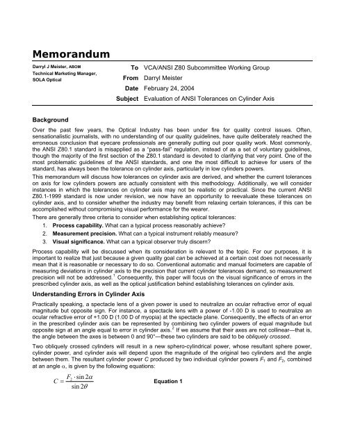
Memorandum<br />
<str<strong>on</strong>g>Darryl</str<strong>on</strong>g> J <str<strong>on</strong>g>Meister</str<strong>on</strong>g>, ABOM<br />
<str<strong>on</strong>g>Technical</str<strong>on</strong>g> Marketing Manager,<br />
SOLA Optical<br />
Background<br />
To VCA/ANSI Z80 Subcommittee Working Group<br />
From <str<strong>on</strong>g>Darryl</str<strong>on</strong>g> <str<strong>on</strong>g>Meister</str<strong>on</strong>g><br />
Date February 24, 2004<br />
Subject Evaluati<strong>on</strong> of ANSI Tolerances <strong>on</strong> <strong>Cyl</strong>inder <strong>Axis</strong><br />
Over the past few years, the Optical Industry has been under fire for quality c<strong>on</strong>trol issues. Often,<br />
sensati<strong>on</strong>alistic journalists, with no understanding of our quality guidelines, have quite deliberately reached the<br />
err<strong>on</strong>eous c<strong>on</strong>clusi<strong>on</strong> that eyecare professi<strong>on</strong>als are generally putting out poor quality work. Most comm<strong>on</strong>ly,<br />
the ANSI Z80.1 standard is misapplied as a “pass-fail” regulati<strong>on</strong>, instead of as a set of voluntary guidelines,<br />
though the majority of the first secti<strong>on</strong> of the Z80.1 standard is devoted to clarifying that very point. One of the<br />
most problematic guidelines of the ANSI standards, and <strong>on</strong>e the most difficult to achieve for users of the<br />
standard, has always been the tolerance <strong>on</strong> cylinder axis, particularly in low cylinders powers.<br />
This memorandum will discuss how tolerances <strong>on</strong> cylinder axis are derived, and whether the current tolerances<br />
<strong>on</strong> axis for low cylinders powers are actually c<strong>on</strong>sistent with this methodology. Additi<strong>on</strong>ally, we will c<strong>on</strong>sider<br />
instances in which the tolerances <strong>on</strong> cylinder axis may not be realistic or practical. Since the current ANSI<br />
Z80.1-1999 standard is now under revisi<strong>on</strong>, we now have an opportunity to reevaluate these tolerances <strong>on</strong><br />
cylinder axis, and to c<strong>on</strong>sider whether the industry may benefit from relaxing certain tolerances, if this can be<br />
accomplished without compromising visual performance for the wearer.<br />
There are generally three criteria to c<strong>on</strong>sider when establishing optical tolerances:<br />
1. Process capability. What can a typical process reas<strong>on</strong>ably achieve?<br />
2. Measurement precisi<strong>on</strong>. What can a typical instrument reliably measure?<br />
3. Visual significance. What can a typical observer truly discern?<br />
Process capability will be discussed when its c<strong>on</strong>siderati<strong>on</strong> is relevant to the topic. For our purposes, it is<br />
important to realize that just because a given quality goal can be achieved at a certain cost does not necessarily<br />
mean that it is reas<strong>on</strong>able or necessary to do so. C<strong>on</strong>venti<strong>on</strong>al automatic and manual focimeters are capable of<br />
measuring deviati<strong>on</strong>s in cylinder axis to the precisi<strong>on</strong> that current cylinder tolerances demand, so measurement<br />
precisi<strong>on</strong> will not be addressed. 1 C<strong>on</strong>sequently, this paper will focus <strong>on</strong> the visual significance of errors in the<br />
prescribed cylinder axis, as well as the optical justificati<strong>on</strong> behind establishing tolerances <strong>on</strong> cylinder axis.<br />
Understanding Errors in <strong>Cyl</strong>inder <strong>Axis</strong><br />
Practically speaking, a spectacle lens of a given power is used to neutralize an ocular refractive error of equal<br />
magnitude but opposite sign. For instance, a spectacle lens with a power of -1.00 D is used to neutralize an<br />
ocular refractive error of +1.00 D (1.00 D of myopia) at the spectacle plane. C<strong>on</strong>sequently, the effects of an error<br />
in the prescribed cylinder axis can be represented by combining two cylinder powers of equal magnitude but<br />
opposite sign at an angle equal to error in cylinder axis. 2 If we assume that their axes are not collinear—that is,<br />
the angle between the axes is between 0 and 90°—these two cylinders are said to be obliquely crossed.<br />
Two obliquely crossed cylinders will result in a new sphero-cylindrical power, whose resultant sphere power,<br />
cylinder power, and cylinder axis will depend up<strong>on</strong> the magnitude of the original two cylinders and the angle<br />
between them. The resultant cylinder power C produced by two individual cylinder powers F1 and F2, combined<br />
at an angle α, is given by the following equati<strong>on</strong>s:<br />
2 ⋅ sin 2α<br />
=<br />
sin 2θ<br />
F<br />
C Equati<strong>on</strong> 1
where θ is given by:<br />
F2<br />
⋅ sin 2α<br />
tan 2θ<br />
=<br />
F + F ⋅ cos2α<br />
1<br />
2<br />
Equati<strong>on</strong> 2<br />
Moreover, in our particular case—wherein the cylinder powers (F1 and F2) are equal in magnitude and opposite<br />
in sign—the equati<strong>on</strong>s can be simplified c<strong>on</strong>siderably. In this special case, the resultant cylinder power C<br />
produced by combining two cylinders powers of equal magnitude (F1), <strong>on</strong>e negative and <strong>on</strong>e positive, is given<br />
by: 3<br />
C = 2F1 ⋅sinα<br />
Equati<strong>on</strong> 3<br />
Equati<strong>on</strong> 3 is also the equati<strong>on</strong> for a Stokes Lens. This resultant cylinder power is essentially a residual<br />
refractive error produced by the misalignment of the cylinder axis of the spectacle lens with the prescribed axis.<br />
Furthermore, the mean power (or spherical equivalent) remains unchanged in this case, regardless of the<br />
original or resultant cylinder power. C<strong>on</strong>sequently, <strong>on</strong>ly the resultant cylinder power is meaningful.<br />
For instance, given a prescribed cylinder power of 2.00 D and an error in the prescribed cylinder axis of 5°, the<br />
resultant cylinder power error is:<br />
( 2.<br />
00)<br />
⋅sin5<br />
0.<br />
35<br />
C = 2 =<br />
C<strong>on</strong>sequently, an error from the prescribed axis of 5° produces a residual astigmatic (cylinder power) error of<br />
0.35 D. Therefore, the wearer acceptance of a sphero-cylindrical lens with an error in cylinder axis can be<br />
c<strong>on</strong>sidered in terms of its capacity to blur visi<strong>on</strong> as a normal power error would. In this example, the error in axis<br />
is essentially equal to an unwanted cylinder power error of 0.35 D.<br />
Establishing Tolerances <strong>on</strong> <strong>Cyl</strong>inder <strong>Axis</strong><br />
For the purposes of establishing prescripti<strong>on</strong> tolerances, we might ask how far the axis of a given cylinder power<br />
must be shifted in order to introduce an error in cylinder power equivalent to our normal (ANSI Z80.1) cylinder<br />
power tolerance. This would allow us to arrive at a reas<strong>on</strong>able baseline for establishing cylinder axis tolerances<br />
based up<strong>on</strong> the assumed visual significance of a comparable power tolerance, which has indeed been the<br />
historical approach to establishing cylinder axis tolerances. After rearranging the Equati<strong>on</strong> 3 to solve for the<br />
angle α, we have:<br />
= sin<br />
⎛ C ⎞<br />
⎜<br />
⎟<br />
⎝ 2F1<br />
⎠<br />
−1<br />
α Equati<strong>on</strong> 4<br />
Now, if we assume a tolerance in cylinder power of 0.13 D, which is the current Z80.1-1999 tolerance <strong>on</strong><br />
cylinder powers up to 2.00 D, we can solve the angle α as a functi<strong>on</strong> of cylinder power, as shown in Figure 1. 4<br />
Error in <strong>Cyl</strong>inder <strong>Axis</strong><br />
35<br />
30<br />
25<br />
20<br />
15<br />
10<br />
5<br />
0<br />
0.00<br />
<strong>Axis</strong> Error Required To Induce<br />
A 0.13 D <strong>Cyl</strong>inder Power Error<br />
0.25<br />
0.50<br />
0.75<br />
1.00<br />
1.25<br />
1.50<br />
1.75<br />
2.00<br />
2.25<br />
Prescribed <strong>Cyl</strong>inder Power<br />
Figure 1: Error in cylinder axis required to induce a 0.13 D cylinder power error<br />
2.50<br />
2.75<br />
3.00<br />
<strong>Page</strong> 2
For instance, we can see that a prescribed cylinder power of 1.00 D requires an error from its prescribed axis of<br />
nearly 4° in order to induce 0.13 D of unwanted cylinder power. It should be apparent from the figure that the<br />
results of the functi<strong>on</strong> become asymptotic for extreme cylinder powers. As the prescribed cylinder power<br />
approaches infinity, the error in axis required to induce the cylinder power tolerance approaches zero.<br />
Furthermore, as the prescribed cylinder power reaches its lowest limit (equal to <strong>on</strong>e-half the cylinder power<br />
tolerance), the required axis error reaches 90°.<br />
Fry cited a similar methodology for the establishment of axis tolerances with the ANSI Z80.1-1979 standard. 5<br />
Although Fry’s results were derived from different equati<strong>on</strong>s, they are in fact equivalent to the results produced<br />
by the simpler formula given by Equati<strong>on</strong> 4. However, Fry’s results were based up<strong>on</strong> a cylinder power tolerance<br />
of 0.12 D, instead of the current tolerance of 0.13 D. For the sake of comparis<strong>on</strong>, Table 1 shows the errors in<br />
cylinder axis necessary to induce both a 0.12 D error in cylinder power (used by Fry) and a 0.13 D error in<br />
cylinder power (the current ANSI Z80.1-1999 tolerance). The current ANSI Z80.1-1999 tolerances <strong>on</strong> cylinder<br />
axis have also been included.<br />
Table 1: Error in cylinder axis required to induce 0.12 and 0.13 D cylinder power errors<br />
<strong>Cyl</strong>inder Power 0.25 0.50 0.75 1.00 1.25 1.50 1.75 2.00 2.25 2.50 2.75 3.00<br />
<strong>Axis</strong> Error @ 0.12 D 13.9° 6.9° 4.6° 3.4° 2.8° 2.3° 2.0° 1.7° 1.5° 1.4° 1.3° 1.1°<br />
<strong>Axis</strong> Error @ 0.13 D 15.1° 7.5° 5.0° 3.7° 3.0° 2.5° 2.1° 1.9° 1.7° 1.5° 1.4° 1.2°<br />
Z80.1 Tolerance 7.0° 5.0° 5.0° 3.0° 3.0° 3.0° 2.0° 2.0° 2.0° 20.° 2.0° 2.0°<br />
As previously stated, these tolerances were based in no small part <strong>on</strong> Fry’s methodology. We can draw some<br />
interesting c<strong>on</strong>clusi<strong>on</strong>s from this table. While the tolerance <strong>on</strong> cylinder power was loosened slightly in<br />
subsequent revisi<strong>on</strong>s of the Z80.1 standard, the tolerances <strong>on</strong> cylinder axis were not adjusted accordingly.<br />
Furthermore, the axis tolerances for the 0.25 and 0.50 D cylinder powers are not c<strong>on</strong>sistent with the results<br />
obtained using either the 0.12 D or the 0.13 D cylinder power tolerance in Equati<strong>on</strong> 4. Note that the tolerance for<br />
0.25 D of prescribed cylinder power, in particular, is c<strong>on</strong>siderably tighter than necessary.<br />
Also note that the minimum tolerance is 2° for high cylinder powers, though the results actually demand slightly<br />
tighter values. In terms of mechanical alignment, it is generally assumed throughout the ANSI Z80.1-1999<br />
standard that a tolerance of 2° is reas<strong>on</strong>able for errors in angular alignment (e.g., segment tilt). C<strong>on</strong>sequently,<br />
while there may be optical justificati<strong>on</strong> for a tighter tolerance in higher cylinder powers, the tolerance has been<br />
intenti<strong>on</strong>ally limited out of an assumpti<strong>on</strong> of reas<strong>on</strong>able process capabilities.<br />
Blur Produced by Unwanted <strong>Cyl</strong>inder Power<br />
There is a single locati<strong>on</strong>, lying at the dioptric midpoint of the two focal lines that bound Sturm’s interval in an<br />
astigmatic focus, where the bundle of rays produces a circular cross-secti<strong>on</strong>. This locati<strong>on</strong> is referred to as the<br />
circle of least c<strong>on</strong>fusi<strong>on</strong>. As stated earlier, the resultant cylinder power error produced by a misalignment in<br />
cylinder axis represents a purely astigmatic error, as shown in Figure 2. That is, the error from the mean sphere<br />
power (or spherical equivalent) remains equal to zero. In this case, the circle of least c<strong>on</strong>fusi<strong>on</strong> of the astigmatic<br />
bundle will fall up<strong>on</strong> the retina, no matter how far the cylinder axis is off from the prescribed axis.<br />
Point<br />
object<br />
Sphere<br />
focus<br />
Figure 2. Circle of least c<strong>on</strong>fusi<strong>on</strong> produced by an astigmatic focus<br />
Circle of<br />
least c<strong>on</strong>fusi<strong>on</strong><br />
<strong>Cyl</strong>inder<br />
focus<br />
<strong>Page</strong> 3
The circle of least c<strong>on</strong>fusi<strong>on</strong> is proporti<strong>on</strong>al to both the pupil size and power error. As the size of the circle<br />
increases, so do the diffusi<strong>on</strong> of visual informati<strong>on</strong> and the percepti<strong>on</strong> of blur by the wearer. Moreover, the<br />
circular patch of “blur” produced by the resultant cylinder power error at the circle of least c<strong>on</strong>fusi<strong>on</strong> is half the<br />
size of the circular patch of blur produced by a spherical error of equal magnitude. C<strong>on</strong>sequently, a given<br />
dioptric error in cylinder power produces half as much blur as an equal dioptric error in sphere power. 6<br />
For instance, recall that an error from the prescribed axis of 5° for a cylinder power of 2.00 D produces a<br />
residual astigmatic (cylinder power) error of 0.35 D. The blur produced by this cylinder error is comparable to the<br />
blur produced by a 0.35 / 2 = 0.175 D error in mean sphere power.<br />
At this point, it might be reas<strong>on</strong>able to ask why the ANSI Z80.1-1999 tolerance <strong>on</strong> cylinder power is comparable<br />
to the tolerance <strong>on</strong> sphere power if its effects up<strong>on</strong> visi<strong>on</strong> are less significant? There are several factors to<br />
c<strong>on</strong>sider. Firstly, power tolerances are generally based up<strong>on</strong> <strong>on</strong>e-half the smallest increment of measurement<br />
used during ocular refracti<strong>on</strong>. <strong>Cyl</strong>inder power is generally prescribed in 0.25-diopter increments, so a tolerance<br />
of roughly 0.25 / 2 = 0.125 D makes sense from a practical and metrological standpoint.<br />
Sec<strong>on</strong>dly, the tolerance <strong>on</strong> sphere power doesn’t actually apply to the mean sphere power (or spherical<br />
equivalent) of the prescripti<strong>on</strong>, but rather the power through <strong>on</strong>e principal meridian. For a cylinder power<br />
tolerance of 0.13 D and a sphere power tolerance of 0.12 D, the error in mean sphere power can reach up to<br />
0.13 / 2 + 0.12 = 0.185 D, or the sum of the sphere power tolerance and half the cylinder power tolerance.<br />
C<strong>on</strong>sequently, higher cylinder power tolerances effectively increase the sphere power tolerance.<br />
Lastly, the additive nature of the tolerances <strong>on</strong> cylinder must also be c<strong>on</strong>sidered, since errors in cylinder axis<br />
and cylinder power are both allowed. If the tolerance <strong>on</strong> cylinder axis allows up to 0.12 or 0.13 D of induced<br />
cylinder power, this will compound any error in the actual cylinder power, itself.<br />
Low <strong>Cyl</strong>inder Powers and Progressive Additi<strong>on</strong> Lenses<br />
One of the most problematic aspects of cylinder tolerances is the c<strong>on</strong>trol of cylinder axis in extremely low<br />
cylinder powers. In particular, progressive additi<strong>on</strong> lenses, which often have small amounts of cylinder power as<br />
a result of the surface astigmatism <strong>on</strong> the progressive surface, are susceptible to this problem. Laboratory<br />
technicians often find it difficult to achieve the desired prescripti<strong>on</strong> in low cylinder powers when processing<br />
progressive lenses.<br />
Due to the highly aspheric nature of progressive surfaces, the techniques used to manufacture the molds, and<br />
the variati<strong>on</strong>s produced during the manufacturing process, it is not unlikely for a progressive lens surface to<br />
have a small amount of unwanted surface astigmatism at the distance reference point—directly from the<br />
manufacturer. Progressive lens surfaces are highly aspheric and have a great deal of surface astigmatism, as a<br />
c<strong>on</strong>sequence of providing a progressive change in add power. This surface astigmatism results in unwanted<br />
cylinder power.<br />
Even though the near and distance reference points of a progressive lens may produce no unwanted cylinder<br />
power in the initial lens design, manufacturing factors—such as lens material shrinkage—can create variati<strong>on</strong>s<br />
in the surface powers of the lens blank. Moreover, the apertures of many focimeters can “pick up” some of the<br />
unwanted cylinder power surrounding the reference points of the lens. Finally, some modern progressive lenses<br />
may have a small amount of cylinder power intenti<strong>on</strong>ally engineered into lens design at the distance and/or near<br />
measurement points in order to compensate for the effects of lens tilt and the positi<strong>on</strong> of wear <strong>on</strong> the power of<br />
the lens as perceived by the actual wearer. This is referred to as as-worn optimizati<strong>on</strong>.<br />
Because of the difficulties inherent in the producti<strong>on</strong> and measurement of progressive lenses, the Internati<strong>on</strong>al<br />
Standards Organizati<strong>on</strong> has established looser surface power tolerances for progressive additi<strong>on</strong> lens blanks<br />
(ISO 10322-2). 7 ISO tolerances allow 0.09 D of unwanted surface astigmatism in the distance z<strong>on</strong>e of most<br />
progressive lens blanks, which is over two times what ISO tolerances allow for c<strong>on</strong>venti<strong>on</strong>al bifocals. The<br />
unwanted cylinder power produced by this surface astigmatism interacts with any prescribed cylinder power <strong>on</strong><br />
the back surface of the lens, resulting in a crossed cylinder effect, which can be computed using the<br />
mathematics described earlier (Equati<strong>on</strong>s 1 and 2).<br />
<strong>Cyl</strong>inder power <strong>on</strong> a lens surface, which has occurred either because of engineering, manufacturing, processing<br />
or measuring, will interact optically with any prescribed cylinder power. A c<strong>on</strong>sequence of this effect is a change<br />
in the axis of the prescribed cylinder power, particularly in weak cylinders. When <strong>on</strong>e cylinder power is<br />
c<strong>on</strong>siderably str<strong>on</strong>ger than the other, the resultant axis will shift very little from the axis of the str<strong>on</strong>ger cylinder.<br />
C<strong>on</strong>sequently, progressive lenses with a small amount of unwanted cylinder power in the distance z<strong>on</strong>e will<br />
generally have very little effect up<strong>on</strong> str<strong>on</strong>ger prescribed cylinder powers.<br />
<strong>Page</strong> 4
However, when both cylinders are comparable to each other, the resultant axis will shift closer to the midpoint<br />
between them. Figure 3 dem<strong>on</strong>strates that combining a cylinder of -0.09 D × 045, equal to ISO’s tolerance for<br />
unwanted astigmatism in progressive lenses, with a prescribed cylinder of -0.25 D × 180 results in a new<br />
cylinder of -0.26 D × 010. This is 3° outside of the ANSI Z80.1—1999 tolerance. C<strong>on</strong>sequently, it is possible for<br />
a precisely surfaced lens to meet the ISO standard while failing the ANSI standard.<br />
Prescribed<br />
Resultant Resultant<br />
Unwanted Unwanted<br />
0.09 0.09 × × 045 045<br />
0.26 0.26 × × 010 010<br />
0.25 × 180<br />
Figure 3. Resultant cylinder power produced by a small amount of unwanted cylinder power<br />
Fortunately, the small amount of unwanted cylinder power measured in the distance or near z<strong>on</strong>e of a properly<br />
manufactured progressive lens is generally visually inc<strong>on</strong>sequential to the wearer. Moreover, producing a<br />
progressive lens that appears to be virtually free from unwanted astigmatism at the distance reference point<br />
when measured across the range of focimeters currently in use would be both unnecessary and needlessly<br />
costly to progressive lens customers. In progressive lens designs with as-worn optimizati<strong>on</strong>, it may even<br />
represent a compromise in visual performance for the wearer.<br />
ANSI Compliance Study<br />
In 1999, the OLA and VCA jointly sp<strong>on</strong>sored a study to investigate the compliance to the ANSI Z80.1 standard<br />
by wholesale optical laboratories in order to determine whether the ANSI tolerances were realistic and<br />
representative of the current state-of-the-art of the industry. Roughly 800 prescripti<strong>on</strong> lenses (or 400 pairs) were<br />
evaluated and, of those, 600 c<strong>on</strong>tained prescribed cylinder power. These lenses were prescripti<strong>on</strong> “jobs” that<br />
were released by the laboratories to their customers after they were evaluated.<br />
If the next revisi<strong>on</strong> of the ANSI Z80.1 standard returns to the use of the sphere power tolerance, as opposed to<br />
the use of the meridian of highest power tolerance—which is <strong>on</strong>e of the last vestigial remains from the ISOinspired<br />
ANSI Z80.1-1995 standard, the highest failure rate in meeting power tolerances for these 800 lenses<br />
occurs with cylinder axis. Applying the current ANSI Z80.1-1999 tolerances <strong>on</strong> cylinder axis to the 600 lenses<br />
with prescribed cylinder power results in a failure rate of approximately 9.3%, as shown in Figure 4.<br />
Number of Failures<br />
10<br />
8<br />
6<br />
4<br />
2<br />
0<br />
<strong>Cyl</strong>inder <strong>Axis</strong> Failures: Z80.1-1999<br />
0.25<br />
0.50<br />
0.75<br />
1.00<br />
1.25<br />
1.50<br />
1.75<br />
2.00<br />
<strong>Cyl</strong>inder Power<br />
Figure 4. Distributi<strong>on</strong> of cylinder axis failures by cylinder power using ANSI Z80.1—1999<br />
2.25<br />
2.50<br />
2.75<br />
3.00<br />
<strong>Page</strong> 5
Now, what if we evaluate these data using more reas<strong>on</strong>able criteria for the lower cylinder powers? Choosing<br />
axis tolerances for the 0.25 and 0.50 D cylinder powers that were more in line with the methodology used to<br />
derive the tolerances for the other cylinder powers would improve our failure rate c<strong>on</strong>siderably.<br />
For instance, if we were to increase the axis tolerance <strong>on</strong> cylinder powers of 0.25 D to a more reas<strong>on</strong>able 9°<br />
and the tolerance <strong>on</strong> cylinder powers of 0.50 D to a more reas<strong>on</strong>able 7°, the failure rate drops to roughly 7.7%,<br />
as shown in Figure 5. This represents an 18% reducti<strong>on</strong> in failures.<br />
Number of Failures<br />
10<br />
8<br />
6<br />
4<br />
2<br />
0<br />
<strong>Cyl</strong>inder <strong>Axis</strong> Failures: Proposed<br />
0.25<br />
0.50<br />
0.75<br />
1.00<br />
1.25<br />
1.50<br />
1.75<br />
2.00<br />
<strong>Cyl</strong>inder Power<br />
Figure 5. Distributi<strong>on</strong> of cylinder axis failures by cylinder power using proposed tolerances<br />
Moreover, these slightly relaxed tolerances are quite reas<strong>on</strong>able and justifiable, and are actually more<br />
c<strong>on</strong>sistent with the optical criteria used to establish the other axis tolerances. Note that increasing the tolerance<br />
<strong>on</strong> cylinder axis for a prescribed cylinder power of 0.25 D even further, from 9° to something even more<br />
realistic—such as 11°, will result in <strong>on</strong>ly marginal improvements in the failure rate. In summary, we can literally<br />
“improve” the tolerances <strong>on</strong> cylinder axis by using a more c<strong>on</strong>sistent methodology while dramatically reducing<br />
industry reject rates. C<strong>on</strong>sequently, it would behoove the Z80 Subcommittee to c<strong>on</strong>sider relaxing the tolerances<br />
<strong>on</strong> cylinder axis for the 0.25 and 0.50 D cylinder powers accordingly.<br />
1<br />
Fry, GA. “Tolerance for the <strong>Cyl</strong>inder <strong>Axis</strong>.” Optical Index. March 17, 1977. Pg. 20<br />
2 nd<br />
Bennett, AG & Rabbetts, RB. Clinical Visual Optics, 2 Ed. L<strong>on</strong>d<strong>on</strong>: Butterworths, 1989. Pg. 87<br />
3<br />
Tunnacliffe, AH & Hirst, JG. Optics. L<strong>on</strong>d<strong>on</strong>: Associati<strong>on</strong> of British Dispensing Opticians, 1996. Pg. 93<br />
4<br />
ANSI Z80.1-1999. Prescripti<strong>on</strong> Ophthalmic Lenses – Recommendati<strong>on</strong>s. American Nati<strong>on</strong>al Standards<br />
Institute<br />
5<br />
Fry, GA. Pg. 22<br />
6<br />
Bennett, AG & Rabbetts, RB. Pg. 85<br />
7<br />
ISO 10322-2: 1996. Ophthalmic optics – Semi-finished spectacle lens blanks – Part 2: Specificati<strong>on</strong>s for<br />
progressive power lens blanks. Internati<strong>on</strong>al Standards Organizati<strong>on</strong><br />
2.25<br />
2.50<br />
2.75<br />
3.00<br />
<strong>Page</strong> 6