Flexitallic Spiral Wound Gasket Info - AFT Fasteners
Flexitallic Spiral Wound Gasket Info - AFT Fasteners
Flexitallic Spiral Wound Gasket Info - AFT Fasteners

You also want an ePaper? Increase the reach of your titles
YUMPU automatically turns print PDFs into web optimized ePapers that Google loves.
TABLE<br />
20 NOMINAL<br />
DIAMETER<br />
BOLT<br />
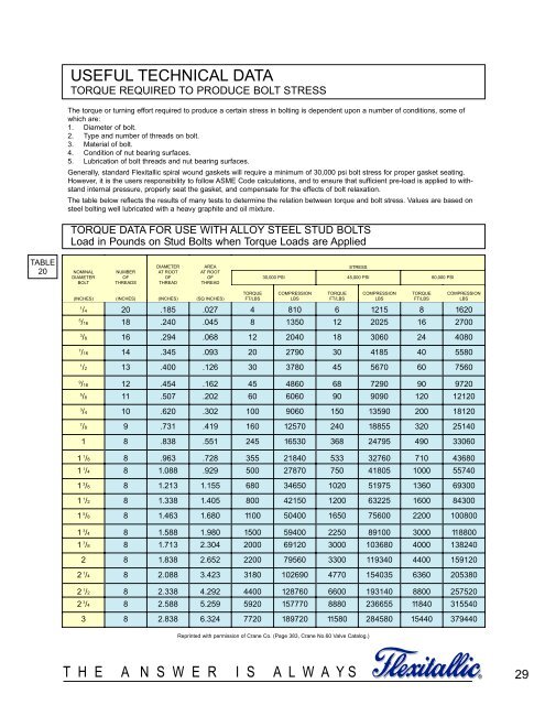
USEFUL TECHNICAL DATA<br />
TORQUE REQUIRED TO PRODUCE BOLT STRESS<br />
The torque or turning effort required to produce a certain stress in bolting is dependent upon a number of conditions, some of<br />
which are:<br />
1. Diameter of bolt.<br />
2. Type and number of threads on bolt.<br />
3. Material of bolt.<br />
4. Condition of nut bearing surfaces.<br />
5. Lubrication of bolt threads and nut bearing surfaces.<br />
Generally, standard <strong>Flexitallic</strong> spiral wound gaskets will require a minimum of 30,000 psi bolt stress for proper gasket seating.<br />
However, it is the users responsibility to follow ASME Code calculations, and to ensure that sufficient pre-load is applied to withstand<br />
internal pressure, properly seat the gasket, and compensate for the effects of bolt relaxation.<br />
The table below reflects the results of many tests to determine the relation between torque and bolt stress. Values are based on<br />
steel bolting well lubricated with a heavy graphite and oil mixture.<br />
TORQUE DATA FOR USE WITH ALLOY STEEL STUD BOLTS<br />
Load in Pounds on Stud Bolts when Torque Loads are Applied<br />
(INCHES)<br />
NUMBER<br />
OF<br />
THREADS<br />
(INCHES)<br />
DIAMETER<br />
DIAMETER AT ROOT<br />
AT ROOT OF<br />
OF THREAD THREAD<br />
(INCHES)<br />
AREA<br />
ATAREA ROOT<br />
AT ROOT OF<br />
OF THREAD THREAD<br />
(SQ. (SQ INCHES)<br />
TORQUE<br />
FT/LBS<br />
T H E A N S W E R I S A L W A Y S<br />
STRESS<br />
30,000 PSI 45,000 PSI 60,000 PSI<br />
COMPRESSION<br />
LBS. LBS<br />
TORQUE<br />
FT/LBS<br />
COMPRESSION<br />
LBS. LBS<br />
TORQUE<br />
FT/LBS<br />
COMPRESSION<br />
LBS. LBS<br />
1 /4 20 .185 .027 4 810 6 1215 8 1620<br />
5 /16 18 .240 .045 8 1350 12 2025 16 2700<br />
3 /8 16 .294 .068 12 2040 18 3060 24 4080<br />
7 /16 14 .345 .093 20 2790 30 4185 40 5580<br />
1 /2 13 .400 .126 30 3780 45 5670 60 7560<br />
9 /16 12 .454 .162 45 4860 68 7290 90 9720<br />
5 /8 11 .507 .202 60 6060 90 9090 120 12120<br />
3 /4 10 .620 .302 100 9060 150 13590 200 18120<br />
7 /8 9 .731 .419 160 12570 240 18855 320 25140<br />
1 8 .838 .551 245 16530 368 24795 490 33060<br />
1 1 /8 8 .963 .728 355 21840 533 32760 710 43680<br />
1 1 /4 8 1.088 .929 500 27870 750 41805 1000 55740<br />
1 3 /8 8 1.213 1.155 680 34650 1020 51975 1360 69300<br />
1 1 /2 8 1.338 1.405 800 42150 1200 63225 1600 84300<br />
1 5 /8 8 1.463 1.680 1100 50400 1650 75600 2200 100800<br />
1 3 /4 8 1.588 1.980 1500 59400 2250 89100 3000 118800<br />
1 7 /8 8 1.713 2.304 2000 69120 3000 103680 4000 138240<br />
2 8 1.838 2.652 2200 79560 3300 119340 4400 159120<br />
2 1 /4 8 2.088 3.423 3180 102690 4770 154035 6360 205380<br />
2 1 /2 8 2.338 4.292 4400 128760 6600 193140 8800 257520<br />
2 3 /4 8 2.588 5.259 5920 157770 8880 236655 11840 315540<br />
3 8 2.838 6.324 7720 189720 11580 284580 15440 379440<br />
Reprinted with permission of Crane Co. (Page 383, Crane No.60 Valve Catalog.)<br />
®<br />
29