Flexitallic Spiral Wound Gasket Info - AFT Fasteners
Flexitallic Spiral Wound Gasket Info - AFT Fasteners
Flexitallic Spiral Wound Gasket Info - AFT Fasteners

You also want an ePaper? Increase the reach of your titles
YUMPU automatically turns print PDFs into web optimized ePapers that Google loves.
TABLE<br />
23<br />
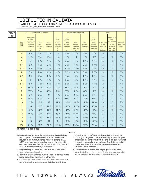
USEFUL TECHNICAL DATA<br />
FACING DIMENSIONS FOR ASME B16.5 & BS 1560 FLANGES<br />
CLASS 150, 300, 400, 600, 900, 1500 AND 2500<br />
NOM<br />
PIPE<br />
SIZE<br />
RAISED FACE,<br />
LAPPED,<br />
LARGE MALE,<br />
& LARGE<br />
TONGUES<br />
See Note 5<br />
1 /2 1 3 /8<br />
3 /4 1 11 /16<br />
22 /32 1 3 /8 1 1 7 /16<br />
25 /32 1 7 /16<br />
T H E A N S W E R I S A L W A Y S<br />
15 /16<br />
15 /16 1 11 /16 1 5 /16 1 3 /4 1 1 3 /4 1 1 /4<br />
1 2 1 3 /16 1 7 /8 1 1 /2 2 1 /16 1 1 /4 1 15 /16 1 7 /16<br />
1 1 /4 2 1 /2 1 1 /2 2 1 /4 1 7 /8 2 9 /16 1 9 /16 2 5 /16 1 13 /16<br />
1 1 /2 2 7 /8 1 3 /4 2 1 /2 2 1 /8 2 15 /16 1 13 /16 2 9 /16 2 1 /16<br />
2 3 5 /8 2 1 /4 3 1 /4 2 7 /8 3 11 /16 2 5 /16 3 5 /16 2 13 /16<br />
2 1 /2 4 1 /8 2 11 /16 3 3 /4 3 3 /8 4 3 /16 2 3 /4 3 13 /16 3 5 /16<br />
3 5 3 5 /16 4 5 /8 4 1 /4 5 1 /16 3 3 /8 4 11 /16 4 3 /16<br />
3 1 /2 5 1 /2 3 13 /16 5 1 /8 4 3 /4 5 9 /16 3 7 /8 5 3 /16 4 11 /16<br />
4 6 3 /16 4 5 /16 5 11 /16 5 3 /16 6 1 /4 4 3 /8 5 3 /4 5 1 /8<br />
5 7 5 /16 5 3 /8 6 13 /16 6 5 /16 7 3 /8 5 7 /16 6 7 /8 6 1 /4<br />
6 8 1 /2 6 3 /8 8 7 1 /2 8 9 /16 6 7 /16 8 1 /16 7 7 /16<br />
8 10 5 /8 8 3 /8 10 9 3 /8 10 11 /16 8 7 /16 10 1 /16 9 5 /16<br />
10 12 3 /4 10 1 /2 12 11 1 /4 12 13 /16 10 9 /16 12 1 /16 11 3 /16<br />
12 15 12 1 /2 14 1 /4 13 1 /2 15 1 /16 12 9 /16 14 5 /16 13 7 /16<br />
14 16 1 /4 13 3 /4 15 1 /2 14 3 /4 16 5 /16 13 13 /16 15 9 /16 14 11 /16<br />
16 18 1 /2 15 3 /4 17 5 /8 16 3 /4 18 9 /16 15 13 /16 17 11 /16 16 11 /16<br />
18 21 17 3 /4 20 1 /8 19 1 /4 21 1 /16 17 13 /16 20 3 /16 19 3 /16<br />
20 23 19 3 /4 22 21 23 1 /16 19 13 /16 22 1 /16 20 15 /16<br />
24 27 1 /4 23 3 /4 26 1 /4 25 1 /4 27 5 /16 23 13 /16 26 5 /16 25 3 /16<br />
DIMENSIONS IN INCHES<br />
R<br />
OUTSIDE DIAMETER See Note 3 OUTSIDE DIAMETER See Note 3 HEIGHT<br />
SMALL<br />
MALE<br />
See Notes<br />
4&5<br />
S<br />
SMALL<br />
TONGUE<br />
See Note 5<br />
T<br />
I.D. OF<br />
LARGE<br />
& SMALL<br />
TONGUE<br />
See Notes<br />
3 & 5<br />
LARGE<br />
FEMALE &<br />
LARGE<br />
GROOVE<br />
See Note 5<br />
1. Regular facing far class 150 and 300 steel flanged fittings<br />
and companion flange standards is a 1/16” raised face<br />
included in the minimum flange thickness dimensions. A<br />
1/16” raised face may be supplied also on the class 400,<br />
600, 900, 1500, and 2500 flange standards, but it must be<br />
added to the minimum flange thickness.<br />
2. Regular facing for class 400, 600, 900, 1500, and 2500<br />
flange thickness dimensions.<br />
3. Tolerance of plus or minus 0.016 in. (1/64”) is allowed on the<br />
inside and outside diameters of all facings.<br />
4. For small male and female joints care should be taken in the<br />
use of these dimensions to insure that pipe used is thick<br />
U<br />
w<br />
SMALL<br />
FEMALE<br />
See Note 4<br />
See Note 5<br />
X<br />
SMALL<br />
GROOVE<br />
See Note 5<br />
V<br />
I.D. OF<br />
LARGE &<br />
SMALL<br />
GROOVE<br />
See Note 3<br />
See Note 5<br />
Z<br />
RAISED FACE<br />
CLASS<br />
150 & 300<br />
See Note 1<br />
1 /16<br />
1 /16<br />
1 /16<br />
1 /16<br />
1 /16<br />
1 /16<br />
1 /16<br />
1 /16<br />
1 /16<br />
1 /16<br />
1 /16<br />
1 /16<br />
1 /16<br />
1 /16<br />
1 /16<br />
1 /16<br />
1 /16<br />
1 /16<br />
1 /16<br />
1 /16<br />
RAISED FACE<br />
LARGE &<br />
SMALL MALE<br />
& TONGUE<br />
CLASS<br />
400, 600, 900<br />
1500 & 2500<br />
See Note 2<br />
1 /4<br />
1 /4<br />
1 /4<br />
1 /4<br />
1 /4<br />
1 /4<br />
1 /4<br />
1 /4<br />
1 /4<br />
1 /4<br />
1 /4<br />
1 /4<br />
1 /4<br />
1 /4<br />
1 /4<br />
1 /4<br />
1 /4<br />
1 /4<br />
1 /4<br />
1 /4<br />
DEPTH OF<br />
GROOVE OR<br />
FEMALE<br />
NOTES<br />
enough to permit sufficient bearing surface to prevent the<br />
crushing of the gasket. The dimensions apply particularly on<br />
lines where the joint is made on the end of the pipe. Screwed<br />
companion flanges for small male and female joints are furnished<br />
with plain face and are threaded with American<br />
Standard Locknut Thread.<br />
5. <strong>Gasket</strong>s for male-female and tongue-groove joints shall<br />
cover the bottom of the recess with minimum clearances taking<br />
into account the tolerances prescribed in Note 3.<br />
3 /16<br />
3 /16<br />
3 /16<br />
3 /16<br />
3 /16<br />
3 /16<br />
3 /16<br />
3 /16<br />
3 /16<br />
3 /16<br />
3 /16<br />
3 /16<br />
3 /16<br />
3 /16<br />
3 /16<br />
3 /16<br />
3 /16<br />
3 /16<br />
3 /16<br />
3 /16<br />
®<br />
31