Hollow fiber membrane life in membrane bioreactors (MBR) - GE ...
Hollow fiber membrane life in membrane bioreactors (MBR) - GE ...
Hollow fiber membrane life in membrane bioreactors (MBR) - GE ...

Create successful ePaper yourself
Turn your PDF publications into a flip-book with our unique Google optimized e-Paper software.
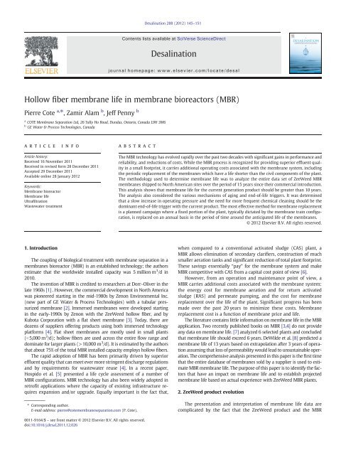
<strong>Hollow</strong> <strong>fiber</strong> <strong>membrane</strong> <strong>life</strong> <strong>in</strong> <strong>membrane</strong> <strong>bioreactors</strong> (<strong>MBR</strong>)<br />
Pierre Cote a, ⁎, Zamir Alam b , Jeff Penny b<br />
a COTE Membrane Separation Ltd, 26 Tally Ho Road, Dundas, Ontario, Canada L9H 3M6<br />
b <strong>GE</strong> Water & Process Technologies, Canada<br />
article <strong>in</strong>fo<br />
Article history:<br />
Received 16 November 2011<br />
Received <strong>in</strong> revised form 28 December 2011<br />
Accepted 29 December 2011<br />
Available onl<strong>in</strong>e 28 January 2012<br />
Keywords:<br />
Membrane bioreactor<br />
Membrane <strong>life</strong><br />
Ultrafiltration<br />
Wastewater treatment<br />
1. Introduction<br />
abstract<br />
The coupl<strong>in</strong>g of biological treatment with <strong>membrane</strong> separation <strong>in</strong> a<br />
<strong>membrane</strong>s bioreactor (<strong>MBR</strong>) is an established technology; the authors<br />
estimate that the worldwide <strong>in</strong>stalled capacity was 5 million m 3 /d <strong>in</strong><br />
2010.<br />
The <strong>in</strong>vention of <strong>MBR</strong> is credited to researchers at Dorr–Oliver <strong>in</strong> the<br />
late 1960s [1] . However, the commercial development <strong>in</strong> North America<br />
was pioneered start<strong>in</strong>g <strong>in</strong> the mid-1980s by Zenon Environmental Inc.<br />
(now part of <strong>GE</strong> Water & Process Technologies) with a tubular pressurized<br />
<strong>membrane</strong> [2]. Immersed <strong>membrane</strong>s were developed start<strong>in</strong>g<br />
<strong>in</strong> the early-1990s by Zenon with the ZeeWeed hollow <strong>fiber</strong>, and by<br />
Kubota Corporation with a flat sheet <strong>membrane</strong> [3]. Today,thereare<br />
dozens of suppliers offer<strong>in</strong>g products us<strong>in</strong>g both immersed technology<br />
platforms [4]. Flat sheet <strong>membrane</strong>s are mostly used <strong>in</strong> small plants<br />
(b5,000 m 3 /d); hollow <strong>fiber</strong>s are used across the entire flow range and<br />
dom<strong>in</strong>ate for larger plants (>10,000 m 3 /d). It is estimated by the authors<br />
that about 75% of the total <strong>MBR</strong> <strong>in</strong>stalled capacity employs hollow <strong>fiber</strong>s.<br />
The rapid adoption of <strong>MBR</strong> has been primarily driven by superior<br />
effluent quality that can meet ever more str<strong>in</strong>gent discharge regulations<br />
and by requirements for wastewater reuse [4]. In a recent paper,<br />
Hospido et al. [5] presented a <strong>life</strong> cycle assessment of a number of<br />
<strong>MBR</strong> configurations. <strong>MBR</strong> technology has also been widely adopted <strong>in</strong><br />
retrofit applications where the capacity of exist<strong>in</strong>g <strong>in</strong>frastructure requires<br />
expansion and/or upgrade. Equally important is the fact that,<br />
⁎ Correspond<strong>in</strong>g author.<br />
E-mail address: pierre@cote<strong>membrane</strong>separation.com (P. Cote).<br />
0011-9164/$ – see front matter © 2012 Elsevier B.V. All rights reserved.<br />
doi:10.1016/j.desal.2011.12.026<br />
Desal<strong>in</strong>ation 288 (2012) 145–151<br />
Contents lists available at SciVerse ScienceDirect<br />
Desal<strong>in</strong>ation<br />
journal homepage: www.elsevier.com/locate/desal<br />
The <strong>MBR</strong> technology has evolved rapidly over the past two decades with significant ga<strong>in</strong>s <strong>in</strong> performance and<br />
reliability, and reductions of costs. While the <strong>MBR</strong> process is recognized for provid<strong>in</strong>g superior effluent quality<br />
<strong>in</strong> a small footpr<strong>in</strong>t, it carries additional operat<strong>in</strong>g costs associated with the <strong>membrane</strong> system, <strong>in</strong>clud<strong>in</strong>g<br />
the periodic replacement of the <strong>membrane</strong>s which have a <strong>life</strong> shorter than the civil components of the plant.<br />
The methodology used to determ<strong>in</strong>e <strong>membrane</strong> <strong>life</strong> was to analyze the entire data set of ZeeWeed <strong>MBR</strong><br />
<strong>membrane</strong>s shipped to North American sites over the period of 15 years s<strong>in</strong>ce their commercial <strong>in</strong>troduction.<br />
This analysis shows that <strong>membrane</strong> <strong>life</strong> for the current generation product should be greater than 10 years.<br />
The analysis also considered the various mechanisms of ag<strong>in</strong>g and end-of-<strong>life</strong> triggers. It was determ<strong>in</strong>ed<br />
that a slow <strong>in</strong>crease <strong>in</strong> operat<strong>in</strong>g pressure and the need for more frequent chemical clean<strong>in</strong>g should be the<br />
dom<strong>in</strong>ant end-of-<strong>life</strong> trigger with the current product. The most effective method for <strong>membrane</strong> replacement<br />
is a planned campaign where a fixed portion of the plant, typically dictated by the <strong>membrane</strong> tra<strong>in</strong> configuration,<br />
is replaced on an annual basis <strong>in</strong> the period of time around the anticipated <strong>life</strong> of the <strong>membrane</strong>s.<br />
© 2012 Elsevier B.V. All rights reserved.<br />
when compared to a conventional activated sludge (CAS) plant, a<br />
<strong>MBR</strong> allows elim<strong>in</strong>ation of secondary clarifiers, construction of much<br />
smaller aeration tanks and significant reduction of total plant footpr<strong>in</strong>t.<br />
These sav<strong>in</strong>gs essentially “pay” for the <strong>membrane</strong> system and make<br />
<strong>MBR</strong> competitive with CAS from a capital cost po<strong>in</strong>t of view [6].<br />
However, from an operation and ma<strong>in</strong>tenance po<strong>in</strong>t of view, a<br />
<strong>MBR</strong> carries additional costs associated with the <strong>membrane</strong> system:<br />
the energy cost for <strong>membrane</strong> aeration and for return activated<br />
sludge (RAS) and permeate pump<strong>in</strong>g, and the cost for <strong>membrane</strong><br />
replacement over the <strong>life</strong> of the plant. Significant progress has been<br />
made over the past 20 years to m<strong>in</strong>imize these costs. Membrane<br />
replacement cost is a function of <strong>membrane</strong> price and <strong>life</strong>.<br />
The literature conta<strong>in</strong>s little <strong>in</strong>formation on <strong>membrane</strong> <strong>life</strong> <strong>in</strong> the <strong>MBR</strong><br />
application. Two recently published books on <strong>MBR</strong> [3,4] do not provide<br />
any data on <strong>membrane</strong> <strong>life</strong>. [7] analyzed 6 selected plants and concluded<br />
that <strong>membrane</strong> <strong>life</strong> should exceed 6 years. DeWilde et al. [8] predicted a<br />
<strong>membrane</strong> <strong>life</strong> of 13 years based on extrapolation after 3 years of operation<br />
assum<strong>in</strong>g that loss of permeability would lead to unsusta<strong>in</strong>able operation.<br />
The comprehensive analysis presented <strong>in</strong> this paper is the first time<br />
that the entire database of <strong>membrane</strong>s sold by a supplier is used to estimate<br />
<strong>MBR</strong> <strong>membrane</strong> <strong>life</strong>. The purpose of this paper is to identify the factors<br />
that have an impact on <strong>membrane</strong> <strong>life</strong> and to establish projected<br />
<strong>membrane</strong> <strong>life</strong> based on actual experience with ZeeWeed <strong>MBR</strong> plants.<br />
2. ZeeWeed product evolution<br />
The presentation and <strong>in</strong>terpretation of <strong>membrane</strong> <strong>life</strong> data are<br />
complicated by the fact that the ZeeWeed product and the <strong>MBR</strong>
146 P. Cote et al. / Desal<strong>in</strong>ation 288 (2012) 145–151<br />
Table 1<br />
ZeeWeed major releases and key improvements.<br />
Release<br />
date<br />
Key improvements<br />
1995 ZW150<br />
First commercial ZeeWeed module<br />
Cont<strong>in</strong>uous aeration<br />
1997 ZW500A<br />
Improved manufactur<strong>in</strong>g method<br />
Increase of the surface area per cassette by a factor of 2.2 over ZW150<br />
Design flux <strong>in</strong>crease from <strong>membrane</strong> improvement<br />
2000 ZW500C<br />
Slimm<strong>in</strong>g down of module by elim<strong>in</strong>ation of bottom header<br />
permeation<br />
Increase of the surface area per cassette by a factor of 1.2 over<br />
ZW500A<br />
Introduction of 10 s/10 s cyclic aeration<br />
2003 ZW500D<br />
Return to permeation from both ends with slim module design<br />
Increase of the surface area per cassette by a factor of 3.4 over<br />
ZW500C<br />
2006 ZW500D<br />
Design flux <strong>in</strong>crease from <strong>membrane</strong> improvement<br />
Introduction of 10 s/30 s sequential aeration<br />
2010 ZW500D<br />
Increase of the surface area per cassette by a factor of 1.1 over<br />
ZW500D<br />
Design flux <strong>in</strong>crease from <strong>membrane</strong> improvement<br />
process have cont<strong>in</strong>uously evolved over the past two decades [9,10].<br />
The purpose of this section is to present a brief history of the product<br />
features and process conditions that are relevant to <strong>membrane</strong> <strong>life</strong>.<br />
ZeeWeed was developed start<strong>in</strong>g <strong>in</strong> the early 1990s and first commercialized<br />
<strong>in</strong> 1995. The ZeeWeed <strong>membrane</strong> is a strong composite hollow<br />
<strong>fiber</strong> made by coat<strong>in</strong>g a hollow braid with a polyv<strong>in</strong>ylidene fluoride<br />
(PVDF) <strong>membrane</strong>. The <strong>membrane</strong> was optimized over time but the<br />
dimensions and materials have rema<strong>in</strong>ed the same over the last two<br />
decades.<br />
The module and cassette have evolved through a number of redesigns<br />
with major new releases <strong>in</strong>troduced every 3–4 years as<br />
described <strong>in</strong> Table 1. These releases corresponded to the <strong>in</strong>troduction<br />
of new modules and cassettes <strong>in</strong> 1997, 2000 and 2003 as described <strong>in</strong><br />
Table 2 and shown <strong>in</strong> Fig. 1, but also attention was given over<br />
the years to improve the air scour<strong>in</strong>g method <strong>in</strong> order to enhance performance<br />
and reduce energy consumption.<br />
The first ZeeWeed module built <strong>in</strong> 1993, called the ZW-145 (US<br />
patent 5,248,424), was <strong>in</strong> the shape of an <strong>in</strong>verted “U” with an aerator<br />
placed <strong>in</strong> between the two permeate headers. It was used <strong>in</strong> a number<br />
of pilots and pre-commercial demonstration plants to validate the<br />
concept of us<strong>in</strong>g immersed <strong>membrane</strong>s <strong>in</strong> <strong>MBR</strong>s. This configuration<br />
was eventually abandoned because it was complex to manufacture<br />
and yielded a low pack<strong>in</strong>g density of about 60 m 2 /m 2 (m 2 <strong>membrane</strong><br />
surface area per m 2 of cassette footpr<strong>in</strong>t).<br />
This was followed by a period of <strong>in</strong>tense development where a number<br />
of alternate configurations were <strong>in</strong>vestigated to <strong>in</strong>crease pack<strong>in</strong>g<br />
density without sacrific<strong>in</strong>g air penetration <strong>in</strong> the <strong>membrane</strong> bundles.<br />
It was first decided to simplify manufactur<strong>in</strong>g by mak<strong>in</strong>g a l<strong>in</strong>ear module<br />
(shape of an “I”) with an elongated header at each end fac<strong>in</strong>g each<br />
other. In an effort to promote air penetration <strong>in</strong> the <strong>membrane</strong> bundles,<br />
Table 2<br />
Key ZeeWeed cassette characteristics.<br />
configurations where the hollow <strong>fiber</strong>s were horizontal or at some<br />
angle relative to ris<strong>in</strong>g air bubbles were evaluated. These approaches<br />
were eventually abandoned <strong>in</strong> favor of side-by-side vertical modules<br />
with aerators positioned <strong>in</strong> the gaps between modules.<br />
The first commercial ZeeWeed module, the ZW150, was <strong>in</strong>troduced<br />
<strong>in</strong> 1995 (Fig. 1a). The cassette had a pack<strong>in</strong>g density of<br />
168 m 2 /m 2 . While adoption of a l<strong>in</strong>ear configuration simplified<br />
manufactur<strong>in</strong>g, the design still had a number of drawbacks: i) the<br />
hollow <strong>fiber</strong>s were randomly located with<strong>in</strong> the pott<strong>in</strong>g area, ii) the<br />
permeate headers were removable and sealed with a flat gasket<br />
held <strong>in</strong> place by bolts around the periphery, iii) the two headers<br />
were held apart by U-shaped FRP beams, and iv) permeate collection<br />
and air distribution pipes were attached to the outside of the cassette,<br />
add<strong>in</strong>g to the footpr<strong>in</strong>t. The ZW150 had a short but successful commercial<br />
<strong>life</strong>. It served to demonstrate that an immersed hollow <strong>fiber</strong><br />
module <strong>in</strong> a vertical orientation was a viable <strong>MBR</strong> configuration. It<br />
was the spr<strong>in</strong>gboard for the ZW500A, which <strong>in</strong>troduced a number<br />
of manufactur<strong>in</strong>g improvements to address product design limitations<br />
and reduce manufactur<strong>in</strong>g costs.<br />
The ZW500A was <strong>in</strong>troduced <strong>in</strong> 1997 (Fig. 1b). The module itself had<br />
more than three times the surface area as compared to the ZW150, and<br />
the cassette pack<strong>in</strong>g density <strong>in</strong>creased by 65% to 278 m 2 /m 2 . It was the<br />
first module designed for mass production. Key design improvements<br />
over the ZW150 <strong>in</strong>cluded: i) precisely positioned hollow <strong>fiber</strong>s <strong>in</strong> the<br />
header, ii) <strong>in</strong>clusion of a soft transition layer at the <strong>in</strong>terface where<br />
the hollow <strong>fiber</strong>s enter the pott<strong>in</strong>g res<strong>in</strong>, iii) replacement of the Ushaped<br />
FRP beams by FRP pipes that played the dual role of hold<strong>in</strong>g<br />
the headers apart and serv<strong>in</strong>g as conduits for permeate and air, and<br />
iv) <strong>in</strong>tegrat<strong>in</strong>g aerators <strong>in</strong>to the bottom header. While the ZW500A<br />
was a very successful product, operational issues were associated with<br />
the effectiveness of aeration and the ma<strong>in</strong>tenance of clean hollow<br />
<strong>fiber</strong> bundles. Coarse bubble aerator holes tended to plug as a result of<br />
sludge dry<strong>in</strong>g around the holes; so an aerator flush<strong>in</strong>g method us<strong>in</strong>g<br />
permeate was developed to ma<strong>in</strong>ta<strong>in</strong> uniform <strong>membrane</strong> aeration.<br />
The ZW500B was a version of the ZW500A with <strong>in</strong>creased surface<br />
area for non-<strong>MBR</strong> applications. It was <strong>in</strong>stalled <strong>in</strong> a few <strong>MBR</strong> plants on<br />
a trial basis, but the pack<strong>in</strong>g density was too high to allow susta<strong>in</strong>able<br />
operation at similar design conditions.<br />
The ZW500C released <strong>in</strong> 2000 (Fig. 1c) was developed to improve<br />
operation over the ZW500A and <strong>in</strong>cluded two major design changes.<br />
The module was slimmed down to accommodate a th<strong>in</strong>ner bundle<br />
and permeate was extracted from the top header only. This allowed<br />
open<strong>in</strong>g up the bottom portion of the cassette for better air penetration.<br />
This was the first design where the module headers were not held<br />
apart <strong>in</strong>dividually, but attached to the cassette frame. The elim<strong>in</strong>ation<br />
of the ZW500A FRP pipes allowed <strong>in</strong>creas<strong>in</strong>g the length of the header;<br />
overall cassette pack<strong>in</strong>g density <strong>in</strong>creased by 21% over the ZW500A to<br />
336 m 2 /m 2 without <strong>in</strong>creas<strong>in</strong>g the local hollow <strong>fiber</strong> pott<strong>in</strong>g density.<br />
Cyclic aeration was an <strong>in</strong>dependent <strong>in</strong>novation that was released<br />
with the ZW500C. Cycl<strong>in</strong>g the air relatively frequently (i.e., 10 s on/<br />
10 s off) resulted <strong>in</strong> a number of benefits: i) regular flood<strong>in</strong>g of the<br />
aerator pipes dur<strong>in</strong>g the off period kept the aeration holes wet and<br />
open without the need for permeate flush<strong>in</strong>g, ii) unsteady-state aeration<br />
enhanced air penetration <strong>in</strong> the <strong>membrane</strong> bundle, and iii) reduction<br />
of the total airflow by 50% provided a correspond<strong>in</strong>g reduction <strong>in</strong><br />
air scour<strong>in</strong>g energy.<br />
Characteristic Units ZW150 (1995) ZW500A (1997) ZW500C (2000) ZW500D (2003) ZW500D (2010) ZW500Ds (2010)<br />
Modules per cassette 12 8 22 48 48 16<br />
Surface area m 2<br />
167 372 450 1516 1650 446<br />
Permeate extraction Both ends Both ends Top only Both ends Both ends Both ends<br />
Footpr<strong>in</strong>t m 2<br />
1.0 1.3 1.3 3.7 3.7 1.3<br />
Height m 1.8 1.8 2.1 2.5 2.5 2.1 (short)<br />
Cassette pack<strong>in</strong>g density m 2 /m 2<br />
168 278 336 411 448 346
c) ZW500C<br />
The ZW500D <strong>in</strong>troduced <strong>in</strong> 2003 (Fig. 1d) was a break <strong>in</strong> a cha<strong>in</strong> of<br />
backward retrofit-able cassettes. By that time, the market was explod<strong>in</strong>g<br />
and there was a need for significant scal<strong>in</strong>g-up and cost reduction.<br />
The size of the ZW500D cassette was set to the maximum<br />
dimensions that can be transported <strong>in</strong> a standard ISO conta<strong>in</strong>er.<br />
Build<strong>in</strong>g a larger cassette (1516 m 2 , 3.4 times that of the ZW500C)<br />
reduced the number of tie po<strong>in</strong>ts and provided significant economies<br />
of scale. Improvements made to that po<strong>in</strong>t were <strong>in</strong>tegrated <strong>in</strong> the<br />
design, but the <strong>in</strong>crease <strong>in</strong> module length dictated that permeate<br />
had to be extracted from both ends to limit pressure losses <strong>in</strong> the hollow<br />
<strong>fiber</strong> lumen; this was done without <strong>in</strong>creas<strong>in</strong>g the width of the<br />
header or compromis<strong>in</strong>g on the improvement <strong>in</strong> scour<strong>in</strong>g air penetration<br />
realized with the ZW500C. Overall, cassette pack<strong>in</strong>g density<br />
<strong>in</strong>creased to 411 m 2 /m 2 , a 22% improvement over the ZW500C, due<br />
mostly to the <strong>in</strong>crease <strong>in</strong> module length.<br />
P. Cote et al. / Desal<strong>in</strong>ation 288 (2012) 145–151<br />
a) ZW150 b) ZW500A<br />
d) ZW500D<br />
Fig. 1. Pictures of ZeeWeed cassettes.<br />
Two significant improvements were made to the ZW500D <strong>in</strong> 2006.<br />
First, the <strong>membrane</strong> chemistry was optimized which resulted <strong>in</strong> a<br />
doubl<strong>in</strong>g of permeability; after multiple pilot trials and observation<br />
of full-scale cassette performance <strong>in</strong> operat<strong>in</strong>g plants, design fluxes<br />
were conservatively <strong>in</strong>creased. Second, a variation of cyclic aeration<br />
called sequential aeration was implemented. Rather than turn<strong>in</strong>g<br />
the air on and off under one cassette, this <strong>in</strong>volved cycl<strong>in</strong>g the air between<br />
four sets of aerators located under two different cassettes. This<br />
was effectively equivalent to 10 s on and 30 s off but without leav<strong>in</strong>g<br />
the air off under a cassette for more than 10 s. 10/30 sequential aeration<br />
cut scour<strong>in</strong>g energy by half as compared to 10/10 cyclic aeration.<br />
Two additional improvements were <strong>in</strong>corporated <strong>in</strong> the ZW500D<br />
<strong>in</strong> 2010. Surface area per module was <strong>in</strong>creased by 9% and design<br />
fluxes were also <strong>in</strong>creased tak<strong>in</strong>g further benefit from the permeability<br />
advance <strong>in</strong> 2006.<br />
147
148 P. Cote et al. / Desal<strong>in</strong>ation 288 (2012) 145–151<br />
The ZW500Ds are a retrofit product for the ZW500A and ZW500C<br />
<strong>in</strong>stalled <strong>in</strong> older plants and for smaller plants where the ZW500D<br />
would be too large of a build<strong>in</strong>g block. It is based on either a standard<br />
or a short ZW500D module, but with the modules positioned parallel<br />
to the long side of the cassette <strong>in</strong> two rows.<br />
The overall impact of these cont<strong>in</strong>uous improvement efforts over<br />
a period of 15 years is illustrated <strong>in</strong> Fig. 2. Fig. 2a shows that the<br />
filtration capacity per cassette <strong>in</strong>creased from 68 to 1055 m 3 /d; this<br />
significantly impacted capital cost as the cost of cassette hold<strong>in</strong>g<br />
mechanisms, pipes and valves are very sensitive to the number of cassettes<br />
<strong>in</strong>stalled <strong>in</strong> a plant. Fig. 2b shows how the improvement <strong>in</strong> cassette<br />
pack<strong>in</strong>g density translates to <strong>membrane</strong> tank filtration load<strong>in</strong>g<br />
rate, <strong>in</strong>creas<strong>in</strong>g from 1.9 to 8.0 m 3 /h/m 2 (as a reference, secondary<br />
clarifiers are normally designed for a load<strong>in</strong>g rate of 1.0 m 3 /m 2 /h).<br />
Fig. 2c shows that scour<strong>in</strong>g aeration has been reduced by a factor of<br />
10. F<strong>in</strong>ally, Fig. 2d illustrates the decrease <strong>in</strong> the cost of <strong>membrane</strong>s<br />
by a factor of 6.2 expressed <strong>in</strong> $/m 3 /d (captur<strong>in</strong>g the effects of flux<br />
<strong>in</strong>crease and reduction of cost per m 2 of <strong>membrane</strong>).<br />
3. Membrane <strong>life</strong><br />
3.1. Methodology<br />
Predict<strong>in</strong>g <strong>membrane</strong> <strong>life</strong> is difficult given the fact it can vary<br />
broadly with process and ma<strong>in</strong>tenance conditions. It is relatively<br />
easy to focus on a few specific plant examples; this has often been<br />
done but it can be mislead<strong>in</strong>g.<br />
The approach employed <strong>in</strong> this study was to analyze the entire<br />
data set of ZeeWeed <strong>membrane</strong>s sold for the <strong>MBR</strong> application <strong>in</strong><br />
North America (all plants larger than 200 m 3 /d <strong>in</strong> the United States,<br />
Canada and Mexico) over a period of 15 years (1996–2011). As a<br />
<strong>membrane</strong> manufacturer, <strong>GE</strong> Water was <strong>in</strong> a unique position to access<br />
and analyze these data. The data set <strong>in</strong>cluded all the <strong>membrane</strong>s<br />
shipped to sites dur<strong>in</strong>g that period (some 250 plants with a total<br />
treatment capacity of approximately 850,000 m 3 /d or 225 MGD).<br />
The <strong>membrane</strong>s <strong>in</strong>cluded all generations of modules listed <strong>in</strong> Table 2.<br />
Fig. 2. ZeeWeed evolution.<br />
The <strong>membrane</strong>s shipped from the manufactur<strong>in</strong>g plant were split<br />
<strong>in</strong>to three buckets: Installed, Warranty and Replacement.<br />
• Installed <strong>membrane</strong>s <strong>in</strong>cluded <strong>in</strong>itial and expansion <strong>membrane</strong>s;<br />
<strong>membrane</strong>s from decommissioned plants were subtracted from<br />
the cumulative amounts.<br />
• Warranty <strong>membrane</strong>s <strong>in</strong>cluded mechanical module or cassette failures<br />
that happened with<strong>in</strong> the first year of service.<br />
• Replacement <strong>membrane</strong>s <strong>in</strong>cluded all other <strong>membrane</strong>s shipped to<br />
exist<strong>in</strong>g plants.<br />
It was sometimes difficult to assign a purpose to a given shipment;<br />
the follow<strong>in</strong>g guidel<strong>in</strong>es were used. Addition of <strong>membrane</strong>s to process<br />
more flow was treated as either warranty (if the <strong>membrane</strong><br />
surface area <strong>in</strong>stalled <strong>in</strong>itially was <strong>in</strong>sufficient) or expansion (if the<br />
flow rate at the plant was higher than orig<strong>in</strong>al planned). Damaged<br />
<strong>membrane</strong>s caused by process failures were more difficult to categorize.<br />
Damages result<strong>in</strong>g from failure of the air scour<strong>in</strong>g system were<br />
treated as warranty (i.e. before <strong>in</strong>troduction of cyclic aeration). If<br />
<strong>membrane</strong>s were replaced for free they were put <strong>in</strong> the warranty<br />
bucket; if the customer paid for them (such as <strong>in</strong> the case of the failure<br />
of a third party component caus<strong>in</strong>g the damage), they were put <strong>in</strong><br />
the replacement bucket.<br />
A review of the causes for warranty replacement revealed the<br />
follow<strong>in</strong>g:<br />
i. No modules were ever replaced because of <strong>fiber</strong> breakage.<br />
ii. There were only a very few <strong>in</strong>stances of <strong>membrane</strong> delam<strong>in</strong>ation<br />
and these were isolated to the earlier generations.<br />
iii. There were some issues with failure of the <strong>fiber</strong> pott<strong>in</strong>g res<strong>in</strong> <strong>in</strong><br />
the very <strong>in</strong>itial <strong>in</strong>troduction of the technology.<br />
iv. The vast majority of warranty issues were caused by breakage<br />
of mechanical attachments of modules to cassettes and by failure<br />
of the cassette frames themselves; these were solved by<br />
design modifications but also by decreas<strong>in</strong>g the stress level<br />
applied to modules and cassettes as a result of the reduction<br />
of specific aeration flow rates (i.e., Fig. 2c).
3.2. Results<br />
The results of the analysis are presented <strong>in</strong> Fig. 3, where cumulative<br />
surface area is plotted as a function of time. The Installed curve<br />
<strong>in</strong>cludes <strong>in</strong>itial <strong>membrane</strong>s plus expansion <strong>membrane</strong>s m<strong>in</strong>us<br />
decommissioned <strong>membrane</strong>s, and totaled 1,765,000 m 2 at the end<br />
of 2010 (15 year period); the curve also shows part of 2011 when<br />
several large plants were commissioned, but these were not <strong>in</strong>cluded<br />
<strong>in</strong> the analysis below. The Replacement curve grows to 121,235 m 2 or<br />
6.9% of the total Installed. The Warranty curve grows to 24,000 m 2 ,or<br />
1.4% of the total Installed. The Installed curve can be used to calculate<br />
an aggregated <strong>membrane</strong> <strong>life</strong> for the entire data set as represented by<br />
the two solid l<strong>in</strong>es labeled Hypothetical 5 year Life and Hypothetical<br />
10 year Life. These curves were generated by assum<strong>in</strong>g that Installed<br />
<strong>membrane</strong>s would have to be replaced exactly 5 or 10 years after<br />
they were first put <strong>in</strong> service (account<strong>in</strong>g for 1, 2 or 3 replacements<br />
as needed). The Replacement curve falls between the Hypothetical<br />
5 year Life and Hypothetical 10 year Life curves, close to the Hypothetical<br />
10 year Life curve. By trial and error, the best fit was found<br />
to be 8 years (not shown). From this analysis, it can therefore be concluded<br />
that the aggregated <strong>membrane</strong> <strong>life</strong> for all ZeeWeed <strong>membrane</strong><br />
products <strong>in</strong> the <strong>MBR</strong> application has been 8 years.<br />
The analysis above is skewed by failures of first generation products<br />
and the accelerat<strong>in</strong>g ag<strong>in</strong>g impact of early process issues. In<br />
order to <strong>in</strong>vestigate this, the data set was split <strong>in</strong>to two groups with<br />
all the previous generations <strong>in</strong> the first group and the current generation<br />
(ZW500D) <strong>in</strong> the second group. The results presented <strong>in</strong> Fig. 4<br />
and Table 3 show only the first 8 years of each data set to facilitate<br />
the comparison (s<strong>in</strong>ce the ZW500D had only been <strong>in</strong> existence for<br />
8 years at the time the analysis was done). For the previous generations,<br />
the first 8 years corresponds to the period 1996–2003, while<br />
for the ZW500D it corresponds to the period 2003–2010. This<br />
reduced data set still <strong>in</strong>cluded 87% of all Installed <strong>membrane</strong>s <strong>in</strong><br />
Fig. 3. Installed capacity for the early generations (500A/B/C) grew<br />
to 208,000 m 2 dur<strong>in</strong>g the first 8 years; replacement <strong>membrane</strong>s and<br />
warranty represented 11.7% and 4.5% of that total, respectively. In<br />
contrast, Installed capacity for the ZW500D grew to 1,320,000 m 2<br />
dur<strong>in</strong>g the same period (more than 6 times larger than the previous<br />
generations), but replacement <strong>membrane</strong>s and warranty represented<br />
only 0.06% and 0.6%, respectively.<br />
Membrane Surface Area (cumulative m 2 )<br />
2,500,000<br />
2,000,000<br />
1,500,000<br />
1,000,000<br />
500,000<br />
P. Cote et al. / Desal<strong>in</strong>ation 288 (2012) 145–151<br />
Installed<br />
Replacement<br />
Warranty<br />
Hypothetical 5y Life<br />
Hypothetical 10y Life<br />
It is obvious from this analysis that improvements to the product<br />
and resolution of process issues have greatly reduced warranty<br />
issues and all but elim<strong>in</strong>ated early <strong>membrane</strong> replacement. The data<br />
does not allow conclusive determ<strong>in</strong>ation of a <strong>membrane</strong> <strong>life</strong> for the<br />
ZW500D as was done above for the aggregated data set as not enough<br />
time has passed, but it can be safely concluded that it should be<br />
10 years or longer.<br />
4. Analysis of end-of-<strong>life</strong> triggers<br />
A number of different factors can trigger the decision to replace<br />
<strong>membrane</strong>s <strong>in</strong> a <strong>MBR</strong> plant. Ayala et al. [7] identified mechanical failure<br />
of the <strong>membrane</strong> weld and loss of permeability as the dom<strong>in</strong>ant<br />
factors to replace immersed flat sheet <strong>membrane</strong>s. Correspond<strong>in</strong>g<br />
factors also exist for the ZeeWeed hollow <strong>fiber</strong> <strong>membrane</strong> (po<strong>in</strong>ts 4<br />
and 5 below), but the list was expanded as follows for the purpose<br />
of the discussion <strong>in</strong> this paper:<br />
4.1. <strong>Hollow</strong> <strong>fiber</strong> breakage<br />
4.2. Mechanical module or cassette failure<br />
4.3. Upgrade to a higher performance product<br />
4.4. Weaken<strong>in</strong>g of the pott<strong>in</strong>g res<strong>in</strong>-<strong>membrane</strong> <strong>fiber</strong> bond<br />
4.5. Increase <strong>in</strong> clean<strong>in</strong>g frequency to meet flow throughput<br />
4.1. <strong>Hollow</strong> <strong>fiber</strong> breakage<br />
Most <strong>MBR</strong> plants have limits on effluent quality as dictated by discharge<br />
or reuse regulations. In a <strong>MBR</strong>, the removal of organic dissolved<br />
species is achieved biologically while the solids are reta<strong>in</strong>ed<br />
by the <strong>membrane</strong>s. In the follow<strong>in</strong>g analysis we assume that the biology<br />
is work<strong>in</strong>g well and exam<strong>in</strong>e the impact of <strong>membrane</strong> <strong>in</strong>tegrity<br />
on effluent quality. Effluent turbidity can be monitored to provide<br />
<strong>in</strong>formation on <strong>membrane</strong> damage or breaks. The data on <strong>membrane</strong><br />
warranty and replacement presented above <strong>in</strong>dicates that <strong>in</strong>tegrity<br />
failure of the ZeeWeed <strong>membrane</strong> has not been an issue. Breakage<br />
of the ZeeWeed <strong>membrane</strong> has never been a problem thanks to the<br />
fact that a strong re<strong>in</strong>forced hollow <strong>fiber</strong> structure has been used<br />
from the very <strong>in</strong>troduction of the first generation. There were a few<br />
early occurrences of <strong>membrane</strong> delam<strong>in</strong>ation due to poor adhesion<br />
of the <strong>membrane</strong> to the support, but none <strong>in</strong> the past ten years.<br />
All Modules<br />
-<br />
1996 1998 2000 2002 2004 2006 2008 2010 2012<br />
Year<br />
Fig. 3. Cumulative ZeeWeed <strong>membrane</strong>s <strong>in</strong> North America (all generations).<br />
149
150 P. Cote et al. / Desal<strong>in</strong>ation 288 (2012) 145–151<br />
Installed Surface Area (cumulative m 2 )<br />
1,500,000<br />
1,000,000<br />
500,000<br />
Damage to the <strong>membrane</strong> itself caused by sharp debris is self-heal<strong>in</strong>g<br />
due to the presence of the re<strong>in</strong>forc<strong>in</strong>g structure.<br />
4.2. Mechanical module or cassette failure<br />
Mechanical failures can be caused by factors <strong>in</strong>ternal or external to<br />
the <strong>membrane</strong> product.<br />
Internal factors <strong>in</strong>clude product design or manufactur<strong>in</strong>g flaws;<br />
these typically lead to failure with<strong>in</strong> the first few months of operation<br />
and are covered by manufacturer warranty. It is obvious from the data<br />
presented above that the ZeeWeed module and cassette designs have<br />
gone through a learn<strong>in</strong>g curve. However, the current ZW500D has<br />
been stable for 8 years and mechanical failure modes of modules<br />
and cassettes have been virtually elim<strong>in</strong>ated.<br />
External factors related to plant design and operation shortcom<strong>in</strong>gs<br />
are more difficult to elim<strong>in</strong>ate. The <strong>membrane</strong> manufacturer<br />
can provide guidel<strong>in</strong>es, but these must be implemented by others.<br />
Overall however, the data presented above shows that process issues,<br />
such as <strong>membrane</strong> aeration and pre-screen<strong>in</strong>g, have not led to <strong>membrane</strong><br />
replacement except for isolated cases.<br />
4.3. Upgrade to a higher performance <strong>membrane</strong><br />
Previous Generations<br />
ZW-500D<br />
There are a number of plant-specific situations where <strong>membrane</strong>s<br />
that have not reached their end-of-<strong>life</strong> may be changed because it<br />
is the most cost-effective solution to meet a planned expansion (i.e.,<br />
it is less expensive to replace <strong>membrane</strong>s with<strong>in</strong> an exist<strong>in</strong>g system<br />
than to add system components plus <strong>membrane</strong>s to <strong>in</strong>crease<br />
throughput). This often happens dur<strong>in</strong>g a period of <strong>in</strong>tense <strong>in</strong>novation<br />
when product performance significantly improves from generation<br />
to generation. Given the fact that the ZeeWeed 500D has<br />
0<br />
1 2 3 4 5 6 7 8<br />
Years s<strong>in</strong>ce Product Introduction<br />
Fig. 4. Cumulative ZeeWeed <strong>membrane</strong>s <strong>in</strong> North America (previous generations and ZW500D).<br />
Table 3<br />
Warranty and Replacement statistics for early generations and ZW500D (through first<br />
8 years of product <strong>in</strong>troduction).<br />
Installed Replacement Warranty<br />
m 2<br />
m 2<br />
% m 2<br />
%<br />
Previous generations 208,476 24,450 11.7 9400 4.5<br />
ZW500D 1,320,480 768 0.06 7808 0.6<br />
become a mature product, this should not be a significant trigger for<br />
<strong>membrane</strong> replacement <strong>in</strong> the future.<br />
4.4. Weaken<strong>in</strong>g of the pott<strong>in</strong>g res<strong>in</strong>-<strong>membrane</strong> bond<br />
Chlor<strong>in</strong>e is the primary cleaner used both for ma<strong>in</strong>tenance and recovery<br />
of permeability. Over time, chlor<strong>in</strong>e exposure slowly weakens<br />
the bond between the <strong>membrane</strong> <strong>fiber</strong>s and the pott<strong>in</strong>g res<strong>in</strong> lead<strong>in</strong>g<br />
to a potential failure mode where hollow <strong>fiber</strong>s pull out of the pott<strong>in</strong>g<br />
res<strong>in</strong>. The maximum annual chlor<strong>in</strong>e exposure result<strong>in</strong>g the ma<strong>in</strong>tenance<br />
and recovery clean<strong>in</strong>g regimes follow<strong>in</strong>g manufacturer<br />
recommendations is approximately 40,000 ppm-hours. Based on<br />
the allowable <strong>life</strong>time exposure of 500,000 ppm-hours, this failure<br />
mode is not a concern dur<strong>in</strong>g the first 12 years of operation.<br />
4.5. Increase <strong>in</strong> clean<strong>in</strong>g frequency to meet flow throughput<br />
The analysis <strong>in</strong> this section leaves slow irreversible foul<strong>in</strong>g as the<br />
rema<strong>in</strong><strong>in</strong>g <strong>membrane</strong> ag<strong>in</strong>g mechanism, and approach<strong>in</strong>g maximum<br />
trans-<strong>membrane</strong> pressure (TMP) as the trigger for <strong>membrane</strong> replacement.<br />
Typically, as <strong>membrane</strong>s age the frequency of clean<strong>in</strong>g<br />
events <strong>in</strong>creases and their hydraulic efficiency decreases. The <strong>in</strong>creased<br />
burden on operation eventually leads to the decision to replace<br />
the <strong>membrane</strong>s. The relationship between <strong>membrane</strong> <strong>life</strong> and<br />
<strong>MBR</strong> design and operation conditions is complex and largely <strong>in</strong>fluenced<br />
by plant-specific operat<strong>in</strong>g conditions, but it can be summarized<br />
as follows. Operat<strong>in</strong>g at high fluxes will translate <strong>in</strong>to a<br />
steeper rate of TMP rise and more frequent chemical clean<strong>in</strong>g,<br />
which will result <strong>in</strong> a reduced <strong>membrane</strong> <strong>life</strong>. Conversely, a conservative<br />
flux can result <strong>in</strong> a significantly longer <strong>membrane</strong> <strong>life</strong>.<br />
For the ZeeWeed product, if we accept that reach<strong>in</strong>g maximum<br />
TMP is the dom<strong>in</strong>ant end-of-<strong>life</strong> trigger, then <strong>membrane</strong> <strong>life</strong> is an economic<br />
decision; decreas<strong>in</strong>g flux will <strong>in</strong>crease <strong>membrane</strong> <strong>life</strong> and vice<br />
versa, shift<strong>in</strong>g costs between capital and operation. It was shown <strong>in</strong><br />
this paper that current design practices with the ZW-500D correspond<br />
to a <strong>membrane</strong> <strong>life</strong> of 10 years or more. While this may not<br />
have been reached “by design”, the optimal trade-off between capital<br />
and operation costs is best determ<strong>in</strong>ed through a <strong>life</strong> cycle costs<br />
analysis, which is <strong>in</strong>creas<strong>in</strong>gly the dom<strong>in</strong>ant procurement method.
5. A strategy for scheduled <strong>membrane</strong> replacement<br />
It is clear from the data and from practical experience that <strong>membrane</strong>s<br />
do not reach their end-of-<strong>life</strong> and fail catastrophically and<br />
unexpectedly. Instead, the operat<strong>in</strong>g burden <strong>in</strong>creases over the<br />
years through an <strong>in</strong>crease <strong>in</strong> clean<strong>in</strong>g frequency and a decrease <strong>in</strong><br />
the recovery of permeability. By monitor<strong>in</strong>g the operat<strong>in</strong>g pressure<br />
after clean<strong>in</strong>g events, operators can ensure that the plant never<br />
faces a situation where the <strong>in</strong>com<strong>in</strong>g flow cannot be processed.<br />
In general there is no s<strong>in</strong>gle event that will trigger the decision to<br />
replace <strong>membrane</strong>s; <strong>membrane</strong> replacement should be a planned exercise.<br />
For all but small plants, it is suggested that the entire <strong>in</strong>ventory of<br />
<strong>membrane</strong>s be replaced over a 2–4 year period <strong>in</strong> sub-sets represent<strong>in</strong>g<br />
10–25% of the total plant capacity. A sub-set should always be def<strong>in</strong>ed<br />
as all the <strong>membrane</strong>s connected to the same pump<strong>in</strong>g or TMP control<br />
system; new and old <strong>membrane</strong>s should never be operated off the<br />
same permeate pump as this will lead to uneven flow distribution and<br />
rapid foul<strong>in</strong>g of the new <strong>membrane</strong>s. In this proposed strategy, <strong>membrane</strong><br />
cassettes that have been damaged (e.g., due to pre-screen failure)<br />
can be consolidated <strong>in</strong>to one tra<strong>in</strong> and replaced first. For example,<br />
assum<strong>in</strong>g a plant with 5 <strong>membrane</strong> tanks, replacements could be<br />
done one tank at a time <strong>in</strong> years 8, 9, 10, 11 and 12. This will provide<br />
an average <strong>membrane</strong> <strong>life</strong> of 10 years and, over time, result <strong>in</strong> even<strong>in</strong>g<br />
out clean<strong>in</strong>g requirements and plant hydraulic capacity.<br />
6. Conclusions<br />
The use of <strong>membrane</strong> <strong>bioreactors</strong> has grown exponentially over<br />
the past two decades follow<strong>in</strong>g the <strong>in</strong>troduction of immersed <strong>membrane</strong>s.<br />
The technology has evolved rapidly with significant ga<strong>in</strong>s <strong>in</strong><br />
performance and reliability, and reductions of costs. While the <strong>MBR</strong><br />
process is recognized for provid<strong>in</strong>g superior effluent quality <strong>in</strong> a<br />
small footpr<strong>in</strong>t plant, it carries additional costs associated with the<br />
<strong>membrane</strong> system. One significant operat<strong>in</strong>g cost component of a<br />
<strong>MBR</strong> is the periodic replacement of the <strong>membrane</strong>s which have a<br />
<strong>life</strong> shorter than the civil components of the plant. The focus of this<br />
paper was to determ<strong>in</strong>e <strong>membrane</strong> <strong>life</strong>, analyze end-of-<strong>life</strong> triggers,<br />
and use the <strong>in</strong>formation to propose a strategy for <strong>membrane</strong><br />
replacement.<br />
The methodology to determ<strong>in</strong>e <strong>membrane</strong> <strong>life</strong> was to analyze the<br />
entire data set of ZeeWeed <strong>membrane</strong>s shipped to North American<br />
sites over of period of 15 years s<strong>in</strong>ce their commercial <strong>in</strong>troduction.<br />
These <strong>in</strong>cluded <strong>in</strong>itial <strong>membrane</strong>s (new plants), expansion <strong>membrane</strong>s,<br />
warranty <strong>membrane</strong>s and replacement <strong>membrane</strong>s. By compar<strong>in</strong>g<br />
the growth of actual replacement <strong>membrane</strong>s to predicted<br />
replacement <strong>membrane</strong>s, it was determ<strong>in</strong>ed that the aggregate <strong>membrane</strong><br />
<strong>life</strong> for the ZW500 product <strong>in</strong> <strong>MBR</strong> applications s<strong>in</strong>ce product<br />
<strong>in</strong>troduction has been 8 years.<br />
P. Cote et al. / Desal<strong>in</strong>ation 288 (2012) 145–151<br />
The data was then split <strong>in</strong>to two groups <strong>in</strong>clud<strong>in</strong>g first all previous<br />
generations, and second the current generation of ZW500 products <strong>in</strong><br />
order to measure the impact of product and process improvements.<br />
This allowed determ<strong>in</strong><strong>in</strong>g that <strong>membrane</strong> <strong>life</strong> for the current generation<br />
product (ZW500D) should be greater than 10 years.<br />
The analysis also considered the various mechanisms of ag<strong>in</strong>g and<br />
end-of-<strong>life</strong> triggers. While mechanical module or cassette failures or<br />
process related failures may have been the cause of reduced <strong>membrane</strong><br />
<strong>life</strong> <strong>in</strong> the past, it was determ<strong>in</strong>ed that a slow <strong>in</strong>crease <strong>in</strong> operat<strong>in</strong>g<br />
pressure and the need for more frequent chemical clean<strong>in</strong>g<br />
should be the dom<strong>in</strong>ant end-of-<strong>life</strong> trigger with the current product.<br />
To some extent, <strong>membrane</strong> <strong>life</strong> is an economic decision as it will<br />
vary with design flux. Current design practices are based on m<strong>in</strong>imization<br />
of <strong>life</strong> cycle costs and correspond to a target <strong>membrane</strong> <strong>life</strong> of<br />
10 years.<br />
Based on the anticipated <strong>membrane</strong> <strong>life</strong> and dom<strong>in</strong>ant end-of-<strong>life</strong><br />
mechanism, the most effective method for <strong>membrane</strong> replacement is<br />
a planned campaign where a fixed portion of the plant, typically<br />
dictated by the <strong>membrane</strong> tra<strong>in</strong> configuration, is replaced on an<br />
annual basis <strong>in</strong> the period of time around the anticipated <strong>life</strong> of the<br />
<strong>membrane</strong>s.<br />
References<br />
[1] I. Bemberis, P.J. Hubbard, F.B. Leonard, Membrane sewage treatment systems<br />
potential for complete wastewater treatment, Proc. Amer. Soc. Agric. Eng. W<strong>in</strong>ter<br />
Meet. 71 (878) (1971) 1–28.<br />
[2] A. Benedek, P. Cote, “Long term experience with hollow fibre <strong>membrane</strong> <strong>bioreactors</strong>”,<br />
BAH03-180, International Desal<strong>in</strong>ation Association, 2003, <strong>in</strong>: C. Brepol (Ed.), Operat<strong>in</strong>g<br />
Large Scale Membrane Bioreactors for Municipal Wastewater Treatment, IWA<br />
Publish<strong>in</strong>g, 2011.<br />
[3] Water Environment Federation (WEF), Membrane <strong>bioreactors</strong>, WEF Manual of<br />
Practice No. 36, 2011.<br />
[4] S. Judd, The <strong>MBR</strong> Book: Pr<strong>in</strong>ciples and Applications of Membrane Bioreactors for<br />
Water and Wastewater Treatment, Second Edition Elsevier, 2011.<br />
[5] A. Hospido, I. Sanchez, G. Rodrigez-Garcia, A. Iglesias, D. Buntner, R. Reif, M.T.<br />
Moreira, G. Feijoo, Are all <strong>membrane</strong> reactors equal from an environmental<br />
po<strong>in</strong>t of view? Desal<strong>in</strong>ation 285 (2012) 263–270.<br />
[6] P.L. Cote, M.G. Liu, <strong>MBR</strong> beats tertiary filtration for <strong>in</strong>direct water reuse, Desal<strong>in</strong>.<br />
Water Reuse 3/4 (2003) 32–37.<br />
[7] D.F. Ayala, V. Ferre, S.J. Judd, Membrane <strong>life</strong> estimation <strong>in</strong> full-scale immersed<br />
<strong>membrane</strong> <strong>bioreactors</strong>, J. Membr. Sci. 378 (2011) 95–100.<br />
[8] W. De Wilde, C. Thoeye, G. De Gueldre, Membrane <strong>life</strong> expectancy assessment after<br />
3 years of <strong>MBR</strong> operation at WWTP Schilde, 4th International Water Association<br />
Conference on Membranes for Water and Wastewater Treatment, Harrogate, UK,<br />
May 15–17, 2007.<br />
[9] T. Buer, J. Cum<strong>in</strong>, <strong>MBR</strong> module design and operation, Desal<strong>in</strong>ation 250 (2010)<br />
1073–1077.<br />
[10] S. Chang, Application of submerged hollow <strong>fiber</strong> <strong>membrane</strong> <strong>in</strong> <strong>membrane</strong> bioreactor:<br />
filtration pr<strong>in</strong>ciples, operation and <strong>membrane</strong> foul<strong>in</strong>g, Desal<strong>in</strong>ation 283 (2011)<br />
31–39.<br />
151