Summary and Highlights - American Glovebox Society
Summary and Highlights - American Glovebox Society
Summary and Highlights - American Glovebox Society

Create successful ePaper yourself
Turn your PDF publications into a flip-book with our unique Google optimized e-Paper software.
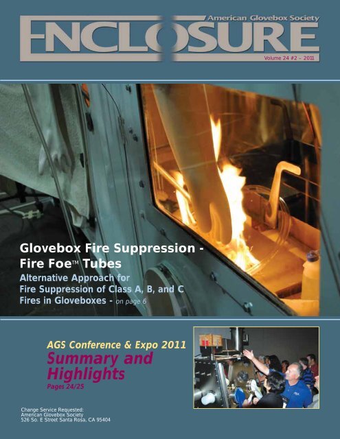
<strong>Glovebox</strong> Fire Suppression -<br />
Fire Foe TM Tubes<br />
Alternative Approach for<br />
Fire Suppression of Class A, B, <strong>and</strong> C<br />
Fires in <strong>Glovebox</strong>es - on page 6<br />
AGS Conference & Expo 2011<br />
<strong>Summary</strong> <strong>and</strong><br />
<strong>Highlights</strong><br />
Pages 24/25<br />
Change Service Requested:<br />
<strong>American</strong> <strong>Glovebox</strong> <strong>Society</strong><br />
526 So. E Street Santa Rosa, CA 95404<br />
Volume 24 #2 – 2011
In This Issue...<br />
<strong>Glovebox</strong> Fire Suppression -<br />
Fire Foe TM Tubes<br />
Alternative Approach for Fire<br />
Suppression of Class A, B, <strong>and</strong> C<br />
Fires in <strong>Glovebox</strong>es<br />
By: Mark S. Rosenberger <strong>and</strong><br />
James A. Tsiagkouris, LANL . . . . . . . . . . . .6<br />
Departments<br />
AGS Sustaining Members . . . . . . . . .15<br />
AGS Conference 2011<br />
<strong>Summary</strong> <strong>and</strong> <strong>Highlights</strong> . . . . . . .24/25<br />
Advertisers<br />
ATI Nuclear Energy . . . . . . . . . . . . . . .18<br />
Controlled Environments Magazine . .13<br />
Diversified Metal Products, Inc. . . . . . .2<br />
Germfree . . . . . . . . . . . . . . . . . . . . . . .5<br />
Guardian Manufacturing Company . .15<br />
Intetgrated Containment Systems . . .10<br />
IP Systems, Inc. . . . . . . . . . . . . . . . . .3<br />
Jennesco Industries, Inc. . . . . . . . . . .15<br />
Jung Gummitechnik . . . . . . . . . . . . . .23<br />
LDS Vacuum Products, Inc . . . . . . . .13<br />
MBraun, Inc. . . . . . . . . . . . . . . . . . . . .11<br />
Merrick & Company . . . . . . . . . . . . . . .9<br />
Piercan USA, Inc. . . . . . . . . . . . . . . . . .4<br />
Premier Technology, Inc. . . . . . . . . . . .7<br />
Renco Corporation . . . . . . . . . . . . . . .21<br />
Servomex Delta-F . . . . . . . . . . . . . . .18<br />
Vacuum Atmospheres Company . . . .28<br />
3
4<br />
The Enclosure<br />
Volume 24, Number 2<br />
Editors<br />
Rodney B. Smith – bsr@y12.doe.gov<br />
Scott Hinds<br />
scott.hinds@merrick.com<br />
Advertising Manager<br />
Crissy Willson<br />
Design <strong>and</strong> Production<br />
Tony Monaco<br />
Publisher<br />
<strong>American</strong> <strong>Glovebox</strong> <strong>Society</strong><br />
The Enclosure is published for the benefit<br />
of the glovebox engineering profession<br />
serving nuclear, biomed, pharmaceutical,<br />
semi-conductor, aerospace technology, <strong>and</strong><br />
other industries.<br />
Circulation: Our continually increasing<br />
circulation is now at 3,100 copies. We have<br />
subscribers throughout the United States,<br />
Canada <strong>and</strong> around the world.<br />
Readership: <strong>Glovebox</strong> designers, users,<br />
engineers, fabricators, manufacturers,<br />
suppliers, contractors, libraries <strong>and</strong> universities.<br />
Advertising: Deadlines for display ads is<br />
the first of each month prior to publication<br />
month for insertion in the January, May <strong>and</strong><br />
August issues.<br />
All rights reserved: Material may be<br />
reproduced or republished with credit to<br />
source <strong>and</strong> author (when indicated).<br />
Submittals: All letters, articles <strong>and</strong><br />
photographs are welcome <strong>and</strong> should be<br />
directed to the editor's attention. Material<br />
will not be returned unless accompanied by<br />
a self-addressed, stamped envelope.<br />
Disclaimer: The information contained<br />
herein is correct to the best of our<br />
knowledge. Recommendations <strong>and</strong> suggestions<br />
are made without guarantee or<br />
representation as to the result since<br />
conditions of use are beyond our control.<br />
The contents are intended as a source of<br />
information.<br />
The Enclosure is published by:<br />
<strong>American</strong> <strong>Glovebox</strong> <strong>Society</strong><br />
526 So. E Street<br />
Santa Rosa, CA 95404<br />
Tel.: (800) 530-1022 or<br />
(707) 527-0444<br />
Fax: (707) 578-4406<br />
E-mail: ags@gloveboxsociety.org<br />
Website: www.gloveboxsociety.org<br />
Postmaster: Send address changes to:<br />
<strong>American</strong> <strong>Glovebox</strong> <strong>Society</strong><br />
526 So. E Street<br />
Santa Rosa, CA 95404<br />
2011/12 Board of Directors<br />
Officers<br />
President<br />
Patrick Westover<br />
Savannah River National Lab<br />
Bus: (803) 725-1941<br />
Patrick.westover@srs.gov<br />
President-Elect<br />
Nathan Levene<br />
Merrick & Company<br />
Bus: (303) 353-3880<br />
nate.levene@merrick.com<br />
Secretary<br />
Paul Contreras<br />
Los Alamos National Security<br />
Bus: (505) 665-3617<br />
pcontreras@lanl.gov<br />
Treasurer<br />
Scott Hinds<br />
Merrick & Company<br />
Bus: (505) 663-4162<br />
scott.hinds@!merrick.com<br />
Immediate Past President<br />
James Spolyar<br />
Aseptic Barrier Systems LLC<br />
Bus: (702) 363-0086<br />
jim.spolyar@us.skan.ch<br />
Moving ?<br />
Board Members<br />
Steve Chunglo<br />
Canberra<br />
Bus: (928) 778-1255<br />
schunglo@7@gmail.com<br />
Justin Dexter<br />
Spectra Tech, Inc.<br />
Bus: (865) 483-7210<br />
jdexter@spectratechinc.com<br />
Carl Fink<br />
CTL Corp.<br />
Bus: (860) 651-9173<br />
crlfnk@aol.com<br />
Lyle Freeman<br />
Premier Technology, Inc.<br />
Bus: (208) 785-2274<br />
lfreeman@ptius.net<br />
Russ Krainiak<br />
Integrated Containment System<br />
Bus: (252) 946-0166<br />
russ@integratedcontainmentsystems.com<br />
Keith Rensberger<br />
IP Systems, Inc.<br />
Bus: (303) 438-157<br />
keithr@ipsysinc.com<br />
Ken Rosenberg<br />
Idaho National Laboratory<br />
Bus: (208) 533-751<br />
kenneth.rosenberg@inl.gov<br />
Ron Smith<br />
Bus: (803) 613-969<br />
rbsmith78@bellsouth.net<br />
Fidel Vigil<br />
Los Alamos National Security<br />
Bus: (505) 665-713<br />
fvigil@lanl.gov<br />
Trish Wright<br />
Los Alamos National Security<br />
Bus: (505) 665-249<br />
pwright@lanl.gov<br />
INTERNATIONAL LIAISONS<br />
Ike Dimayuga, Canadian Liaison<br />
Atomic Energy of Canada, Ltd.<br />
Bus: (613) 584-8811<br />
dimayugaf@aecl.ca<br />
Martyn Page, UK Liaison<br />
AWE, plc<br />
Bus: 44 1189850633<br />
Martyn.page@awe.co.uk<br />
Please let the AGS Central Office know of any changes<br />
in address. Send your name, address, city, state <strong>and</strong><br />
zip code information to:<br />
<strong>American</strong> <strong>Glovebox</strong> <strong>Society</strong><br />
526 So. E Street<br />
Santa Rosa, CA 95404<br />
Bus: (800) 530-1022 or (707) 527-0444<br />
Fax: (707) 578-4406
<strong>Glovebox</strong> Fire Suppression -<br />
Fire Foe TM Tubes<br />
Alternative Approach for Fire Suppression<br />
of Class A, B, <strong>and</strong> C Fires in <strong>Glovebox</strong>es<br />
6<br />
By: Mark S. Rosenberger, ES-DE Fire Protection Services<br />
James A. Tsiagkouris, ES-DE Fire Protection Services<br />
ABSTRACT<br />
Department of Energy (DOE) Orders <strong>and</strong> National Fire<br />
Protection Association (NFPA) Codes <strong>and</strong> St<strong>and</strong>ards require fire<br />
suppression in gloveboxes. Several potential solutions have been<br />
<strong>and</strong> are currently being considered at Los Alamos National<br />
Laboratory (LANL). The objective is to provide reliable, minimally<br />
invasive, <strong>and</strong> seismically robust fire suppression capable of<br />
extinguishing Class A, B, <strong>and</strong> C fires; achieve compliance with DOE<br />
<strong>and</strong> NFPA requirements; <strong>and</strong> provide value-added improvements to<br />
fire safety in gloveboxes. This report provides a brief summary of<br />
current approaches <strong>and</strong> also documents the successful fire tests<br />
conducted to prove that one approach, specifically Fire Foe tubes,<br />
is capable of achieving the requirement to provide reliable fire<br />
protection in gloveboxes in a cost-effective manner.<br />
INTRODUCTION<br />
DOE St<strong>and</strong>ard 1066 <strong>and</strong> NFPA 801 require automatic fire<br />
Mark R. <strong>and</strong> James T. of LANL<br />
suppression to be installed in gloveboxes <strong>and</strong>, potentially, fume<br />
hoods as well. These regulatory requirements stem from actual fire<br />
incidents. The need for some form of automatic fire suppression is<br />
very real due to the nature of glovebox operations <strong>and</strong> the materials contained within gloveboxes <strong>and</strong><br />
fume hoods. For the purpose of this report, we refer to gloveboxes <strong>and</strong> fume hoods as one category,<br />
called enclosures.<br />
Significant resources are spent annually within the DOE Complex to analyze, evaluate, <strong>and</strong><br />
develop engineered <strong>and</strong> administrative controls, develop surveillances, <strong>and</strong> audit the execution of<br />
Authorization Basis programs. These resources are expended in an effort to minimize the potential<br />
effects of an enclosure fire to workers <strong>and</strong> the public, facility <strong>and</strong> programmatic assets, <strong>and</strong> program<br />
mission delivery. Many of these controls rely on worker intervention to either extinguish the fire or to<br />
retard its growth, potentially exposing the worker to hazardous conditions. Additionally, this h<strong>and</strong>s on<br />
approach does not address conditions in which a worker is not present. While a worker may be able<br />
to contain an enclosure fire <strong>and</strong> not be exposed to any detrimental effects, the resulting political<br />
fallout from such an event could significantly delay or prevent a program or even a facility from<br />
restarting operations.<br />
The preceding discussion simply reinforces the need for some form of cost-effective automatic<br />
fire suppression to be installed in enclosures. The features of several existing <strong>and</strong> proposed fire<br />
suppression systems are described below.<br />
Water-based suppression systems are capable of providing fire suppression <strong>and</strong> are inherently<br />
reliable. However, they require penetrations into the glovebox <strong>and</strong> present a potential dilemma in the<br />
event of sprinkler/nozzle activation with respect to volume of water discharged into the enclosure <strong>and</strong><br />
the disposal mechanism for potentially contaminated water. Toppling of a glovebox during a seismic<br />
continued on page 8
continued from page 6<br />
event would eliminate fire suppression in the enclosure with this<br />
type of system. Additionally, the volume of water flow from a<br />
broken pipe would far exceed the volume of water flow from<br />
multiple sprinklers, which would compromise the ability of the<br />
overhead sprinkler system to suppress a fire. A dedicated water<br />
mist system would be incapacitated, but not affect the overhead<br />
suppression system.<br />
Inertion is another approach to minimize the potential for<br />
fire by providing an oxygen deficient atmosphere that does not<br />
support combustion in the enclosure. As such, inertion is not a<br />
“fire suppression” system. The inertion systems are installed to<br />
support process requirements typically involving pyrophoric<br />
metals. Inertion is the predominant approach throughout the<br />
DOE Complex to minimize the possibility of fire in enclosures.<br />
Fire mitigation is reliable up to the point at which the inert<br />
atmosphere can be maintained. Toppling of a glovebox during a<br />
seismic event or loss of electrical power to the vacuum<br />
equipment would compromise the inertion <strong>and</strong> the atmosphere<br />
intended to mitigate the possibility of a fire.<br />
Dry chemical systems, similar to kitchen hood systems, have<br />
been proposed <strong>and</strong> mocked up, but not subject to actual fire<br />
tests to prove their viability. However, dry chemical systems<br />
would require penetrations into the enclosure <strong>and</strong> seismic<br />
modifications to the glovebox to support the agent cylinder,<br />
adding considerable expense to this unproven system. Toppling<br />
of a glovebox during a seismic event would potentially damage<br />
piping or the agent cylinder, compromising its ability to suppress<br />
fire. Additionally, the heat detector which is located in the ceiling,<br />
which acts as a means of activation for the dry chemical system,<br />
would now be located on the side of the glovebox, adversely<br />
affecting the response time for this suppression system if it were<br />
still functional after a seismic event.<br />
Fire Foe is a self-contained fire extinguisher that would be<br />
mounted to the interior ceiling of the enclosure via four to six<br />
bolts. Fire Foe provides a reliable means of fire suppression.<br />
(See appendices for fire test data.) The tubes are seismically<br />
robust, <strong>and</strong> toppling of a glovebox during a seismic event would<br />
not affect the Fire Foe tube. Therefore, the tube would remain<br />
functional <strong>and</strong> provide an active means of fire suppression in<br />
the enclosure as opposed to the aforementioned systems.<br />
8<br />
<strong>Glovebox</strong> Fire Suppression - Fire Foe TM Tubes<br />
<strong>Glovebox</strong> Mockup<br />
FIRE FOE TUBES<br />
Fire Foe tubes are a self-contained, heat intelligent, fire<br />
extinguisher that is UL Listed for Class B (i.e., liquid pool fires)<br />
<strong>and</strong> Class C (i.e., energized electrical circuits) fires in enclosures<br />
of 15, 30, 60, 100, <strong>and</strong> 130 ft3 . The manufacturer also produces<br />
a larger tube for 250-ft3 enclosures. The 250-ft3 tube was not<br />
subject to UL testing <strong>and</strong> does not carry the UL mark. The 250ft3<br />
tube is manufactured to the same st<strong>and</strong>ards <strong>and</strong> with the<br />
same equipment used to produce the smaller UL-Listed tubes.<br />
Fire Test Set Up<br />
Fire Foe tubes do not carry a Class A (i.e., ordinary<br />
combustibles) listing because there is no nationally recognized<br />
test for Class A fires in enclosures less than 3,531- ft3 .<br />
The Fire Foe tubes contain Envirogel®, which is a mixture<br />
of sodium bicarbonate powder (micro-ground) <strong>and</strong> two clean<br />
agent suppressants:, FE-25 <strong>and</strong> FE-36. The sodium<br />
bicarbonate disperses with the clean agent suppressants <strong>and</strong><br />
coats the contents of the enclosure to prevent re-ignition of<br />
combustibles.<br />
Research into the clean agent suppressants revealed they<br />
are both listed for Class A, as well as Class B <strong>and</strong> C fires.<br />
According to the technical bulletins for each clean agent<br />
suppressant:<br />
• FE-25 “The accepted Minimum Extinguishing<br />
Concentration (MEC) for FE-25 for Class-A fires is 6.7%<br />
based on the Class-A fire test requirements found in<br />
Underwriters Laboratories’ (UL) St<strong>and</strong>ard 2166. For<br />
Class-B fires, the MEC is 7% based on cup-burner tests<br />
with n-heptane fuel.… FE-25 is an ideal replacement for<br />
Halon 1301 for the total flooding of enclosures. It can be<br />
used in applications where people are normally present<br />
(normally occupied spaces) for Class-A fire assets.”<br />
• FE-36 “DuPont FE-36 is the most widely used zero<br />
ozone depleting replacement for Halon 1211 in portable<br />
fire extinguishers <strong>and</strong> is approved for use in Class-A, -B,<br />
<strong>and</strong> –C fires.”<br />
The technical bulletins for FE-25 <strong>and</strong> FE-36 indicate<br />
extinguishing characteristics of the clean agent suppressants,<br />
which leads us to believe the tubes could be utilized to<br />
extinguish Class A fires. In addition, the manufacturer of the<br />
tube was confident Fire Foe tubes would prove successful for<br />
extinguishing Class A fires.<br />
continued on page 10
continued from page 8<br />
The Fire Foe tube is constructed of Nylon 6,6 (PA66) that<br />
is 0.065” (1.65-mm) thick with a milled strip that is 0.055” (1.4mm)<br />
thick for st<strong>and</strong>ard temperature tubes <strong>and</strong> 0.085-in. (2.16mm)<br />
thick with a milled strip that is 0.075” (1.9-mm) thick. The<br />
thinner milled strip is intended to be the release/rupture point<br />
at tube activation. The milled portion is identified by a strip of<br />
black tape to facilitate alignment of the tube for optimal<br />
discharge during installation. Tubes are sealed at the ends with<br />
12L14 carbon steel caps. One end of the tube is fitted with a fire<br />
extinguisher-type gauge, which provides an easy means to<br />
inspect the tube to ensure it is properly pressurized. The operating<br />
range of the gauge is 75 psi to 121 psi (i.e., the green b<strong>and</strong><br />
of the gauge). The other end of the tube is fitted with a threaded<br />
fitting <strong>and</strong> spring-loaded plunger assembly that is utilized to<br />
fill, pressurize, <strong>and</strong> seal the tube. Tubes can be manufactured<br />
with 304 stainless steel end caps instead of 12L14 carbon steel<br />
to suit glovebox working environments.<br />
Fire Foe uses patented technology <strong>and</strong> specially formulated<br />
heat-intelligent nylon tubes, eliminating the need for<br />
additional heat detectors. There is no need for an initiating<br />
device to activate the tube or any type of power supply, making<br />
Fire Foe a cost-effective, automatic fire extinguishing system.<br />
The narrow tube profile <strong>and</strong> bolt-on simplicity save time <strong>and</strong><br />
money when fitting or retro-fitting this fire suppression system,<br />
minimizing downtime <strong>and</strong> loss of productivity.<br />
St<strong>and</strong>ard tubes are effective in ambient operating temperatures<br />
up to 175°F (80°C) <strong>and</strong> are accredited by UL up to 130°F<br />
10<br />
<strong>Glovebox</strong> Fire Suppression - Fire Foe TM Tubes<br />
(55°C). High-temperature tubes are suitable for use in ambient<br />
operating temperatures up to 220°F (105°C). The manufacturer<br />
can provide dummy tubes with heat recording labels to help<br />
determine maximum ambient operating temperature in the<br />
enclosure to determine which temperature tube should be<br />
installed if there is any uncertainty.<br />
Fire Foe reacts to all fires, slow burning over time as well<br />
as flash fires. Tubes are normally pressurized to 100 psi at room<br />
temperature. Below 175°F (80°C), the Fire Foe tube is stable.<br />
When the heat from a fire climbs above 175°F (80°C), the Fire<br />
Foe triggers the heat-intelligent nylon tube, which begins to<br />
activate (i.e., soften). High-temperature tubes will begin to selfactivate<br />
above 240°F (115°C). As the temperature rises, the<br />
internal pressure of Envirogel ® increases, eventually rupturing<br />
the tube along a milled release strip, releasing the Envirogel ® . At<br />
316°F (150°C), st<strong>and</strong>ard temperature tubes discharge instantly.<br />
The Envirogel® undergoes a phase change from gel to gas,<br />
which instantly interrupts the combustion process, absorbing<br />
heat <strong>and</strong> chemically extinguishing the fire. The non-toxic <strong>and</strong><br />
non-corrosive sodium bicarbonate powder travels with the gas,<br />
coating any combustible material to prevent re-ignition.<br />
Tubes are vibration- <strong>and</strong> corrosion-resistant, unaffected by<br />
low temperatures, <strong>and</strong> will not activate before the predetermined<br />
temperature has been reached (500 successful<br />
individual activations were performed sequentially, in<br />
accordance with UL 2166, to secure UL approval).<br />
continued on page 12
continued from page 10<br />
Fire Foe is provided with an integral pressure gauge for<br />
easy monitoring. Additionally, the tubes are available with an<br />
integral pressure switch that can be tied into the fire alarm<br />
system for monitoring.<br />
Periodic maintenance for the tubes can be accomplished<br />
by a visual inspection of the gauge located on the end of the<br />
tube. A log should be maintained to confirm that the pressure is<br />
still within the acceptable range (i.e., green b<strong>and</strong> on gauge).<br />
DEVELOPMENT OF TEST PROTOCOL<br />
LANL’s ES-DE Fire Protection Division developed a phased<br />
test plan to minimize financial exposure to LANL in the event<br />
proof-of-concept tests were not successful. The initial phase<br />
was comprised of proof-of-concept testing at the manufacturer’s<br />
facility. Successful proof-of-concept testing would be<br />
followed up with subsequent phases that consisted of Nationally<br />
Recognized Testing Laboratory (NRTL) fire testing based on the<br />
developed test protocol.<br />
As previously stated, there is not a nationally recognized<br />
test for Class A fires in enclosures. We used this to our<br />
advantage to develop a test protocol tailored to needs here at<br />
LANL. Specifically, the Class A combustibles would consist of a<br />
wood crib, boxes of Kim-wipes, <strong>and</strong> Tygon tubing. Class B<br />
combustibles would be comprised of acetone <strong>and</strong> cutting oil.<br />
Class C combustibles would consist of wire bundles comprised<br />
of #16 AWG, #18 AWG, <strong>and</strong> coaxial cables. The test protocol<br />
was prepared in conjunction with QuickFire, the manufacturer of<br />
Fire Foe tubes. Due to the lack of a Class A listing for any<br />
tubes, we developed the test protocol based on the largest tube<br />
(i.e., 250-ft 3 ) tube manufactured by QuickFire to yield the<br />
greatest benefit to the Laboratory.<br />
PROOF-OF-CONCEPT TESTING<br />
LANL provided sketches <strong>and</strong> details to QuickFire to permit<br />
them to fabricate a glovebox mock-up at their facility to perform<br />
fire tests. Dimensions of the mock-up were 8’L x 5’W x 6’H,<br />
12<br />
Fire in <strong>Glovebox</strong> with Glove<br />
<strong>Glovebox</strong> Fire Suppression - Fire Foe TM Tubes<br />
yielding a 250-ft 3 enclosure.LANL provided windows, window<br />
gaskets, gloves, <strong>and</strong> HEPA exhaust filters identical to equipment<br />
used on gloveboxes at LANL.<br />
When the glovebox mock-up was completed, the manufacturer<br />
installed thermocouples to record the temperature profile<br />
in the enclosure, pressure transducers to record the pressure<br />
profile in the enclosure, <strong>and</strong> a blower <strong>and</strong> ducting to provide the<br />
airflow indicated in the test protocol. The thermocouples <strong>and</strong><br />
pressure transducers were connected to a computer to record<br />
data for all proof-of-concept fire tests. Airflow was measured<br />
with an anemometer <strong>and</strong> set to 250 cfm (i.e., one air change<br />
per minute). The airflow used for the fire tests is greater than<br />
that used for gloveboxes, <strong>and</strong> more consistent with fume hoods,<br />
thus opening the door to the possibility that the tubes could be<br />
used in fume hoods—<strong>and</strong> providing a dual-use benefit of the<br />
tubes for LANL. The air intake opening was adjusted to provide<br />
negative pressure as indicated in the test protocol. Negative<br />
pressure is required in the enclosure¸ with respect to the room<br />
in which it is located, to ensure the<br />
glovebox does not discharge its<br />
contained environment to the<br />
surrounding room in the event of a<br />
glove breach or other breach of the<br />
enclosure. The requirement to<br />
maintain negative pressure within the<br />
enclosure was a concern because of<br />
the fact that the internal pressure<br />
inside the Fire Foe tube is approximately<br />
600 psi at rupture, which<br />
intuitively would generate a pressure<br />
surge. The concern was unfounded,<br />
as activation of the tube resulted in a<br />
negative pressure spike, actually<br />
pulling the gloves into the enclosure.<br />
<strong>Summary</strong> of Proof-of-<br />
Concept Test Results<br />
QuickFire performed numerous<br />
fire tests at its facility in accordance<br />
with our co-established test protocol.<br />
Fire tests were performed utilizing<br />
Class A combustibles, Class B<br />
combustibles, <strong>and</strong> Class C1 combustibles fires <strong>and</strong> various combinations of combustibles to<br />
confirm the Fire Foe tube is capable of successfully extinguishing<br />
all three classes of fires in enclosures. Class A combustibles<br />
used for this series of fire tests consisted of wood cribs constructed<br />
of nominally 1”D x 2”W x 10”L pine into a 10” cube stuffed<br />
with crumpled newspaper to represent a deep-seated fire.<br />
The individual proof-of-concept fire tests performed by<br />
QuickFire are referred to as “Test Protocol #” in its report, “Fire<br />
Foe in 250 CF <strong>Glovebox</strong> Proof-of-Concept Test Report”. This<br />
report is available upon request.<br />
QuickFire performed 10 proof-of-concept tests at –3/4”<br />
water column (i.e., glovebox negative pressure requirement)<br />
that were 100% successful. The proof-of-concept tests used<br />
various combustibles as defined in the test protocol. Successful<br />
testing led to an additional set of tests that were performed<br />
continued on page 14
continued from page 12<br />
September 20, 2010, at QuickFire’s facility in Fort Wayne, IN,<br />
<strong>and</strong> witnessed by LANL representatives Mark S. Rosenberger<br />
<strong>and</strong> James A. Tsiagkouris of ES-DE Fire Protection Division. The<br />
pressure was adjusted to –1/4” water column for this next<br />
series of fire tests to more closely reflect actual glovebox<br />
conditions found at LANL. An additional four proof-of-concept<br />
tests were performed that were also 100% successful.<br />
The positive pressure surge envisioned at tube activation/rupture<br />
proved to be unfounded, as the pressure surge was<br />
negative due to the phase change <strong>and</strong> cooling effect of<br />
Envirogel ® . The only positive pressure changes were the result<br />
of involvement of combustibles during the fire tests.<br />
The Fire Foe tube was located along the longitudinal<br />
centerline of the glovebox mock-up for all 14 proof-of-concept<br />
tests performed at the manufacturers’ facility. As we worked<br />
through proof-of-concept testing, we realized that even though<br />
the centerline of the glovebox was the optimal location for the<br />
tube, it was not the most accessible location for attachment of<br />
the tube. Additionally, equipment or processes used in the<br />
glovebox may preclude locating the tube in the centerline of the<br />
enclosure. We requested additional fire tests with the tube<br />
located closer to the side of the enclosure, which would have a<br />
two-fold benefit: allowing easy access to the tube from the<br />
glove ports <strong>and</strong> providing redundancy of suppression via installation<br />
of tubes on each side of the<br />
enclosure. QuickFire performed<br />
additional proof-of-concept tests<br />
with the tube located nominally 6”<br />
below the ceiling <strong>and</strong> 6” from the<br />
side wall; the tests were 100%<br />
successful.<br />
All fire test conditions were<br />
maintained for a minimum of 5<br />
minutes after activation of the Fire<br />
Foe tube to confirm there was not<br />
any re-ignition of combustibles or<br />
any remaining embers that would<br />
support continued combustion in<br />
accordance with UL guidelines.<br />
Table 1 shows a summary of the<br />
test results.<br />
Table 1. <strong>Summary</strong> of Proofof-Concept<br />
Test Results<br />
At the end of this entire testing<br />
cycle, the gloves in the gloveboxes<br />
were still intact <strong>and</strong> pliable without<br />
any breaches, but they did have<br />
some discoloration because of their<br />
proximity to the fire. The windows<br />
did not suffer any damage or<br />
clouding, <strong>and</strong> the window gaskets<br />
showed no signs of fire damage.<br />
NRTL TESTING<br />
Successful proof-of-concept testing permitted us to<br />
proceed with NRTL testing, which was to be witnessed by LANL<br />
representatives. Intertek, an NRTL, agreed that testing <strong>and</strong> setup<br />
would be easier if the glovebox mock-up remained at<br />
QuickFire’s facility. Follow-up NRTL testing was performed<br />
14<br />
<strong>Glovebox</strong> Fire Suppression - Fire Foe TM Tubes<br />
October 19, 2010, <strong>and</strong> witnessed by LANL representatives<br />
Mark S. Rosenberger <strong>and</strong> James A. Tsiagkouris. The purpose of<br />
contracting with an NRTL was to provide independent verification<br />
of the test results. Additionally, the NRTL has the ability to<br />
provide long-term inspections at the manufacturer’s facility to<br />
guarantee to LANL that tubes are manufactured to the same<br />
specifications as the tubes used for fire tests.<br />
<strong>Summary</strong> of NRTL Test Results<br />
NRTL monitored <strong>and</strong> recorded the six tests that were<br />
performed. The Fire Foe tube successfully extinguished fire<br />
tests 1, 3, 4, 5, <strong>and</strong> 6. For this series of fire tests, we used a UL<br />
1975 wood crib assembly. The UL 1975 wood crib has a<br />
smaller heat release rate than the wood crib used for the proofof-concept<br />
fire tests. To initiate the fire test, the wood excelsior<br />
inside the base of the wood crib was ignited <strong>and</strong> allowed to<br />
burn for 1 minute prior to introduction of acetone. The pressure<br />
wave generated when the acetone became involved in the fire<br />
had an extinguishing effect on the wood crib fire. This effect is<br />
evident in fire test no. 2 as the fire burned out prior to reaching<br />
a temperature that was sufficient to activate the tube. To<br />
minimize the extinguishing effect experienced during introduction<br />
<strong>and</strong> involvement of acetone, we decided to allow the wood<br />
crib to burn for 2 minutes for fire tests 5 <strong>and</strong> 6. Table 2<br />
summaries the NRTL test results.<br />
Table 1. <strong>Summary</strong> of Proof-of-Concept Test Results<br />
continued on page 16
AGS Sustaining Members<br />
ABW Technologies, Inc.<br />
6720 191st Pl NE<br />
Arlington, WA 98223-4666<br />
Bus: (360) 618-4400<br />
Fax: (360) 618-4444<br />
adura@abwtec.com<br />
Babcock & Wilcox<br />
Clinch River, LLC<br />
400 Centrifuge Way<br />
Oak Ridge, TN 37830<br />
Bus: (865) 481-7156<br />
Fax: (865) 241-7135<br />
cdirwin@babcock.com<br />
Byers Precision Fabricators, Inc.<br />
675 Dana Road<br />
Hendersonville, NC 28792<br />
Bus: (828) 693-4088<br />
Fax: (828) 692-5753<br />
rogerbyers@byersprecision.com<br />
M. Braun Inc.<br />
14 Marin Way<br />
Stratham, NH 03885-2578<br />
Bus: (603) 773-9333<br />
Fax: (603) 773-0008<br />
m.boutin@mbraunusa.com<br />
Robatel Technologies, LLC<br />
PO Box 12007<br />
Roanoke, VA 24022<br />
Bus: (540) 989-2878<br />
tgrochowski@robateltech.com<br />
Oregon Iron Works, Inc.<br />
9400 SE Lawnfield Rd.<br />
Clackamas, OR 97015<br />
Bus: (503) 653-6300<br />
To become a sustaining<br />
member, contact the<br />
AGS Central Office<br />
(800)530-1022 or<br />
ags@gloveboxsociety.org<br />
15
continued from page 14<br />
Table 2. <strong>Summary</strong> of NRTL Test Results<br />
ENVIRONMENTAL IMPACT<br />
Based on fire tests performed to validate this suppression<br />
system, Fire Foe tubes typically discharge within four minutes<br />
in the event of a fire in the enclosure. The resulting discharge<br />
will introduce the Envirogel ® into the enclosure. At the time of<br />
discharge, the Envirogel ® will consist of the components <strong>and</strong><br />
forms listed in Table 3.<br />
Table 3. Envirogel ® Components <strong>and</strong> Forms<br />
Dupont, Inc., manufactures the fire extinguishing agents FE-<br />
25 <strong>and</strong> FE-36 as Halon 1301 replacements. Both agents<br />
have been Significant New Alternatives Policy (SNAP) programapproved<br />
by the Environmental Protection Agency (EPA) <strong>and</strong><br />
are suitable for direct release to the atmosphere as ozone nondepleting<br />
agents.<br />
The products of combustion that will be produced in a fire<br />
event cannot be fully anticipated because they are dependent<br />
on the contents of the enclosure <strong>and</strong> the materials involved in<br />
the fire. However, consistent with any industrial fire event, the<br />
agents will interact with the combustion process <strong>and</strong> will<br />
generate a number of compounds that are adverse to health<br />
safety <strong>and</strong> the environment.<br />
In the event of a small fire, it would be fully anticipated, as<br />
long as the exhaust system remains functional, that the products<br />
of combustion would be contained by the primary exhaust<br />
system. This would provide filtering of the smoke prior to<br />
discharge to the environment. If the fire were to involve gloves<br />
16<br />
<strong>Glovebox</strong> Fire Suppression - Fire Foe TM Tubes<br />
in a glovebox or be at the face<br />
of a hood, then the products<br />
could be discharged into the<br />
adjacent air spaces. This<br />
smoke is fully anticipated to<br />
be processed by the secondary<br />
air h<strong>and</strong>ling systems<br />
supporting the affected facility.<br />
This type of scenario is<br />
normally addressed as part of<br />
the Authorization Basis for a<br />
facility but would have to be<br />
reviewed for any potential<br />
impact to the bounding<br />
design basis accidents that<br />
have been developed.<br />
Decommissioning<br />
Decommissioning of the tubes presents several challenges,<br />
listed below:<br />
• Potential radiological surface contamination on the tube<br />
• Relieving internal pressure of the tube<br />
• Disposal of the tube contents<br />
• Disposal of the tube<br />
We have explored methods to decommission the tubes. We<br />
propose the following steps for disposal of tubes that are not<br />
provided with an integrated pressure switch:<br />
1. Identify the tube for decommissioning.<br />
2. Remove the identified tube from the mounting bracket.<br />
3. Remove the screw end cap from the tube, exposing<br />
the spring-loaded valve.<br />
4. Screw in the pressure relief tool <strong>and</strong> attach a capture<br />
bag to the discharge end of the relief tool.<br />
5. Engage spring-loaded valve by rotating the tube <strong>and</strong><br />
release internal pressure; any contents of the tube will<br />
be captured in the attached bag.<br />
6. Empty the remaining contents of the tube into the bag.<br />
7. Cut tube as required to accommodate removal of tube<br />
from the enclosure.<br />
In the event of potential radiological surface contamination,<br />
the tubes will have to be disposed of as contaminated waste.<br />
Due to the nature of the tube’s surface materials, it is not anticipated<br />
they could be adequately decontaminated to allow for a<br />
free release from the environments in which they are installed.<br />
Therefore, decommissioning will have to be performed inside<br />
the enclosure or transferred to a dedicated enclosure for<br />
decommissioning.<br />
Once the pressure in the tube is relieved, <strong>and</strong> the contents<br />
of the tube (i.e., sodium bicarbonate powder) are removed, the<br />
body of the tube can easily be cut, by a h<strong>and</strong> or power saw, into<br />
shorter lengths as required to support removal from the<br />
continued on next page
continued from previous page<br />
enclosure by st<strong>and</strong>ard means. The cut sections of tube targeted<br />
for waste would simply be processed out of the enclosure as<br />
non-compactable waste.<br />
The nitrogen gas used to charge the tube could be released<br />
in the enclosure itself <strong>and</strong> allowed to discharge with the exhaust<br />
air from the glovebox through the facility’s filtered exhaust<br />
system. Additionally, at atmospheric pressure, the FE-25 <strong>and</strong><br />
FE-36 clean agent suppressants that comprise the Envirogel®<br />
vaporize <strong>and</strong> are carried out with the nitrogen gas. This leaves<br />
only the sodium bicarbonate powder in the tube, which would<br />
be processed with the spent tube <strong>and</strong> disposed of as noncompactable<br />
waste.<br />
Accidental Discharge<br />
There is always the possibility of an accidental discharge of<br />
the tube. One scenario would be premature failure of the tube.<br />
The most likely cause of this would be a st<strong>and</strong>ard temperature<br />
tube placed in an environment in which it sees higher than<br />
anticipated ambient temperatures, similar to the failure<br />
mechanism of a fire sprinkler in this type of environment. For a<br />
fire sprinkler, this type of failure would result in the fire suppression<br />
system activating <strong>and</strong> discharging water from the activated<br />
sprinkler into the protected area. In the event of a tube<br />
discharge, the result would be similar; the tube would rupture<br />
<strong>and</strong> the agent would be released into the protected enclosure.<br />
Another scenario would be mechanical impact resulting in<br />
a puncture or breach of the tube. Once again, this scenario<br />
would be similar to a fire sprinkler placed in a physical location<br />
where the sprinkler could be damaged by physical impact. In<br />
the case of a sprinkler, physical damage could result in damage<br />
that causes it to leak or could result in the thermal element<br />
being dislodged, causing a full flow from the sprinkler. In either<br />
case, the result is the same: the fire suppression system would<br />
be impaired <strong>and</strong> water would be flowing in the facility. The tubes<br />
are more robust than a sprinkler but could be punctured, which<br />
would result in the agent being discharged from the tube into<br />
the protected enclosure. In this scenario, the tube would have<br />
to be replaced.<br />
Following the battery of fire tests performed to prove Fire<br />
Foe extinguishes Class A, B, <strong>and</strong> C fires in enclosures, a<br />
puncture test was performed <strong>and</strong> recorded to help underst<strong>and</strong><br />
what would happen if a tube was accidentally physically<br />
damaged. The test results showed that the agent would<br />
discharge in powder form. If a glovebox technician was present<br />
at the time of damage, there would be positive visual indication<br />
of the agent discharging from the tube. Conversely, if a glovebox<br />
technician was not present at the time of the accidental<br />
discharge, there would be visible indications in the form of<br />
sodium bicarbonate powder coating the interior of the<br />
enclosure <strong>and</strong> its contents.<br />
SEISMIC CONSIDERATIONS<br />
Seismic considerations for systems, structures, or<br />
components (SSCs) installed in several LANL facilities are of<br />
extreme importance. Seismic events present real <strong>and</strong> challenging<br />
problems in designing engineering controls, which must<br />
ensure that these facilities are safe after a design basis event.<br />
One of the most challenging accident scenarios considered as<br />
part of the Authorization Basis analysis is the post-seismic fire<br />
event. In accordance with DOE St<strong>and</strong>ard 1066 requirements,<br />
automatic fire suppression is required to be installed in all<br />
gloveboxes. The following is a listing of the best c<strong>and</strong>idates to<br />
fulfill this requirement:<br />
1. Water-based suppression (i.e., fire sprinklers, <strong>and</strong><br />
water mist)<br />
2. Dry chemical<br />
3. Inertion<br />
4. Fire Foe Tubes<br />
Each of the above systems could be installed in an<br />
enclosure, but each one presents its own set of challenges in a<br />
post-seismic fire scenario.<br />
Water-Based Suppression<br />
Fire Sprinkler<br />
Fire sprinklers are arguably the most cost-effective means<br />
of automatic fire suppression available. Fire sprinklers have a<br />
history of effective fire suppression in many environments. Fire<br />
sprinklers can either be piped to the overhead fire suppression<br />
system or piped independently to each enclosure. These<br />
systems draw from water sources located outside of the facility<br />
they are protecting. However, the presence of water within the<br />
enclosures at LANL can present major problems for many<br />
processes, primarily the criticality of the materials present in the<br />
enclosures.<br />
Given a seismic event, the water distribution system may<br />
not be intact <strong>and</strong>, therefore, no water would be available to the<br />
fire sprinkler system. Even if the outside water supply were to<br />
survive the seismic event, several issues remain with the seismic<br />
response of the facility <strong>and</strong> its contents. Facility interior walls<br />
could shear the suppression system piping, <strong>and</strong> equipment<br />
within the facility could shift <strong>and</strong> damage the piping, resulting in<br />
loss of water to the system. Another concern as a result of a<br />
seismic event is that of the enclosure itself. The enclosure could<br />
tip over if the support st<strong>and</strong> failed. This would result in the<br />
sprinkler piping breaking <strong>and</strong> water being discharged from the<br />
system, but not into the enclosure, which would also compromise<br />
the ability of the overhead system to suppress a fire.<br />
Water Mist<br />
Water mist fire suppression systems use a limited-volume<br />
water supply <strong>and</strong> deliver the water at a high velocity through a<br />
nozzle designed to atomize the water stream into a fog. These<br />
systems are designed to use much smaller amounts of water<br />
than fire sprinkler systems—an advantage when considering<br />
criticality concerns. In another advantage, water mist systems<br />
are typically designed with limited independent water supplies.<br />
These systems are fully listed <strong>and</strong> recognized for distribution<br />
over time, which would allow for their application in environments<br />
that require active exhaust systems. System downtime<br />
would be minimal if the water mist system discharged as long as<br />
spare discharge nozzles, water, <strong>and</strong> gas cylinders were<br />
available.<br />
However, water mist systems are still vulnerable to seismic<br />
response of the facility <strong>and</strong> its contents just as the st<strong>and</strong>ard fire<br />
suppression system is.<br />
An additional concern is the life cycle cost of the system.<br />
Because water mist systems are limited supply systems, several<br />
continued on next page<br />
17
continued from previous page<br />
of them would have to be installed to support a single facility.<br />
Additionally, water mist systems are more complex than<br />
traditional fire suppression systems <strong>and</strong>, therefore, require more<br />
rigorous periodic maintenance. The periodic ITM will increase<br />
the overall operational costs of the facility significantly.<br />
Dry Chemical<br />
Dry chemical systems use dry powder fire suppression<br />
agents to suppress a fire. These systems have dedicated limited<br />
supplies similar to the water mist system. These systems avoid<br />
the criticality concerns that the water-based systems present.<br />
However, they are also susceptible to the seismic response<br />
of the facility <strong>and</strong> its contents. These systems, due to their<br />
complexity, have the same reliability concerns as water mist<br />
systems. They also have the same life cycle costs that the water<br />
mist systems have because of the ITM requirements.<br />
Dry chemical systems are not allowed for “discharge-overtime”<br />
applications when installed as listed by UL or Factory<br />
Mutual (FM). Additionally, NFPA 17, “St<strong>and</strong>ard for Dry Chemical<br />
Extinguishing Systems,” does not permit them to be installed as<br />
discharge-over-time applications. Current systems being<br />
incorporated at LANL have installed flow restriction devices that<br />
prolong the duration of the agent discharge. Installation of these<br />
flow restriction devices places the overall system outside of its<br />
approved NRTL listing requirements. While they may use an<br />
ABC-listed extinguishing agent, dry chemical systems are only<br />
listed for BC enclosure fire applications since there is no nation-<br />
18<br />
<strong>Glovebox</strong> Fire Suppression - Fire Foe TM Tubes<br />
ally recognized st<strong>and</strong>ard test for Class A enclosure fires. To<br />
satisfy these issues, an extensive testing plan will need to be<br />
developed <strong>and</strong> executed before installing a dry chemical system<br />
in an enclosure is possible.<br />
Inertion<br />
Inertion, while not technically a fire suppression system,<br />
needs to be discussed at part of this report because it is currently<br />
the predominant method used to mitigate fires in enclosures.<br />
Typical inertion systems are installed in enclosures that perform<br />
processes or h<strong>and</strong>le materials that may react in an environment<br />
containing oxygen. These systems typically dehumidify the<br />
atmosphere <strong>and</strong> displace oxygen with nitrogen or argon,<br />
lowering the oxygen content. The resultant oxygen concentration<br />
is less than 1% compared with the 21% present in the air<br />
we breathe. This controlled low level of oxygen does not support<br />
the combustion process. Inertion systems are typically package<br />
units that are sized, selected, <strong>and</strong> installed as part of the overall<br />
enclosure.<br />
The systems are relatively complex with vacuum pumps,<br />
inert gas regulation, system controls, oxygen <strong>and</strong> humidity<br />
monitors, etc. The systems have good reliability as long as<br />
electrical power is maintained. Inertion within the enclosure<br />
would be lost in the event the system is de-energized or loses<br />
power. Additionally, inertion systems are vulnerable to the same<br />
seismic response issues of the facility <strong>and</strong> its contents as waterbased<br />
fire suppression <strong>and</strong> dry chemical systems. However,<br />
inertion is more dependent on enclosure integrity than waterbased<br />
fire suppression <strong>and</strong> dry chemical systems. Therefore, in<br />
a post-seismic fire event, inertion capabilities would be compromised<br />
by the loss of a window, glove, or gasket.<br />
As previously stated, inertion systems are not fire suppression<br />
systems, but rather a means to create an atmosphere that<br />
does not support combustion. This complicates the fire alarm<br />
interface for monitoring <strong>and</strong> fire department response to alarms<br />
generated by the system. Engineering evaluations will have to be<br />
performed to determine which portions of these systems would<br />
have to be monitored <strong>and</strong> what the proper fire alarm response<br />
would be. This presents potential Authorization Basis impacts<br />
that would have to be evaluated.<br />
Fire Foe Tube<br />
As described in previous sections of this report, the Fire<br />
Foe tube is a self-contained, self-actuating extinguisher. The<br />
tube contains a proprietary mixture of FE-25, FE-36 <strong>and</strong><br />
micro ground sodium bicarbonate called Envirogel ® as its<br />
extinguishing agent. The tubes, similar to the dry chemical<br />
system, do not use water, thus avoiding potential criticality<br />
concerns within the enclosures. The tubes are mounted entirely<br />
within the enclosure, eliminating the need for open or waterfilled<br />
piping to be installed through the enclosure <strong>and</strong>, therefore,<br />
not exp<strong>and</strong>ing the enclosure envelope. This reduces potential<br />
issues that may increase the leak path factor associated with an<br />
enclosure. Leak path factors result from additional penetrations<br />
through the glovebox <strong>and</strong> subsequently affect the design basis<br />
calculations.<br />
Issues associated with seismic events are greatly reduced<br />
because the tubes are a passive engineering control. They do<br />
not require any support SSC to be functioning in a post-seismic<br />
continued on page 20
continued from page 18<br />
event for them to be able to function. Post-seismic event issues<br />
are further reduced if the installation is done in accordance with<br />
the proposed general design criteria, which would require<br />
redundant tubes be installed within an enclosure. If an<br />
enclosure were to fall over at any angle up to 90° degrees from<br />
the vertical, a tube would still be in the upper portion of the<br />
enclosure <strong>and</strong> exposed to heat generated by any fire within the<br />
enclosure. If the fire is of sufficient energy, the tube will activate<br />
to extinguish the fire.<br />
Unlike the dry chemical system, the Fire Foe tubes are<br />
specifically listed <strong>and</strong> have been tested for environments that<br />
have up to one air change per minute. This provides a Listed <strong>and</strong><br />
tested solution for discharge-over-time applications that are<br />
required for environments exhausting the enclosure to the<br />
atmosphere. This airflow rate exceeds typical exhaust flow rates<br />
for gloveboxes <strong>and</strong> is more in line with flow rate requirements for<br />
fume hoods.<br />
The tubes are currently UL Listed for Class B <strong>and</strong> C fires in<br />
enclosures up to 130 ft3 . As discussed in earlier sections of this<br />
report, the individual agents comprising the Envirogel ® mixture<br />
are listed as Class A, B, <strong>and</strong> C extinguishing agents. This report<br />
documents the successful completion of fire testing that<br />
demonstrates, <strong>and</strong> has been verified by an independent NRTL,<br />
that the tubes are capable of extinguishing Class A, B, <strong>and</strong> C<br />
fires in enclosure up to 250 ft3 under negative pressure with<br />
airflow equivalent to one air change per minute.<br />
However, the Fire Foe tubes may not be suitable for installation<br />
in every glovebox at LANL because of the varying<br />
environments within the enclosures. High alpha radiation<br />
environments are a concern because these particles deposit all<br />
of their energy at the surface of the material they contact.<br />
Additionally, there may be aqueous chemical environments that<br />
attack the nylon tube in a manner that will result in an abbreviated<br />
unacceptable service life. Radiation exposure tests<br />
addressing the alpha contamination issues should be<br />
performed, <strong>and</strong> an evaluation of the aqueous chemical environment<br />
for each c<strong>and</strong>idate enclosure will have to be evaluated<br />
prior to installation. These more aggressive environments will<br />
have to be reviewed to ensure they are compatible with the Fire<br />
Foe tube.<br />
RADIOLOGICAL AGE TESTING<br />
Currently, the manufacturer does not list a recommended<br />
service life for the tube. The manufacturer does offer a five-year<br />
warranty on the tube. This warranty covers manufacturing <strong>and</strong><br />
material defects for that period of time. In discussions of a service<br />
life for tubes installed at LANL, the driving concern is how the<br />
Nylon 6,6 will react over time in a radiological environment.<br />
Alpha radiation presents the greatest challenge to the<br />
service life <strong>and</strong> integrity of the tube because alpha particles<br />
deposit their energy at the surface of the material. The average<br />
depth of penetration at the surface is 25 to 30 microns. This<br />
depth is nominally 2% of the wall thickness of the tube.<br />
Initial literature reviews of Nylon 6,6 indicate that it will<br />
respond better in a radiological environment than Teflon. The<br />
issue with the published literature for Nylon 6,6 is that the literature<br />
does not present damage due specifically to alpha<br />
radiation; the nomographs typically present radiological<br />
damage information based on a combined radiation field. The<br />
most relevant information available are the results of the Teflon<br />
20<br />
<strong>Glovebox</strong> Fire Suppression - Fire Foe TM Tubes<br />
testing performed by LANL. 2 Results of this testing showed that<br />
at 109 rad, the Teflon samples showed cracking, <strong>and</strong> at 1011 rad,<br />
the Teflon evaporated. Due to the lack of specific data for Nylon<br />
6,6, some type of testing <strong>and</strong>/or material monitoring should be<br />
established until a service life can be formally established for<br />
the tubes in radiological environments.<br />
Accelerated age testing could be conducted by applying<br />
(i.e., painting) Uranium 238 (U238) to coupons of the Nylon 6,6,<br />
allowing the samples to age for specified periods, then cleaning<br />
the sample by removing the U238 from the coupon <strong>and</strong> analyzing<br />
the surface characteristics by comparing them to control<br />
sample of Nylon 6,6. A second approach would be to take<br />
coupons of the material <strong>and</strong> place them in various enclosures<br />
with varying environments <strong>and</strong> analyze the surface characteristics<br />
at specified intervals. A combination of these two approaches<br />
could be used to provide information to establish <strong>and</strong> formalize<br />
a service life for the tubes.<br />
The accelerated age testing by applying U238 would<br />
present the most conservative results due to the high activity<br />
levels <strong>and</strong> heat generated by U238 particles relative to other<br />
materials. In the case of coupon monitoring, a methodology of<br />
monitoring the enclosure environment over the course of the<br />
testing period would have to be developed <strong>and</strong> executed to<br />
provide meaningful data for determining radiological service life<br />
effects. A formal experimental plan will need to be developed<br />
<strong>and</strong> executed to obtain definitive information.<br />
DESIGN CRITERIA<br />
The following design criteria are considered the minimum<br />
guidance for manufacture <strong>and</strong> installation of the tubes within<br />
enclosures at LANL:<br />
Tube:<br />
1. Tube body shall be constructed of Nylon 6,6.<br />
2. Two activation temperatures shall be provided:<br />
a. St<strong>and</strong>ard Temperature: 175 oF for installation in<br />
enclosures without heat-generating equipment.<br />
b. High Temperature: 220oF for installation in<br />
enclosures with heat-generating equipment.<br />
3. Tube end caps shall be constructed of 304 stainless<br />
steel (SS).<br />
4. Pressure gauge assembly shall be 304 SS.<br />
5. Nominal wall thickness of the tube body shall be<br />
a. St<strong>and</strong>ard temperature: 0.065” +/- 0.005”<br />
b. High temperature: 0.085” +/- 0.005”<br />
6. Wall thickness of machined activation strip:<br />
a. St<strong>and</strong>ard temperature: 0.055” +/- 0.005”<br />
b. High temperature: 0.075” +/- 0.005”<br />
7. Machined activation strip shall start along the tube<br />
body 1.75” +/- 0.25” from the end cap.<br />
8. Machined activation strip shall be 0.875” +/- 0/125”<br />
wide, along the longitudinal axis of the tube.<br />
continued on page 22
continued from page 20<br />
9. Tube shall be capable of being discharged within the<br />
enclosure.<br />
10. Tube shall be capable of being fitted with a pressure<br />
switch capable of being monitored by a fire alarm<br />
system.<br />
11. The pressure switch shall be a normally open dry<br />
contact type capable of being placed within the same<br />
environment as the tube.<br />
12. Mounting bracket assembly shall be manufactured<br />
from 304 SS.<br />
Location<br />
1. The tube shall be rigidly mounted within the enclosure.<br />
2. The tube centerline shall be placed at 4” +/-2” from the<br />
ceiling of the enclosure <strong>and</strong> a minimum of 6”+/- 0.5”<br />
from the wall of the enclosure.<br />
3. The activation strip should be orientated in such a<br />
direction that it ensures coverage throughout the<br />
enclosure. Nominally, the discharge strip shall be<br />
orientated away from the nearest wall <strong>and</strong> at a 45°<br />
angle downward (i.e., 225° or 315°).<br />
Size <strong>and</strong> Number of Tubes<br />
1. Tube sizing shall be based on gross volume, or net<br />
volume as determined by a registered professional<br />
engineer. Maximum volume that can be protected<br />
by the Fire Foe is 250 ft3 . If the enclosure cannot<br />
support the tube length, then an engineering evalua<br />
tion shall be performed for the enclosure <strong>and</strong> its<br />
contents. Tube size will then be based on the net<br />
volume of the enclosure.<br />
2. As a means of redundancy, two tubes shall be installed<br />
in each enclosure. If the enclosure or process cannot<br />
support this configuration, then an engineering<br />
evaluation shall be performed.<br />
Service Life<br />
As discussed in the previous section, the manufacturer<br />
does not publish a service life for the tubes. The following are<br />
the service life recommendations. Installation of the tubes in<br />
high alpha radiation <strong>and</strong> aqueous chemical environments is not<br />
recommended until material-aging studies can be completed.<br />
1. Service life of tubes in non-U238 radiological<br />
environments is five years.<br />
2. Service life of tubes in U238 radiological environments<br />
is unknown.<br />
3. Service life in aqueous chemical environments is<br />
unknown.<br />
INSTALLATION METHODOLOGY<br />
Specific instructions are required for each installation<br />
because each enclosure is unique with respect to layout <strong>and</strong><br />
design to accommodate unique processes <strong>and</strong> hazards. The<br />
following set of generic installation instruction is provided as a<br />
baseline to initiate the development of specific installation<br />
instructions.<br />
22<br />
<strong>Glovebox</strong> Fire Suppression - Fire Foe TM Tubes<br />
1. Identify the size of the tube to be installed. This is<br />
based on the gross or net volume of the enclosure up<br />
to 250 ft3 . Net volume could be calculated to size the<br />
tube, but an engineering evaluation must be<br />
performed.<br />
2. Determine support locations within the enclosure.<br />
Mounting brackets shall be located so that they attach<br />
to the tube 6” +/- 2” from each end, <strong>and</strong> not greater<br />
than 36” between brackets. For 250-ft3 tubes, a<br />
bracket shall be required mid-span of the tube.<br />
3. Prepare the enclosure to accept the brackets as<br />
required. For gloveboxes, the recommended process<br />
is to spot weld 0.25” threaded studs to the identified<br />
locations. For hoods, the recommended process is to<br />
through-bolt <strong>and</strong> seal the bracket to the hood wall at<br />
the identified locations.<br />
4. In accordance with facility procedures, introduce the<br />
tube into the enclosure.<br />
5. Clamp the tube in place according to the<br />
manufacturer’s instructions.<br />
6. Ensure the tube is properly orientated within the<br />
enclosure <strong>and</strong> that the pressure gauge is visible from<br />
a window of the enclosure to facilitate reading the<br />
pressure gauge.<br />
7. If a pressure switch is provided with the tube, follow<br />
facility work control procedures to tie in the pressure<br />
switch to the facility fire alarm system. Activation of the<br />
pressure switch shall generate an alarm signal.<br />
8. Perform an overall visual inspection of the installation.<br />
MONETARY CONSIDERATIONS<br />
Cost comparisons between the fire suppression systems<br />
discussed in this report are difficult to evaluate because of the<br />
many factors that influence the final cost. For example, installation<br />
costs vary dramatically between LANL’s different facilities.<br />
This also applies to ITM costs based on the level of training <strong>and</strong><br />
access requirements. Wet-pipe sprinkler systems materials <strong>and</strong><br />
installation costs are measured in the low tens of thous<strong>and</strong>s of<br />
dollars. Fire sprinkler costs are typically the lowest if the facility<br />
is already protected with a sprinkler system. However, if the<br />
water supply cannot support the required expansion to provide<br />
suppression in enclosures, providing a dedicated fire sprinkler<br />
system becomes cost prohibitive for an existing facility.<br />
Water mist <strong>and</strong> dry chemical systems materials <strong>and</strong> installation<br />
costs are measured in the high tens of thous<strong>and</strong>s of<br />
dollars <strong>and</strong> possibly hundreds of thous<strong>and</strong>s of dollars for retrofit<br />
applications. These systems are pre-engineered <strong>and</strong> require<br />
design <strong>and</strong> calculations to support the selection of equipment.<br />
They also require design of required facility SSCs to support the<br />
installation. Additionally, depending on the location of the<br />
system, seismic calculations <strong>and</strong> structural modifications may be<br />
required. The long-term ITM costs will add significantly to the<br />
Life Cycle Cost (LCC) of the systems. ITM costs will be measured<br />
in tens of thous<strong>and</strong>s of dollars on an annual basis. These costs<br />
don’t consider replacement of these systems as they age <strong>and</strong><br />
become obsolete.<br />
continued on page 22
24<br />
AGS Conference 2011 <strong>Summary</strong> <strong>and</strong> HIGHLIGHTS<br />
During the week of July 18th 2011, the AGS’s 25 th Annual Conference took place in San Francisco, CA. This year’s event was one of the top successful conferences<br />
of the AGS’s existence drawing over 225 attendees. Under Jim Spolyar’s leadership, over 30 vendors from 5 countries descended on the “city by the bay”<br />
to display the latest in glovebox <strong>and</strong> enclosure technology. Our theme of lessons learned <strong>and</strong> glovebox safety was highlighted by advanced training <strong>and</strong> technical<br />
presentations that were some of the best received in recent history. For leisure activities, San Francisco provided a backdrop of great restaurants <strong>and</strong> site<br />
seeing, as well as a Giants baseball game in which Brian “fear the beard” Wilson closed for a Giants’ win. Special thanks to all the exhibitors <strong>and</strong> sponsors<br />
which added to the great success of this years event. Please make your plans for the AGS Conference 2012 on August 6-9, in Arlington, VA.<br />
After years of attending the AGS conferences, I am finding it to be a useful place to exchange technology on<br />
gloveboxes with different organizations. The AGS conference is the only place that everyone that works with<br />
gloveboxes can come together <strong>and</strong> discuss ideas, experiences <strong>and</strong> challenges for a unique industry. It’s great that<br />
different manufacturers <strong>and</strong> equipment suppliers can present useful solutions to address design requirements<br />
related to gloveboxes. Every year the location of the conference has improved <strong>and</strong> this year in the heart of San<br />
Francisco was no different. I look forward to next year’s conference <strong>and</strong> expect to see the same results as what I<br />
experienced this year.<br />
Wayne Smyth, LANL<br />
I found the 2011 AGS Annual<br />
Conference <strong>and</strong> Trade Show in San<br />
Francisco to be a valuable <strong>and</strong><br />
worthwhile experience.<br />
This was my first AGS conference after six years of working in gloveboxes.<br />
I felt that the Monday training seminars helped confirm much of my<br />
glovebox knowledge <strong>and</strong> also added significantly to it especially in relation<br />
to glovebox ergonomics.<br />
The speakers, discussions, <strong>and</strong> technical sessions on Tuesday <strong>and</strong><br />
Wednesday stimulated my thoughts on glovebox materials <strong>and</strong> safety.<br />
They also gave me new approaches to various glovebox activities <strong>and</strong><br />
challenges. I realized that although many miles may separate me from<br />
my glovebox colleagues, our common desire to improve the safety <strong>and</strong><br />
efficiency of our work brings us together <strong>and</strong> keeps us coming back.<br />
I was looking forward to meeting up with representatives in the Trade Show<br />
portion of the conference. I had specific questions to ask <strong>and</strong> ideas to<br />
pursue. I was pleasantly surprised to find that they also had tools, services,<br />
<strong>and</strong> knowledge beyond what I had anticipated.<br />
The City of San Francisco is beautiful <strong>and</strong> the Parc 55 Wyndham was an<br />
excellent venue. The staff were helpful <strong>and</strong> responsive when I needed them<br />
<strong>and</strong> the food provided at the conference was delicious.”<br />
Chris MacCready (Technologist, AECL, Canada)
I enjoyed the exhibitors <strong>and</strong> the ability to view new glovebox<br />
<strong>and</strong> containment technology being marketed. I was able to<br />
interact with vendors <strong>and</strong> make new business contacts.<br />
I gained insight on how professionals around the world can<br />
come together <strong>and</strong> share experiences of glovebox activities,<br />
design, setup, <strong>and</strong> equipment to safely <strong>and</strong> efficiently<br />
improve our own individual companies.<br />
Angela W. Bowser<br />
Separations <strong>and</strong> Actinide Science Programs<br />
Savannah River National Laboratory<br />
I gained a deeper underst<strong>and</strong>ing of the complexities<br />
inherent to glovebox systems, most notably,<br />
ergonomics. My co-workers <strong>and</strong> I have enjoyed<br />
learning better techniques <strong>and</strong> developing our own to accomplish work in a safer<br />
way. The advances in hardware for glovebox components <strong>and</strong> some new configuration<br />
ideas keep me constantly trying to develop newer safely efficient operations.<br />
The knowledge base that I have tapped into is concerned with helping, <strong>and</strong> I hope<br />
that in the years to come I will be able to provide help as well.<br />
J. Ziska<br />
Materials Processing <strong>and</strong> Technology<br />
Savannah River National Laboratory<br />
Attending the AGS Conference provides me the opportunity to<br />
interface with glovebox users, fabricators <strong>and</strong> component vendors<br />
which comprises the majority of the interfaces that I need to<br />
support my customers. It also provides an excellent continuous<br />
learning process for both individual career enhancement <strong>and</strong> my<br />
company's benefit. As a <strong>Glovebox</strong> Design Authority Engineer in a<br />
National Laboratory, learning what others are doing <strong>and</strong> sharing<br />
what is working for us greatly helps me to perform my job <strong>and</strong> to<br />
bring due diligence to the work place. The establishment of face to<br />
face personal contacts at similar facilities has been "priceless" in<br />
trying to further resolve complex issues <strong>and</strong> initiate glovebox<br />
program improvements at my own facility.<br />
Med Allen<br />
SRNL <strong>Glovebox</strong> Design Authority<br />
The AGS conference was thoroughly<br />
enjoyable <strong>and</strong> I appreciate the way<br />
I was treated. I’m a Senior Certified<br />
Fissile Material H<strong>and</strong>ler (SCFMH)<br />
here at LLNL. I thought the lessons<br />
learned at the AGS conference<br />
were invaluable, in the type of work<br />
we are tasked to complete. I look<br />
forward to attending again, if my<br />
programmatic responsibilities will<br />
allow. Thank you again.<br />
Kenneth E. Lema, Lawrence<br />
Livermore National Lab<br />
25
continued from page 22<br />
CONCLUSION<br />
Fire Foe tubes are a robust, reliable, <strong>and</strong> minimally<br />
invasive means of fire suppression for the majority of gloveboxes<br />
at LANL. The tubes are available for st<strong>and</strong>ard <strong>and</strong> hightemperature<br />
applications. Tubes are relatively easy to install <strong>and</strong><br />
mounted/secured to the interior of the enclosure with four to six<br />
26<br />
<strong>Glovebox</strong> Fire Suppression - Fire Foe TM Tubes<br />
bolts (depending on the size of the tube)<br />
<strong>and</strong> would not require penetrations<br />
through the glovebox shell. The tubes are<br />
easily monitored by a fire alarm system<br />
with an integrated pressure switch.<br />
Inclusion of a pressure switch would<br />
require a single glovebox feedthrough for<br />
one or two pairs of 16 AWG wires if the<br />
Fire Foe tube is connected to the fire<br />
alarm system for monitoring.<br />
It is our intent to specify redundancy<br />
for this application by requiring two Fire<br />
Foe tubes to be installed, with one<br />
located on each side of the glovebox. This<br />
redundancy in the system would have an<br />
added benefit in a seismic event; if the<br />
glovebox toppled onto its side, there<br />
would still be an active Fire Foe tube<br />
located near the ceiling of the glovebox. If<br />
the tube located near the bottom of the<br />
glovebox is punctured or ruptured when<br />
the glovebox topples, it would potentially<br />
coat combustibles preventing ignition.<br />
The tube located near the top of the<br />
glovebox would remain intact <strong>and</strong> ready<br />
to extinguish a fire.<br />
Fire Foe tube material costs are measured in the low<br />
thous<strong>and</strong>s of dollars. Installation costs are currently projected to<br />
Proof-of-concept fire tests have been documented to prove<br />
be measured in hundreds of dollars for new work <strong>and</strong> thous<strong>and</strong>s<br />
Fire Foe tubes successfully extinguish Class A, B, <strong>and</strong> C fires in<br />
of dollars for retrofit applications. ITM requirements for the tubes<br />
a glovebox enclosure when tested under conditions that are in<br />
are low <strong>and</strong> expected to be measured in thous<strong>and</strong>s of dollars<br />
line with an actual glovebox working environment at LANL. The<br />
annually. Replacement <strong>and</strong> disposal of the tubes at the end of<br />
successful proof-of-concept fire tests were followed by addition-<br />
their service life are anticipated to be measured in tens of<br />
al fire tests that were witnessed by Intertek, an NRTL. All fire test<br />
thous<strong>and</strong>s of dollars. Replacement of the expended tube is<br />
data <strong>and</strong> test reports are included in the appendices.<br />
expected to be measured in thous<strong>and</strong>s of dollars.<br />
As mentioned earlier in the report, QuickFire manufactures<br />
Inertion systems acquisition <strong>and</strong> installation is currently<br />
a range of tubes targeted to specific volumes of enclosures.<br />
measured in terms of hundreds of thous<strong>and</strong>s of dollars.<br />
These tubes are scaled in their dimensions <strong>and</strong> contents for the<br />
volume of the enclosure that is to be protected. By selecting the<br />
All of these values are based on the authors’ experience 250-ft<br />
with costs associated with different projects at LANL.<br />
FUTURE ASPIRATIONS<br />
The Fire Foe technology presents a fire suppression tool<br />
that is capable of meeting challenges that previously would have<br />
required more complex <strong>and</strong> costly solutions. Several possibilities<br />
that exist with this technology are very exciting. These<br />
possibilities result from the unique nature of the materials <strong>and</strong><br />
applications that are present within the DOE Complex. One of<br />
the areas that is the most exciting <strong>and</strong> presents a potential<br />
solution to fires unique to the DOE Complex is determining if the<br />
delivery system can be used successfully with other types of<br />
extinguishing agents (e.g., MET-L-X, LITH-X) for other classes of<br />
fires. Additionally, this tool provides another solution to the fire<br />
suppression problem of providing protection to individual highvalue<br />
or key pieces of equipment or apparatus in remote or<br />
hazardous environments, <strong>and</strong> thus also reduces the potential<br />
risk of program downtime caused by ineffective systems.<br />
3 Post- Fire Activation<br />
Fire Foe tube for our fire tests <strong>and</strong> proving it is successful<br />
at extinguishing Class A, B, <strong>and</strong> C fires in enclosures, it<br />
affords us the scalability of the Fire Foe product line, permitting<br />
installation of the full range of tubes in enclosures with Class A,<br />
B, <strong>and</strong> C combustibles. �<br />
References<br />
* Reference Los Alamos National Laboratory Report: LA-<br />
UR-11-00994 for Appendices containing Proof-of-Concept fire<br />
test report <strong>and</strong> NRTL fire test qualification report are available<br />
upon request from the authors.<br />
1 Class C fires are energized electrical equipment, <strong>and</strong> the<br />
requirement is for the extinguishing agent to be electrically<br />
non-conductive. Envirogel® is already listed for Class C fires as<br />
a non-conductor. The intent of our fire test was to prove that<br />
the insulation for electrical equipment <strong>and</strong> wiring would be<br />
successfully extinguished (similar to Class A <strong>and</strong> Class B<br />
combustibles).<br />
2 “Characterization of the Alpha-Radiation Effects on<br />
Polytetraflouroethylene,” Lakis, Rollin, et al., 2000.
NOW AVAILABLE<br />
NEW AGS PUBLICATIONS - ORDER TODAY<br />
GUIDELINE FOR GLOVEBOX<br />
ERGONOMICS<br />
(AGS-G013-2011)<br />
Recommendations for the<br />
application of sound ergonomic<br />
principles to the design,<br />
operation, <strong>and</strong> maintenance of<br />
gloveboxes, glovebox appurtenances,<br />
<strong>and</strong> glovebox ancillary<br />
equipment.<br />
STANDARD OF PRACTICE<br />
FOR GLOVEBOX FIRE<br />
PROTECTION<br />
(AGS-G010-2011)<br />
Establishes fire protection<br />
requirements for the design,<br />
operation, <strong>and</strong> maintenance<br />
of gloveboxes, isolators, <strong>and</strong><br />
their appurtenances serving<br />
as barriers to protect the<br />
worker, the ambient environment,<br />
<strong>and</strong>/or the product.<br />
WWW.GLOVEBOXSOCIETY.ORG