Bedienungsanleitung, Manuel, Manual, Manuale, 5333V, PR ...
Bedienungsanleitung, Manuel, Manual, Manuale, 5333V, PR ...
Bedienungsanleitung, Manuel, Manual, Manuale, 5333V, PR ...

Create successful ePaper yourself
Turn your PDF publications into a flip-book with our unique Google optimized e-Paper software.
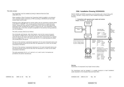
The entity concept.<br />
The Transmitter must be installed according to National Electrical Code<br />
(ANSI-NFPA 70).<br />
When installed in Class II locations the Transmitter shall be installed in an enclosure<br />
with a specified ingress protections of IP6X according to IEC60529 and Dust-tight<br />
conduit seals must be used.<br />
Equipment that is FM-approved for intrinsic safety may be connected to barriers based<br />
on the ENTITY CONCEPT. This concept permits interconnection of approved transmitters,<br />
meters and other devices in combinations which have not been specifically<br />
examined by FM, provided that the agency's criteria are met. The combination is then<br />
intrinsically safe, if the entity concept is acceptable to the authority having jurisdiction<br />
over the installation.<br />
The entity concept criteria are as follows:<br />
The intrinsically safe devices, other than barriers, must not be a source of power.<br />
The maximum voltage Ui(VMAX) and current Ii(IMAX), and maximum power Pi(Pmax),<br />
which the device can receive and remain intrinsically safe, must be equal to or greater<br />
than the voltage (Uo or VOC or Vt) and current (Io or ISC or It) and the power Po which<br />
can be delivered by the barrier.<br />
The sum of the maximum unprotected capacitance (Ci) for each intrinsically device and<br />
the interconnecting wiring must be less than the capacitance (Ca) which can be safely<br />
connected to the barrier.<br />
The sum of the maximum unprotected inductance (Li) for each intrinsically device and<br />
the interconnecting wiring must be less than the inductance (La) which can be safely<br />
connected to the barrier.<br />
The entity parameters Uo,VOC or Vt and Io,ISC or It, and Ca and La for barriers are<br />
provided by the barrier manufacturer.<br />
5300Q502.doc 2005-12-16 Rev. AD 2/2<br />
CSA Installation Drawing 533XQC03.<br />
5331D, 5333D and 5335D transmitters are intrinsically safe in Zone 0 Group IIC<br />
or Class I, Division1, Group A,B,C,D when installed according to Installation<br />
Drawing.<br />
1. Connections with separate power supply and receiver.<br />
Output: Standard 4 – 20 mA loop<br />
Separate Power<br />
Supply<br />
Ambient temperature limits<br />
T4:-40 to + 85 deg. Celcius<br />
T6:-40 to + 60 deg. Celcius<br />
Receiving<br />
Instrument<br />
533XQC03.DOC 2006-01-04 Rev. AB 1/2<br />
<strong>5333V</strong>110 53333V110<br />
-<br />
+<br />
- +<br />
CSA approved<br />
Barrier<br />
+<br />
1 2<br />
6<br />
5<br />
-<br />
SENSOR<br />
5331D or<br />
5333D or<br />
5335D<br />
5331D or<br />
5333D<br />
3<br />
4 5335D<br />
Warning:<br />
Substitution of components may impair intrinsic safety.<br />
Intrinsically safe<br />
Barrier Parameters.<br />
Uo(Voc) =< 30 V<br />
Io(Isc) =< 120 mA<br />
Po =< 0.84 W<br />
Co(Ca)>Sum(Ci+Ccable)<br />
Lo(La)>Sum(Li+Lcable)<br />
Terminal: 1-2<br />
Ui(Vmax) = 30 V<br />
Ii(Imax) = 120 mA<br />
Pi = 0.84 W<br />
Ci = 1 nF<br />
Li = 10 uH<br />
Terminal: 3,4,5,6<br />
Only passive, or non-energy<br />
storing devices such as<br />
RTD's and Thermocouples<br />
may be connected.<br />
Terminal: 3,4,5,6<br />
Uo(Voc) = 9.6 V<br />
Io(Isc) = 28 mA<br />
Po = 67.2 mW<br />
Co(Ca) = 3.5 uF<br />
Lo(La) = 35 mH<br />
Non<br />
hazardous<br />
Location<br />
max. 250 V<br />
Hazardous<br />
Locations /<br />
Sécurité<br />
Intrinséque<br />
The transmitters must be installed in a suitable enclosure to meet installation<br />
codes stipulated in the Canadian Electrical Code (CEC).
![Bedienungsanleitung Typ BA_8627_8628_8632_DE [PDF, 459 KB]](https://img.yumpu.com/23348412/1/184x260/bedienungsanleitung-typ-ba-8627-8628-8632-de-pdf-459-kb.jpg?quality=85)
![Bedienungsanleitung_Typ BA_optris CT LT_DE [PDF, 4.00 MB]](https://img.yumpu.com/22293726/1/190x133/bedienungsanleitung-typ-ba-optris-ct-lt-de-pdf-400-mb.jpg?quality=85)
![Komplettes Datenblatt Typ 8821_DE [PDF, 499 KB] - MTS ...](https://img.yumpu.com/21876808/1/184x260/komplettes-datenblatt-typ-8821-de-pdf-499-kb-mts-.jpg?quality=85)
![Komplettes Datenblatt Typ 1440_DE [PDF, 524 KB] - MTS ...](https://img.yumpu.com/21876799/1/184x260/komplettes-datenblatt-typ-1440-de-pdf-524-kb-mts-.jpg?quality=85)


![Komplettes Datenblatt Typ 8411_DE [PDF, 459 KB] - MTS ...](https://img.yumpu.com/20642872/1/184x260/komplettes-datenblatt-typ-8411-de-pdf-459-kb-mts-.jpg?quality=85)

![Manual CT13 Serie [PDF, 1.00 MB] - MTS Messtechnik ...](https://img.yumpu.com/20620646/1/184x260/manual-ct13-serie-pdf-100-mb-mts-messtechnik-.jpg?quality=85)
![Komplettes Datenblatt Typ 4503A_DE [PDF, 795 KB] - MTS ...](https://img.yumpu.com/20620634/1/184x260/komplettes-datenblatt-typ-4503a-de-pdf-795-kb-mts-.jpg?quality=85)

![Prüfstandssysteme [PDF, 2.00 MB] - MTS Messtechnik Schaffhausen ...](https://img.yumpu.com/18883102/1/184x260/prufstandssysteme-pdf-200-mb-mts-messtechnik-schaffhausen-.jpg?quality=85)