The manual for the Datalogger ECOLOG-NET LA8 - Elpro
The manual for the Datalogger ECOLOG-NET LA8 - Elpro
The manual for the Datalogger ECOLOG-NET LA8 - Elpro

You also want an ePaper? Increase the reach of your titles
YUMPU automatically turns print PDFs into web optimized ePapers that Google loves.
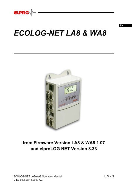
<strong>ECOLOG</strong>-<strong>NET</strong> <strong>LA8</strong> & WA8<br />
from Firmware Version <strong>LA8</strong> & WA8 1.07<br />
and elproLOG <strong>NET</strong> Version 3.33<br />
<strong>ECOLOG</strong>-<strong>NET</strong> <strong>LA8</strong>/WA8 Operation Manual<br />
D-EL-6005Ec 11.2009 AG<br />
EN - 1<br />
DE<br />
EN<br />
FR<br />
IT<br />
QLS
Table of contents<br />
1. Product description ............................................................................ 4<br />
2. General application and safety in<strong>for</strong>mation ................................... 6<br />
3. Configuring <strong>the</strong> datalogger <strong>for</strong> <strong>the</strong> network................................. 14<br />
4. Settings in elproLOG ANALYZE ..................................................... 16<br />
5. Defining threshold values and alarm parameters ....................... 20<br />
6. Menu .................................................................................................... 22<br />
7. Functions of collective alarm contact ........................................... 24<br />
8. Pin assignment and connectors..................................................... 25<br />
9. Alarm diagrams ................................................................................. 28<br />
10. Status and error codes..................................................................... 29<br />
11. Transmitters ....................................................................................... 30<br />
11.1Temperature with PT100.................................................................. 30<br />
11.2Humidity .......................................................................................... 31<br />
11.3Pressure.......................................................................................... 32<br />
11.4Differential Pressure ........................................................................ 33<br />
11.5CO2 ................................................................................................ 34<br />
12. General in<strong>for</strong>mation.......................................................................... 35<br />
12.1Measuring range, operating range and accuracy .................................35<br />
12.2Viewing ranges .....................................................................................35<br />
13.3Aaccessories ........................................................................................36<br />
12.4Dimensional drawing ............................................................................37<br />
12.5Revision history ............................................................................... 37<br />
Index ..........................................................................................................38<br />
In <strong>the</strong> interest of our customers, we reserve <strong>the</strong> right to per<strong>for</strong>m alterations resulting<br />
from subsequent technical developments without any particular notice. For<br />
this reason, diagrams, descriptions and in<strong>for</strong>mation concerning <strong>the</strong> scope of<br />
delivery are not binding!<br />
This <strong>manual</strong> is valid from firmware version 1.07 and elproLOG 3.33<br />
2 - EN <strong>ECOLOG</strong>-<strong>NET</strong> <strong>LA8</strong>/WA8 Operation Manual<br />
D-EL-6005Ec 11.2009 AG
Used symbols & identification codes<br />
Symbols<br />
�<br />
IMPORTANT INFORMATION, WARNING<br />
Note<br />
Cross reference to related chapter or document<br />
Identification code<br />
Network Logger Part No. Abbreviation & special chapter<br />
LAN <strong>LA8</strong> 2720 ...A8<br />
LAN-PoE 12VDC <strong>LA8</strong> 2720 & 2730-A ...A8 & � 2.8 Power over E<strong>the</strong>rnet<br />
LAN-PoE 24VDC <strong>LA8</strong> 2720 & 2730-B ...A8 & � 2.8 Power over E<strong>the</strong>rnet<br />
WLAN WA8 2722 ....A8<br />
Evaluation software Identification in this document<br />
elproLOG ANALYZE elproLOG ANALYZE<br />
elproLOG ANALYZE-QLS elproLOG ANALYZE<br />
For a detailed description see elproLOG ANALYZE operation <strong>manual</strong> (SE3003E) and<br />
software OnLine help.<br />
<strong>ECOLOG</strong>-<strong>NET</strong> <strong>LA8</strong>/WA8 Operation Manual<br />
D-EL-6005Ec 11.2009 AG<br />
EN - 3<br />
DE<br />
EN<br />
FR<br />
IT<br />
QLS
Product description<br />
1. Product description<br />
8-channel<br />
4-20mA<br />
64,000 data points<br />
UPS �<br />
1.1 <strong>Datalogger</strong><br />
Connections<br />
Key pad<br />
Battery protection<br />
Removal of this slip causes<br />
<strong>the</strong> first "System<br />
Reset" entry in <strong>the</strong> datalogger<br />
status!<br />
Wait 10s after <strong>the</strong> battery<br />
protection has<br />
been removed till <strong>the</strong><br />
datalogger is operable �<br />
<strong>ECOLOG</strong>-<strong>NET</strong> <strong>LA8</strong> & WA8 dataloggers are network-compatible<br />
(LAN or WLAN) 8-channel dataloggers with a capacity<br />
<strong>for</strong> recording 64,000 data points. 4-20mA signals can be collected.<br />
<strong>The</strong> data are loaded to <strong>the</strong> PC via local network.<br />
Even in <strong>the</strong> event of a power failure, all <strong>the</strong> logged data is<br />
retained and <strong>the</strong> internal clock keeps running. If <strong>the</strong> sensor<br />
power supply should be available during a power failure,<br />
<strong>the</strong>n <strong>the</strong> datalogger power supply unit must be fed with 115/<br />
230VAC by an UPS (uninterruptable power supply). <strong>The</strong>re<br />
are various alarm features provided by <strong>the</strong> local alarm contacts<br />
and <strong>the</strong> network functions.<br />
<strong>The</strong> <strong>ECOLOG</strong>-<strong>NET</strong> <strong>LA8</strong> & WA8 has a number of connetion<br />
points at <strong>the</strong> left side of its casing. <strong>The</strong> front side has a display<br />
and a key pad.<br />
Fig. 1<br />
1. Network connection<br />
2. 8 x 4...20mA input<br />
3. USB connection<br />
4. Power supply, digital inputs & alarm output<br />
5. Alarm output<br />
6. Key pad with 4 buttons<br />
7. Type label with ID number and IP address<br />
8. Battery<br />
9. Battery protection<br />
4 - EN <strong>ECOLOG</strong>-<strong>NET</strong> <strong>LA8</strong>/WA8 Operation Manual<br />
D-EL-6005Ec 11.2009 AG
1.2 Display<br />
Fig. 2<br />
1. Measured value with unit of measurement and 4 userdefinable<br />
units of measurement at<br />
1.1, 1.2, 1.3 and 1.4, ( 4.1.4 Axis Assignment)<br />
2. Date or communication � via USB or LAN connection<br />
3. Time<br />
4. Alarm<br />
5. Measured value above upper threshold value<br />
6. Measured value below lower threshold value<br />
7. Sensor number<br />
8. Alarm from sensor 1...8<br />
9. Data logging running<br />
10. Battery low ( 2.5 Battery back-up / lifetime)<br />
�<br />
1.3 Technical alterations - CE - WEEE<br />
In <strong>the</strong> interest of our customers, we reserve <strong>the</strong> right to per<strong>for</strong>m<br />
alterations resulting from subsequent technical<br />
developments without any particular notice. For this reason,<br />
diagrams, descriptions and in<strong>for</strong>mation concerning <strong>the</strong><br />
scope of delivery are not binding!<br />
- This product must be certified with CE.<br />
- <strong>The</strong> manufacturer guarantees that this product<br />
complies with <strong>the</strong> relevant guidelines:<br />
EN 61000-6-2 : 2001 and EN 61000-6-4 : 2001<br />
- Waste treatment of this product has to comply<br />
with WEEE (Waste electrical and electronic<br />
equipment, 2002/96/EC)!<br />
<strong>ECOLOG</strong>-<strong>NET</strong> <strong>LA8</strong>/WA8 Operation Manual<br />
D-EL-6005Ec 11.2009 AG<br />
Product description<br />
Large LCD display <strong>for</strong><br />
measured values, unit<br />
of measurement and<br />
states �<br />
EN - 5<br />
DE<br />
EN<br />
FR<br />
IT<br />
QLS
General application and safety in<strong>for</strong>mation<br />
2. General application and safety in<strong>for</strong>mation<br />
2.1 Communication<br />
USB connection<br />
LAN connection �<br />
2.2 Influence of temperature<br />
<strong>The</strong> <strong>ECOLOG</strong>-<strong>NET</strong> family of dataloggers are fitted with a 10/<br />
100 Base T network connection point. All logger functions<br />
and network configurations can be executed via this connection.<br />
Additionally, <strong>the</strong> dataloggers have a USB connection point.<br />
This connection can be used to set dataloggers parameters<br />
and to per<strong>for</strong>m data readouts if no network connection is<br />
available. However, it can not be used to define network<br />
parameters. Data exchange via LAN is not possible when<br />
both connection points are occupied.<br />
<strong>The</strong> datalogger requires an external power supply to operate<br />
<strong>The</strong> LAN interface. After connecting <strong>the</strong> power supply, it<br />
takes approx. 1 minute until <strong>the</strong> datalogger is addressable<br />
via <strong>the</strong> LAN.<br />
Proceed as follows to achieve a trouble-free USB connection:<br />
1. Connect <strong>the</strong> power supply to <strong>the</strong> datalogger and switch<br />
on <strong>the</strong> PC<br />
2. Do not connect <strong>the</strong> USB cable until both units are ready<br />
<strong>for</strong> operation<br />
3. <strong>The</strong> Windows driver relevant <strong>for</strong> <strong>the</strong> implemented USB<br />
connection must be installed. If a suitable driver is not<br />
available, use <strong>the</strong> elproLOG ANALYZE software CD to<br />
install one.<br />
4. elproLOG ANALYZE: options - connection options -<br />
RS232 & 57600 (Hoseries 4) & appropriate COM-port.<br />
- For <strong>the</strong> range of application, 12.1 Measuring<br />
range, Operating range and accuracy. �<br />
- It can not be guaranteed that <strong>the</strong> loggers will function<br />
properly at temperatures outside <strong>the</strong> specified threshold<br />
range. Experience has shown that <strong>the</strong> battery freezes at<br />
approx. -50°C, that it is no longer possible to per<strong>for</strong>m<br />
measurements and that <strong>the</strong> timer tracking function can<br />
be temporarily interrupted. To make fur<strong>the</strong>r operation<br />
possible, <strong>the</strong> logger must be reprogrammed when room<br />
temperature is reestablished.<br />
6 - EN <strong>ECOLOG</strong>-<strong>NET</strong> <strong>LA8</strong>/WA8 Operation Manual<br />
D-EL-6005Ec 11.2009 AG
- <strong>The</strong> legibility of <strong>the</strong> display is impaired when temperatures<br />
fall below - 20°C. However, long-term use does<br />
not present any problems.<br />
- Lithium battery passivation, due to long-term use at<br />
temperatures exceeding 40°C, can result in temporary<br />
read problems (self-discharge protection). Per<strong>for</strong>m<br />
repeated evaluation to rectify this problem.<br />
- Battery self-discharging increases at temperatures<br />
exceeding 45°C and continuous operation at temperatures<br />
above 45°C can reduce battery lifetime by approx.<br />
1/3.<br />
- Exposure to temperatures exceeding 55°C can result in<br />
permanent discoloration of <strong>the</strong> display.<br />
- <strong>The</strong>re is danger of a gas explosion when <strong>the</strong> lithium<br />
battery heats up to temperatures exceeding 100°C.<br />
<strong>ECOLOG</strong>-<strong>NET</strong> <strong>LA8</strong>/WA8 Operation Manual<br />
D-EL-6005Ec 11.2009 AG<br />
General application and safety in<strong>for</strong>mation<br />
2.3 Exceptional environmental conditions<br />
Pay attention to <strong>the</strong> following when dataloggers are used<br />
under exceptional environmental conditions:<br />
- IR radiation (heat) and superheated steam can damage<br />
<strong>the</strong> surface coating on <strong>the</strong> casing<br />
- <strong>The</strong>re is a risk that <strong>the</strong> battery may explode if <strong>the</strong> logger<br />
is used in conjunction with microwaves<br />
THE DATALOGGER MUST BE AT ROOM TEMPE-<br />
RATURE PRIOR INITIAL STARTUP!<br />
Initial startup �<br />
2.4 Precautionary measures <strong>for</strong> handling units containing<br />
lithium batteries<br />
- Do not short-circuit and charge batteries: explosion<br />
hazard<br />
- Do not throw units which contain batteries into fire:<br />
explosion hazard<br />
- Do not subject batteries to mechanical stress and do not<br />
dismantle <strong>the</strong>m. <strong>The</strong> leaking battery fluid is highly corrosive<br />
and lithium can generate severe heat when it<br />
comes into contact with moisture or it can ignite fire.<br />
- Do not heat up battery-driven units to temperatures<br />
exceeding 100°C: explosion hazard<br />
- Avoid violent knocks and blows<br />
Lithium batteries �<br />
EN - 7<br />
DE<br />
EN<br />
FR<br />
IT<br />
QLS
General application and safety in<strong>for</strong>mation<br />
2.5 Battery back-up / lifetime<br />
Battery lifetime<br />
Power-save mode �<br />
- Follow <strong>the</strong> manufacturer specifications <strong>for</strong> storing batteries<br />
- Return batteries to <strong>the</strong> supplier <strong>for</strong> correct waste<br />
disposal<br />
...A8<br />
Battery low<br />
2.6 Logger display / Power-save mode<br />
Battery lifetime of approx. 3 months <strong>for</strong> <strong>the</strong><br />
current datalogger version in <strong>the</strong> event of a<br />
total power failure (back-up).<br />
This indicator ( � 1.2 Display) is activated<br />
when <strong>the</strong> battery capacity limit is reached.<br />
Replace <strong>the</strong> battery at <strong>the</strong> next possible opportunity<br />
in accordance with <strong>the</strong> instructions in<br />
( � 2.11 Maintenance).<br />
<strong>The</strong> <strong>ECOLOG</strong>-<strong>NET</strong> datalogger has a power-save mode<br />
which switches off <strong>the</strong> display. As a result, measurements<br />
are only made during <strong>the</strong> defined log interval. 4 small circles<br />
located in <strong>the</strong> display indicate that <strong>the</strong> datalogger is<br />
functioning and recording correctly.<br />
<strong>The</strong> elproLOG ANALYZE software (Extended Setup - Display<br />
mode / Powersave) switches <strong>the</strong> power-save mode on<br />
an off. ...A8 datalogger types go automatically into powersave<br />
mode when no external power supply is available. If<br />
you need to make a check, use <strong>the</strong> keypad to switch on <strong>the</strong><br />
display temporarily.<br />
2.7 Threshold values function / Alarm conditions<br />
<strong>ECOLOG</strong>-<strong>NET</strong> ...A8 dataloggers have a feature <strong>for</strong> monitoring<br />
threshold values. <strong>The</strong> threshold values are defined<br />
separately <strong>for</strong> each individual sensor 5. Defining threshold<br />
values and alarm parameters. �<br />
<strong>The</strong> <strong>ECOLOG</strong>-<strong>NET</strong> can signal a threshold violation in<br />
various ways:<br />
Threshold violation � 1. A threshold violation is shown on <strong>the</strong> display; signaling<br />
is always sensor-specific. Both arrowheads indicate a<br />
threshold violation 1.2 Display. <strong>The</strong>y are visible <strong>for</strong><br />
�<br />
8 - EN <strong>ECOLOG</strong>-<strong>NET</strong> <strong>LA8</strong>/WA8 Operation Manual<br />
D-EL-6005Ec 11.2009 AG
<strong>the</strong> actual duration of <strong>the</strong> threshold violation only. This<br />
status is not logged.<br />
2. ALARM is displayed when <strong>the</strong> conditions <strong>for</strong> an alarm<br />
are fulfilled. It is dependent on <strong>the</strong> selected alarm output<br />
(self-sustaining)<br />
3. In <strong>the</strong> case of an alarm being triggered, <strong>the</strong> <strong>ECOLOG</strong>-<br />
<strong>NET</strong> has a collective alarm function. This function is<br />
activated simultaneously at <strong>the</strong> time <strong>the</strong> text ALARM is<br />
displayed. 7. Functions of collective alarm contact<br />
& 9. Alarm �diagrams. 4. After <strong>the</strong> alarm delay time, an alarm is not registered in<br />
<strong>the</strong> memory until <strong>the</strong> subsequent log interval has<br />
elapsed. All threshold violations / alarms are registered<br />
in <strong>the</strong> alarm protocol, even when <strong>the</strong>y are shorter than<br />
<strong>the</strong> defined log interval!<br />
Use <strong>the</strong> PC software or <strong>the</strong> keypad to acknowledge alarm<br />
messages.<br />
DURING NORMAL OPERATION, THE THRES-<br />
HOLD VALUES ARE CHECKED EVERY 4<br />
SECONDS OR AT THE DEFINED LOG INTERVAL<br />
IF A SHORTER TIME HAS BEEN SET.<br />
IN POWER-SAVE MODE, THRESHOLD VALUES<br />
ARE MONITORED EITHER IN 1 MINUTE CYCLES<br />
IF THE LOG INTERVAL IS LONGER THAN 1<br />
MINUTE OR AT THE DEFINED LOG INTERVAL IF<br />
SHORTER INTERVALS HAVE BEEN SET. THE<br />
FOLLOWING TEXT IS DISPLAYED WHEN THE<br />
CONDITIONS FOR AN ALARM ARE FULFILLED IN<br />
POWER-SAVE MODE: ALARM AND, IN ADDITION,<br />
ALA.<br />
THRESHOLD VALUES ARE NOT MONITORED<br />
WHEN THE LOGGER IS IN STOP MODE.<br />
<strong>ECOLOG</strong>-<strong>NET</strong> <strong>LA8</strong>/WA8 Operation Manual<br />
D-EL-6005Ec 11.2009 AG<br />
General application and safety in<strong>for</strong>mation<br />
Acknowledging alarm<br />
messages �<br />
Monitoring thresholds<br />
values during normal or<br />
power-save mode �<br />
EN - 9<br />
DE<br />
EN<br />
FR<br />
IT<br />
QLS
General application and safety in<strong>for</strong>mation<br />
1<br />
2<br />
3<br />
4<br />
2.7.1 Timing Collective Alarm<br />
Alarm is shorter than <strong>the</strong> datalogger recording interval<br />
<strong>ECOLOG</strong>-<strong>NET</strong> Alarm contact reacts immediately.<br />
ANALYZE<br />
MONITOR<br />
Alarm logged<br />
No alarm measurement, because <strong>the</strong> alarm is shorter than<br />
<strong>the</strong> log interval, alarm protocol with 2 entries - alarm on/off.<br />
Represents an alarm <strong>for</strong> 1 cycle time.<br />
Alarm status is up-dated at <strong>the</strong> end of a cycle time.<br />
<strong>ECOLOG</strong>-<strong>NET</strong> Alarm contact reacts immediately<br />
ANALYZE<br />
MONITOR<br />
2 alarm measurements, alarm protocol with 2 entries - alarm<br />
on/off.<br />
Represents an alarm over 7 cycle times.<br />
Alarm with self-sustaining; logged<br />
<strong>ECOLOG</strong>-<strong>NET</strong> Alarm contact reacts immediately.<br />
ANALYZE<br />
MONITOR<br />
Alarm with delay time; logged<br />
1 alarm measurement, alarm protocol with 2 or 3 entries -<br />
alarm on/off/(quit ...P4 only).<br />
Represents an alarm till <strong>the</strong> end of <strong>the</strong> limit value violation (5<br />
cycle times). <strong>The</strong> duration of <strong>the</strong> self-sustaining period is not<br />
represented as alarm.<br />
<strong>ECOLOG</strong>-<strong>NET</strong> Alarm contact reacts after <strong>the</strong> delay time has elapsed.<br />
ANALYZE<br />
MONITOR<br />
1 alarm measurement, alarm protocol with 2 entries - alarm<br />
on/off. „Alarm on“ is logged after delay time has elapsed.<br />
Represents an alarm over 3 cycle times. <strong>The</strong> end of <strong>the</strong> third<br />
cycle falls already into a new, delayed alarm, <strong>the</strong>re<strong>for</strong>e it wont<br />
be recognized as alarm..<br />
10 - EN <strong>ECOLOG</strong>-<strong>NET</strong> <strong>LA8</strong>/WA8 Operation Manual<br />
D-EL-6005Ec 11.2009 AG
5<br />
6<br />
2.8 Power over E<strong>the</strong>rnet<br />
<strong>ECOLOG</strong>-<strong>NET</strong> <strong>LA8</strong> dataloggers can be equipped with an<br />
additional PoE module. This option means that <strong>the</strong> datalogger<br />
can be operated without any additional external power<br />
supply unit. Pay attention to <strong>the</strong> following <strong>for</strong> datalogger operation<br />
with a switch that supports <strong>the</strong> PoE option:<br />
- <strong>The</strong> datalogger supports standard IEEE 802.3 af<br />
(phantom supply not supported)<br />
- PoE does not work on a Gigabit-E<strong>the</strong>rnet LAN<br />
- <strong>The</strong> following diagram (Fig. 3) shows <strong>the</strong> pin assignment<br />
<strong>for</strong> <strong>the</strong> RJ45 connector in accordance with IEEE<br />
802.3 af with spare pairs. <strong>The</strong> coloring coding complies<br />
with T568B:<br />
1<br />
2<br />
3<br />
4<br />
5<br />
6<br />
7<br />
8<br />
orange / white<br />
orange<br />
green / white<br />
blue<br />
blue / white<br />
green<br />
brown / white<br />
brown<br />
Fig .3<br />
<strong>ECOLOG</strong>-<strong>NET</strong> <strong>LA8</strong>/WA8 Operation Manual<br />
D-EL-6005Ec 11.2009 AG<br />
General application and safety in<strong>for</strong>mation<br />
RESET of delay time by short limit value violations<br />
<strong>ECOLOG</strong>-<strong>NET</strong><br />
ANALYZE<br />
Alarm contact does not react. Even repeated, short limit value<br />
violations do not lead to logged alarms, <strong>the</strong> delay time starts<br />
from <strong>the</strong> beginning at each new limit value violation.<br />
No alarm measurement, alarm protocol with no entries.<br />
MONITOR Does not represent an alarm<br />
Alarm with time delay; not logged<br />
<strong>ECOLOG</strong>-<strong>NET</strong><br />
ANALYZE<br />
Alarm contact reacts after <strong>the</strong> delay time has elapsed.<br />
No alarm measurement, alarm protocol with 2 entries - alarm<br />
on/off<br />
MONITOR Represents an alarm over 2 cycle times<br />
RX+<br />
RX-<br />
TX+<br />
V+<br />
V+<br />
TX-<br />
V-<br />
V-<br />
PoE<br />
Part No. 2370<br />
A green LED on <strong>the</strong> PoE<br />
module (inside of <strong>the</strong><br />
housing back plane)<br />
shows <strong>the</strong> functioning of<br />
<strong>the</strong> PoE module. �<br />
EN - 11<br />
DE<br />
EN<br />
FR<br />
IT<br />
QLS
General application and safety in<strong>for</strong>mation<br />
2.9 elproLOG ANALYZE Function: Overlaying<br />
2.10 Digital Inputs D1 and D2<br />
Function Possible Configuration<br />
Time stamp D2 Key D2 Key<br />
At present, mutual overlaying is not available <strong>for</strong> dataloggers<br />
<strong>LA8</strong> / WA8.<br />
Both inputs are occupied with dual functions!<br />
In each case one function should be used only<br />
Defrost on D1 external D1 external<br />
Alarm <strong>for</strong>warding D1 external D2 external # D1 external; D2 external #<br />
D2 Key See function F2, time stamp indicate as D2 6. Menu � This function can be used to register incidents (e.g. a watchman's patrol)<br />
at <strong>the</strong> logger.<br />
D1 external Defrost on ( � 5. Defining threshold values and alarm parameters) or <strong>for</strong><br />
alarm <strong>for</strong>warding. � 8.3 Socket 7; DB9; male<br />
# Alarm <strong>for</strong>warding � 8.3 Socket 7; DB9; male<br />
- Status of D1 and D2 are not documented in <strong>the</strong> alarm<br />
protocl and <strong>the</strong>y do not influence <strong>the</strong> alarm switches.<br />
<strong>The</strong>se inputs are show in <strong>the</strong> evaluation software<br />
elproLOG ANALYZE, measurement table as D1, D2 or<br />
MarkPos.<br />
Alarm <strong>for</strong>warding � - Alarm <strong>for</strong>warding is used by <strong>the</strong> elproLOG MONITOR<br />
software. <strong>The</strong> status (Alarm / no Alarm) of both inputs<br />
will be checked during <strong>the</strong> up-date of <strong>the</strong> elproLOG<br />
MONITOR data. A status change between two up-dates<br />
wont be detected.<br />
12 - EN <strong>ECOLOG</strong>-<strong>NET</strong> <strong>LA8</strong>/WA8 Operation Manual<br />
D-EL-6005Ec 11.2009 AG
2.11 Maintenance<br />
To ensure proper datalogger functioning, <strong>the</strong> following steps<br />
should be part of a periodic maintenance schedule:<br />
- Calibrate <strong>the</strong> datalogger<br />
- Per<strong>for</strong>m datalogger readout and save <strong>the</strong> data; test <strong>the</strong><br />
alarm function, if implemented<br />
- Replace <strong>the</strong> battery 12.4 Dimensional drawing<br />
(Part No. 2820, set of �2, storable <strong>for</strong> at least 5 years /<br />
lithium 3.6V, 1900mAh, AM3/LR6/AA)<br />
An energy consumption count is used to monitor datalogger<br />
battery life. For this reason, only <strong>the</strong> specific manufacturerrecommended<br />
battery should be used. Do not remove <strong>the</strong><br />
battery from <strong>the</strong> logger when it is not in use. <strong>The</strong> use of o<strong>the</strong>r<br />
batteries or removal of batteries will produce incorrect status<br />
in<strong>for</strong>mation at <strong>the</strong> battery indicator.<br />
RESET THE BATTERY CHANGE TIME AFTER YOU<br />
REPLACE THE BATTERY (ELPROLOG ANALYZE<br />
SOFTWARE - EXTENDED SETUP - PRO-<br />
GRAMMING BATTERY CHANGE TIME...) OTHER-<br />
WISE THE ENERGY COUNTER WILL NOT<br />
FUNCTION CORRECTLY!<br />
<strong>ECOLOG</strong>-<strong>NET</strong> <strong>LA8</strong>/WA8 Operation Manual<br />
D-EL-6005Ec 11.2009 AG<br />
General application and safety in<strong>for</strong>mation<br />
Maintenanceschedule<br />
�<br />
Battery �<br />
Replacing battery �<br />
EN - 13<br />
DE<br />
EN<br />
FR<br />
IT<br />
QLS
Configuring <strong>the</strong> datalogger <strong>for</strong> <strong>the</strong> network<br />
3. Configuring <strong>the</strong> datalogger <strong>for</strong> <strong>the</strong> network<br />
elproLOG ANALYZE<br />
elproLOG MONITOR<br />
Digi Device Discovery �<br />
3.1 Desktop installation<br />
Service <strong>manual</strong>:<br />
www.elpro.com/Download/Data<br />
sheets/ECO-<br />
LOG-<strong>NET</strong> networkable<br />
datalogger/<strong>ECOLOG</strong>-<br />
<strong>NET</strong> service <strong>manual</strong><br />
IT6001A. �<br />
For datalogger identification within a network environment,<br />
an unambiguous network address is assigned to each datalogger.<br />
This address is made up of 3 different types of in<strong>for</strong>mation:<br />
IP address, sublet mask and default gateway. We<br />
recommend <strong>the</strong> use of a fix IP address <strong>for</strong> programs elpro-<br />
LOG ANALYZE & elproLOG MONITOR.<br />
To avoid network conflicts, <strong>the</strong> network administrator should<br />
allocate <strong>the</strong> network address! <strong>The</strong> 3 types of address in<strong>for</strong>mation<br />
must be entered <strong>manual</strong>ly at every datalogger with<br />
<strong>the</strong> help of software: Digi Device Discovery.<br />
<strong>The</strong> relevant network address is assigned to <strong>the</strong> datalogger<br />
during this workstep. This work should be per<strong>for</strong>med at <strong>the</strong><br />
place of use prior to final installation, e.g. in an office.<br />
3.1.1 Communication test<br />
Check <strong>the</strong> network configuration and per<strong>for</strong>m a functional<br />
communication test<br />
3.1.2 Documentation<br />
Document <strong>the</strong> per<strong>for</strong>med configuration. Keep a written<br />
record of <strong>the</strong> network parameters on a status printout from<br />
<strong>the</strong> datalogger and...<br />
..make a note of <strong>the</strong> IP address on <strong>the</strong> datalogger type<br />
label. This is <strong>the</strong> simplest way to identify <strong>the</strong> datalogger<br />
during installation!<br />
3.1.3 Additional settings <strong>for</strong> <strong>ECOLOG</strong>-<strong>NET</strong> WLAN<br />
SSID, channel, encryption<br />
<strong>ECOLOG</strong>-<strong>NET</strong> service <strong>manual</strong><br />
� For any fur<strong>the</strong>r details concerning a WLAN installation, see<br />
your local network documentation please.<br />
14 - EN <strong>ECOLOG</strong>-<strong>NET</strong> <strong>LA8</strong>/WA8 Operation Manual<br />
D-EL-6005Ec 11.2009 AG
3.2 Installing <strong>the</strong> datalogger<br />
3.2.1 Installation<br />
Mount <strong>the</strong> datalogger at <strong>the</strong> place of use in accordance with<br />
<strong>the</strong> network plan and connect <strong>the</strong> sensor probes.<br />
3.2.2 Communication test<br />
Check communication - PING<br />
3.2.3 elproLOG CONFIG<br />
This software is used <strong>for</strong> organizing <strong>the</strong> dataloggers within<br />
<strong>the</strong> network environment. <strong>The</strong> dataloggers can be grouped<br />
toge<strong>the</strong>r within <strong>the</strong> network to <strong>for</strong>m groups or logic units.<br />
Both elproLOG ANALYZE and elproLOG MONITOR work<br />
with this in<strong>for</strong>mation. For more in<strong>for</strong>mation about using this<br />
software, � SC3001E.<br />
3.2.4 elproLOG ANALYZE<br />
Set <strong>the</strong> datalogger parameters, � 4. Settings in elproLOG<br />
ANALYZE and 5. Defining threshold values and alarm parameters.<br />
<strong>The</strong> <strong>ECOLOG</strong>-<strong>NET</strong> <strong>LA8</strong> & WA8 have 8 measuring channels.<br />
Any 4 of <strong>the</strong>se 8 channels can be viewed with <strong>the</strong> elproLOG<br />
ANALYZE software at one time � 4.1.1 Procedure <strong>for</strong><br />
first setup.<br />
3.2.5 elproLOG MONITOR<br />
This program is used <strong>for</strong> online viewing of measured values.<br />
For a detailed description of <strong>the</strong> functions and applications,<br />
� SM3001E.<br />
3.2.6 Installation verification<br />
Check <strong>the</strong> installation and make sure that <strong>the</strong> sensor positions,<br />
alarm parameters and network address are correct. To<br />
help, use auxiliary devices (e.g. calibration connector) to<br />
simulate defined measured values.<br />
<strong>ECOLOG</strong>-<strong>NET</strong> <strong>LA8</strong>/WA8 Operation Manual<br />
D-EL-6005Ec 11.2009 AG<br />
Configuring <strong>the</strong> datalogger <strong>for</strong> <strong>the</strong> network<br />
elproLOG CONFIG �<br />
elproLOG ANA-<br />
LYZE �<br />
elproLOG MONI-<br />
TOR �<br />
EN - 15<br />
DE<br />
EN<br />
FR<br />
IT<br />
QLS
Settings in elproLOG ANALYZE<br />
4. Settings in elproLOG ANALYZE<br />
4.1 <strong>Datalogger</strong> setup<br />
<strong>Datalogger</strong> setup �<br />
Window "<strong>Datalogger</strong> Setup" is used to define <strong>the</strong><br />
implemented measuring parameters.<br />
- Mode<br />
- Log Start<br />
- Log Interval<br />
- Module Tag<br />
- Close, Reprogram<br />
4.1.1 Procedure <strong>for</strong> first setup<br />
For easy setup of <strong>the</strong> datalogger we recommend <strong>the</strong> following<br />
procedure:<br />
1. Define sensor profiles 4.1.3 Sensor Profiles<br />
2. <strong>Datalogger</strong> setup �<br />
3. Proceed with assignment according 4.1.4 Axis<br />
Assignment �<br />
16 - EN <strong>ECOLOG</strong>-<strong>NET</strong> <strong>LA8</strong>/WA8 Operation Manual<br />
D-EL-6005Ec 11.2009 AG
4.1.2 Sensors<br />
1. Sensor number S1 ... S8<br />
2. Check box to select measuring channel<br />
3. User-defined name <strong>for</strong> measuring channel<br />
4. Measurement range selection. One of <strong>the</strong> 8 predefined<br />
measurement ranges can be assigned to <strong>the</strong> measuring<br />
channel.<br />
5. Opens <strong>the</strong> window used to set <strong>the</strong> parameters <strong>for</strong> <strong>the</strong> 8<br />
possible measurement ranges � 4.1.3 Sensor Profiles<br />
6. Opens <strong>the</strong> window used to map <strong>the</strong> channels to <strong>the</strong> 4<br />
axes of <strong>the</strong> displayable elproLOG graphics � 4.1.4<br />
Axis Assignment<br />
4.1.3 Sensor Profiles<br />
1. By selecting a channel, it is possible to define range and<br />
unit � see point 2 - 6<br />
2. Menu to select <strong>the</strong> display unit.<br />
Units of measurements °C, °F and %rH are shown on<br />
<strong>the</strong> datalogger display. For all o<strong>the</strong>r units select a display<br />
bullet (Bullet 1 - 4). <strong>The</strong> bullets are numbered in<br />
descending order from (1) to (4) � 1.2 Display<br />
3. <strong>The</strong> graphic function of elproLOG ANALYZE is able to<br />
represent up to 4 independent y-axes. <strong>The</strong> text <strong>for</strong> <strong>the</strong><br />
defined unit should not include a " ; ". <strong>The</strong> semicolon is<br />
specified as default separating character <strong>for</strong> communication<br />
with elproLOG MONITOR.<br />
4. Measurement scaling in accordance with sensor settings<br />
<strong>for</strong> <strong>the</strong> lower limit of <strong>the</strong> measurement range.<br />
5. Measurement scaling in accordance with sensor set-<br />
<strong>ECOLOG</strong>-<strong>NET</strong> <strong>LA8</strong>/WA8 Operation Manual<br />
D-EL-6005Ec 11.2009 AG<br />
Settings in elproLOG ANALYZE<br />
Sensor Profiles �<br />
EN - 17<br />
DE<br />
EN<br />
FR<br />
IT<br />
QLS
Settings in elproLOG ANALYZE<br />
Axes �<br />
tings <strong>for</strong> <strong>the</strong> upper limit of <strong>the</strong> measurement range.<br />
6. Scaled measurements are in whole numbers.<br />
7. Limit function <strong>for</strong> measurement values outside <strong>the</strong> allowed<br />
4-20mA definition.<br />
Values above 20.4mA result in O.F.<br />
Values below 3.6mA result in U.F.<br />
N.C. ist not shown � 10. Status and error codes<br />
4.1.4 Axis Assignment<br />
1. 2. 3. 4.<br />
Sensor assignment to one of <strong>the</strong> 4 possible y-axes. <strong>The</strong>re<br />
are 2 main axes; 1 and 3 and 2 secondary axes; 2 and 4 (2.<br />
axes) available. <strong>The</strong> difference between all 4 axes may be<br />
range and value. <strong>The</strong> main axes are <strong>the</strong> dominant axes <strong>for</strong><br />
scaling of <strong>the</strong> line chart.<br />
5.<br />
Sensor list of all possible sensors which are not assigned.<br />
<strong>The</strong> same axis may sensors<br />
be assigned with <strong>the</strong><br />
same range and same<br />
unit only.<br />
18 - EN <strong>ECOLOG</strong>-<strong>NET</strong> <strong>LA8</strong>/WA8 Operation Manual<br />
D-EL-6005Ec 11.2009 AG
4.2 Extended setup<br />
Name Function<br />
Set date of calibration check<br />
Define alarm parameters...<br />
<strong>ECOLOG</strong>-<strong>NET</strong> <strong>LA8</strong>/WA8 Operation Manual<br />
D-EL-6005Ec 11.2009 AG<br />
Settings in elproLOG ANALYZE<br />
This function protocols <strong>the</strong> current date of calibration<br />
in <strong>the</strong> datalgger status.<br />
5. Defining threshold values and alarm<br />
parameters �<br />
This window is also used to switch <strong>the</strong> integrated<br />
alarm buzzer on/off<br />
Reset alarm Used to acknowledge and reset an alarm<br />
Set date and time... Used to adjust <strong>the</strong> integrated datalogger clock<br />
Configure logger display... � 2.6 Logger display / Power-save mode<br />
Configure communication settings...<br />
Set temperature unit...<br />
Set new password...<br />
Programming of battery change<br />
time...<br />
Settings <strong>for</strong> terminal mode communication<br />
D-HC-6001Ax �<br />
Used to select <strong>the</strong> unit of measurement used <strong>for</strong><br />
temperature. You can choose between °C and<br />
°F.<br />
- Used to set a password.<br />
- Reset a password. Enter <strong>the</strong> password into<br />
line: "Old Password" only<br />
Used to restart <strong>the</strong> datalogger after battery replacement<br />
( � 2. General application and safety<br />
in<strong>for</strong>mation).<br />
EN - 19<br />
DE<br />
EN<br />
FR<br />
IT<br />
QLS
Defining threshold values and alarm parameters<br />
5. Defining threshold values and alarm parameters<br />
Conditions �<br />
Threshold values and alarm parameters are defined in window<br />
"Setup of Alarm Parameters“. Threshold monitoring is<br />
only per<strong>for</strong>med at sensors which are selected <strong>for</strong> a measurement<br />
function. <strong>The</strong> following conditions trigger an alarm:<br />
- <strong>The</strong> measured value must lie outside <strong>the</strong> defined tolerance<br />
range; i.e. <strong>the</strong> measured value is higher than <strong>the</strong><br />
maximum allowable threshold value or lower than <strong>the</strong><br />
minimum allowable threshold value.<br />
- <strong>The</strong> threshold violation must exceed <strong>the</strong> defined alarm<br />
delay times.<br />
- <strong>The</strong> threshold violation remains active until <strong>the</strong><br />
measured value reaches <strong>the</strong> defined tolerance range<br />
again.<br />
Fig. 4<br />
5.1 Window: Setup of Alarm Parameters<br />
Name Function<br />
Alarm on<br />
Alarm Thresholds<br />
Activate this checkbox to switch on <strong>the</strong><br />
alarm threshold function, � 2.7<br />
Threshold values function / Alarm conditions.<br />
Data enter fields <strong>for</strong> <strong>the</strong> lower and upper<br />
thresholds.<br />
20 - EN <strong>ECOLOG</strong>-<strong>NET</strong> <strong>LA8</strong>/WA8 Operation Manual<br />
D-EL-6005Ec 11.2009 AG
Alarm Delay Time<br />
Alarm Output<br />
Close /<br />
Download<br />
<strong>ECOLOG</strong>-<strong>NET</strong> <strong>LA8</strong>/WA8 Operation Manual<br />
D-EL-6005Ec 11.2009 AG<br />
Defining threshold values and alarm parameters<br />
- normal<br />
An alarm is not triggered until <strong>the</strong> threshold<br />
violation has lasted longer than <strong>the</strong><br />
specified time.<br />
- defrost on<br />
If <strong>the</strong> "Check defrost" function is active<br />
and defrost contact D1 is closed, <strong>the</strong>n<br />
an alarm is not triggered until <strong>the</strong> threshold<br />
violation has lasted longer than <strong>the</strong><br />
time specified at this enter field.<br />
- no selection made<br />
<strong>The</strong> following text is displayed <strong>for</strong><br />
<strong>the</strong> duration of <strong>the</strong> threshold violation:<br />
ALARM.<br />
<strong>The</strong> alarm contact is closed <strong>for</strong> <strong>the</strong><br />
duration of <strong>the</strong> threshold violation.<br />
- self-sustaining<br />
This mode is used <strong>for</strong> all applications<br />
where <strong>the</strong> alarm contact<br />
controls an external device such as<br />
a flash or a telephone dialing unit.<br />
<strong>The</strong> following text is displayed until<br />
a <strong>manual</strong> reset is executed:<br />
ALARM.<br />
<strong>The</strong> alarm contact remains closed<br />
until a <strong>manual</strong> reset is executed.<br />
- buzzer<br />
Switches <strong>the</strong> buzzer on/off<br />
<strong>The</strong>se buttons are used to program <strong>the</strong><br />
datalogger and to close <strong>the</strong> "Setup of<br />
Alarm Parameters" window.<br />
EN - 21<br />
DE<br />
EN<br />
FR<br />
IT<br />
QLS
Menu<br />
6. Menu<br />
1<br />
Power-save mode<br />
2 Measuring mode<br />
3 Start<br />
4<br />
5<br />
Acknowledgment<br />
Functions<br />
4 � only appear when <strong>the</strong> datalogger is in<br />
power-save mode and is logging data. Press <strong>the</strong><br />
menu key to activate <strong>the</strong> display <strong>for</strong> a<br />
few seconds.<br />
Temporary jump to menu item 2<br />
Jump to menu point 3 or 4 or 5;<br />
situation-depending<br />
Only appears when <strong>the</strong> datalogger is in start/stop<br />
mode and is waiting <strong>for</strong> <strong>the</strong> start time.<br />
StoP, ALA, dISP, � 10. Status and error codes<br />
Jump to menu item 5<br />
Only appears when <strong>the</strong> "self-sustaining" function is<br />
selected and an alarm display is active � 5.1 Window:<br />
Setup of Alarm Parameters<br />
Jump to menu item 5<br />
Reset alarm display and alarm contacts; time stamp<br />
in <strong>the</strong> alarm protocol; exit menu, jump to menu item 8<br />
Exit menu, jump to menu item 8<br />
Jump to menu item 6<br />
Time stamp indicated as D2; exit menu, menu item 8<br />
2.10 Digital Inputs D1 and D2<br />
�<br />
Exit menu, jump to menu item 8<br />
22 - EN <strong>ECOLOG</strong>-<strong>NET</strong> <strong>LA8</strong>/WA8 Operation Manual<br />
D-EL-6005Ec 11.2009 AG
6 LCD display test<br />
7<br />
<strong>ECOLOG</strong>-<strong>NET</strong> <strong>LA8</strong>/WA8 Operation Manual<br />
D-EL-6005Ec 11.2009 AG<br />
Jump to menu item 7<br />
Exit menu, jump to menu item 8<br />
Alarm output test Jump back to menu item 4 or 5<br />
OFF - ON - OFF<br />
Exit menu, jump to menu item 8<br />
8 Exit menu Automatic jump back to menu item 1 or 2 or 3<br />
ERROR 5; MODULE DOES NOT RESPOND DURING DATA READ-OUT<br />
- THE DATALOGGER IS NOT IN MEASURING MODE<br />
- PRESS F1/F3 TO EXIT THE MENU<br />
Menu<br />
EN - 23<br />
DE<br />
EN<br />
FR<br />
IT<br />
QLS
Functions of collective alarm contact<br />
7. Functions of collective alarm contact<br />
Alarm signaling:<br />
- Relay contact A<br />
- Alarm 1<br />
- Alarm 2<br />
- Buzzer �<br />
<strong>Datalogger</strong> type <strong>ECOLOG</strong>-<strong>NET</strong> ...A8 has 4 possibilities <strong>for</strong><br />
alarm signaling:<br />
- Relay contact S<br />
This is a potential-free switch-over contact. <strong>The</strong> contact<br />
switches when an alarm is triggered or when <strong>the</strong><br />
external power supply fails.<br />
- Semiconductor contact Alarm 1<br />
This contact reacts with an alarm only<br />
This is a semiconductor switch - break contact to datalogger<br />
GND<br />
- Semiconductor contact Alarm 2<br />
This contact reacts with an alarm only<br />
This is a semiconductor switch - make contact to datalogger<br />
GND<br />
- Integrated buzzer<br />
Acoustic alarm signal<br />
5.1 Window: Setup of Alarm Parameters<br />
�<br />
24 - EN <strong>ECOLOG</strong>-<strong>NET</strong> <strong>LA8</strong>/WA8 Operation Manual<br />
D-EL-6005Ec 11.2009 AG
8. Pin assignment and connectors<br />
Wire <strong>the</strong> DB9 connectors <strong>for</strong> <strong>the</strong> <strong>ECOLOG</strong>-<strong>NET</strong>...A8 as<br />
shown below:<br />
Fig. 5<br />
1. Signal 1 and 2<br />
2. Signal 3 and 4<br />
3. Signal 5 and 6<br />
4. Signal 7 and 8<br />
5. USB connection <strong>for</strong> local evaluation and programming<br />
6. Alarm<br />
7. Power supply<br />
8. RJ45 <strong>for</strong> network connection<br />
8.1 Sockets 1 - 4; DB9; female<br />
Pin Signal Function<br />
1 Gnd Ground<br />
2 Gnd Ground<br />
3 SA Signal input (int. shunt to ground; 50-100Ω)<br />
4 V sens Sensor power supply (logger operating voltage)<br />
5 Gnd Ground<br />
6 Gnd Ground<br />
7 Gnd Ground<br />
8 SB Signal input (int. shunt to ground; 50-100Ω)<br />
9 V sens Sensor power supply (logger operating voltage)<br />
FOR CABLE LENGTH > 30M, SHIELDED CABLES<br />
HAVE TO BE USED. SHIELD MUST BE IN GOOD<br />
CONTACT WITH CONNECTOR HOUSING.<br />
<strong>ECOLOG</strong>-<strong>NET</strong> <strong>LA8</strong>/WA8 Operation Manual<br />
D-EL-6005Ec 11.2009 AG<br />
Pin assignment and connectors<br />
Connector with<br />
metallised housing<br />
Part No. 2754-MT<br />
EN - 25<br />
DE<br />
EN<br />
FR<br />
IT<br />
QLS
Pin assignment and connectors<br />
Connecting a 2/3-wire<br />
transmitters �<br />
8.2 Socket 6; DB9; female<br />
alarm<br />
white housing<br />
Part No. 2754-WS<br />
Alarm switch<br />
Alarm output 1 �<br />
Connecting a 2-wire transmitter<br />
Sensor A: + at 4; signal at 3; (possibly shielding at 2)<br />
Sensor B: + at 9; signal at 8; (possibly shielding at 7)<br />
Connecting a 3-wire transmitter<br />
Sensor A: + at 4; signal at 3; - at 5; (possibly shielding at 2)<br />
Sensor B: + at 9; signal at 8; - at 6; (possibly shielding at 7)<br />
Pin Signal Function<br />
1 Sb Alarm switch (relay contact)<br />
2 Gnd Ground<br />
3 Gnd Ground<br />
4 Alarm 1 Alarm output<br />
5 V out Alarm power supply (logger operating voltage)<br />
6 Sc Alarm switch (relay contact)<br />
7 Sa Alarm switch (relay contact)<br />
8 Gnd Ground<br />
9 Gnd Ground<br />
Alarm switch (relay contact)<br />
Alarm switch (relay) shown in currentless<br />
state.<br />
This relay is activated as soon as<br />
power is applied.<br />
Alarm output 1(make contact)<br />
26 - EN <strong>ECOLOG</strong>-<strong>NET</strong> <strong>LA8</strong>/WA8 Operation Manual<br />
D-EL-6005Ec 11.2009 AG
8.3 Socket 7; DB9; male<br />
Pin Signal Function<br />
1 Alarm 2 Alarm output<br />
2 D1 ext. Contact input<br />
3 D2 ext. Contact input<br />
4 Gnd Ground<br />
5 V in Power supply (logger operating voltage)<br />
6 Gnd Ground<br />
7 Gnd Ground<br />
8 Gnd Ground<br />
9 Gnd Ground<br />
<strong>ECOLOG</strong>-<strong>NET</strong> <strong>LA8</strong>/WA8 Operation Manual<br />
D-EL-6005Ec 11.2009 AG<br />
Contact input 1 & 2<br />
Alarm output 2<br />
(make contact)<br />
Power supply<br />
Pin assignment and connectors<br />
power supply<br />
digital inputs & alarm<br />
red housing<br />
Part No. 2754-RT<br />
Contact input 1 & 2<br />
Alarm output 2<br />
Power supply �<br />
EN - 27<br />
DE<br />
EN<br />
FR<br />
IT<br />
QLS
Alarm diagrams<br />
9. Alarm diagrams<br />
9.1 Socket 6; white housing<br />
Alarm with local power supply<br />
- Requires power supply <strong>for</strong> signaling<br />
- Alarm triggered by threshold violation<br />
- Switching load max. 42VAC or VDC; 500mA<br />
Alarm with power supply monitoring and cable break monitoring<br />
Alarm with power supply monitoring<br />
# <strong>The</strong> relay is activated as soon as power is applied<br />
- Alarm triggered by threshold violation or failure of<br />
external power supply or cable break<br />
- Switching load max. 42VAC or VDC; 500mA<br />
- Alarm triggered by threshold violation or failure of<br />
external power supply<br />
- Switching load max. 42VAC or VDC; 500mA<br />
Alarm without power supply monitoring but with cable break monitoring<br />
9.2 Socket Socket 7; red housing<br />
Alarm with external power supply<br />
- Alarm triggered by threshold violation<br />
- <strong>Datalogger</strong> does not require external power<br />
supply<br />
- Switching load max. 24VDC or VDC; 200mA<br />
- Alarm triggered by threshold violation<br />
- Switching load max. 24VDC; 200mA<br />
28 - EN <strong>ECOLOG</strong>-<strong>NET</strong> <strong>LA8</strong>/WA8 Operation Manual<br />
D-EL-6005Ec 11.2009 AG
10. Status and error codes<br />
10.1 <strong>Datalogger</strong> display & elproLOG ANALYZE<br />
Display ANALYZE<br />
ALA -- Additional alarm text in power-save mode<br />
CON -- <strong>Datalogger</strong> communicating with software<br />
USB -- Communication via USB connection<br />
LAN -- Communication via LAN connection<br />
dISP Measured<br />
value<br />
Strt<br />
StOP<br />
--<br />
--<br />
C.Fd C.F. Faulty datalogger<br />
N.C. N.C. No sensor connected<br />
10.2 Status of datalogger in elproLOG ANALYZE<br />
This error message appears in <strong>the</strong> datalogger status report<br />
in line: Module time. <strong>The</strong> cause of this error message can,<br />
<strong>for</strong> example, be a battery change when <strong>the</strong> battery change<br />
time was not programmed ( 2.11 Maintenance). � This error message appears in <strong>the</strong> datalogger status report<br />
in line: "Last reprogrammed". It is <strong>the</strong> result of <strong>the</strong> datalogger<br />
reset counter.<br />
<strong>ECOLOG</strong>-<strong>NET</strong> <strong>LA8</strong>/WA8 Operation Manual<br />
D-EL-6005Ec 11.2009 AG<br />
Status and error codes<br />
Measured value is outside <strong>the</strong> range which can be shown on<br />
<strong>the</strong> display (-999 ... 9999). However, <strong>the</strong> measured values<br />
are being logged correctly.<br />
<strong>Datalogger</strong> is waiting <strong>for</strong> <strong>the</strong> log start time programmed at<br />
menu item: <strong>Datalogger</strong> Setup<br />
<strong>Datalogger</strong> is in Start/Stop mode and <strong>the</strong> memory is full. No<br />
fur<strong>the</strong>r measured values can be logged. Reprogram <strong>the</strong> logger<br />
to restart data logging. <strong>Datalogger</strong> ...A8 is in this state<br />
when it is delivered.<br />
C.FO C.F.O Measured value > 22.0 mA<br />
O.F. >=max 20.4 mA < measured value
Transmitters<br />
11. Transmitters<br />
11.1 Temperature with PT100<br />
Part No. 3350-A<br />
Measuring range according<br />
to operating range<br />
of sensor �<br />
�<br />
PT100 ML temperature probe with 4-20mA transmitter<br />
Measurement range PT100 probe-depending�Catalogue Probe class DIN A<br />
Accuracy
11.2 Humidity<br />
Temperature and relative humidity transmitter EE21<br />
Measurement range -40...60°C, 0...100%rH<br />
Accuracy at 23°C +/- 0.3K, +/- 1.5%rH<br />
Power supply 20...35VDC<br />
Connector, Cable, PSU, ... 12.3 Accessories � Setting parameters: Humidity<br />
Setting parameters <strong>for</strong> temperature<br />
11.1 Temperature with PT100<br />
�<br />
Connection list DB9 and connector M12, 2755-x<br />
SA - Temperature & SB - Humidity<br />
Cable<br />
- length < 30m<br />
- with connector<br />
<strong>ECOLOG</strong>-<strong>NET</strong> <strong>LA8</strong>/WA8 Operation Manual<br />
D-EL-6005Ec 11.2009 AG<br />
Cable<br />
- length > 30m<br />
- needed 2755-x<br />
DB9 Signal <strong>LA8</strong> Wire Color Wire Color<br />
1, Gnd Ground white white<br />
3, SA Temperature black green<br />
4, Vsens Supply brown brown<br />
8, SB Humidity blue yellow<br />
Transmitters<br />
For example<br />
Part No. 3310-T02 or<br />
3315-T02<br />
For fur<strong>the</strong>r in<strong>for</strong>mation,<br />
see <strong>the</strong> original data<br />
sheet. Versions <strong>for</strong> high<br />
humidity or environments<br />
burdened with<br />
pollutants available �<br />
�<br />
EN - 31<br />
DE<br />
EN<br />
FR<br />
IT<br />
QLS
Transmitters<br />
11.3 Pressure<br />
For example Part No.<br />
3280-A<br />
For fur<strong>the</strong>r in<strong>for</strong>mation,<br />
see <strong>the</strong> original data<br />
sheet �<br />
�<br />
Pressure transmitter<br />
Transmitter �Catalogue Measurement range Pressure transmitter depending<br />
Accuracy at 23°C 30m<br />
- needed 2755-x<br />
DB9 Signal <strong>LA8</strong> Wire Color Wire Color<br />
3, SA Pressure 1 blue yellow<br />
4, Vsens Supply 1 brown brown<br />
7, Gnd Ground 1 white white<br />
8, SB Pressure 2 blue yellow<br />
9, Vsens Supply 2 brown brown<br />
2, Gnd Ground 2 white white<br />
32 - EN <strong>ECOLOG</strong>-<strong>NET</strong> <strong>LA8</strong>/WA8 Operation Manual<br />
D-EL-6005Ec 11.2009 AG
11.4 Differential Pressure<br />
Differential pressure transmitter<br />
Measurement range<br />
-50...+50Pascal<br />
o<strong>the</strong>r values on request<br />
Medium Only air and no aggressive gases<br />
Accuracy at 20°C 30m<br />
- needed 2755-x<br />
DB9 Signal <strong>LA8</strong> Wire Color Wire Color Terminal<br />
3, SA dP 1 blue yellow ‰<br />
4, Vsens Supply 1 brown brown +<br />
7, Gnd Ground 1 white white 0<br />
8, SB dP 2 blue yellow ‰<br />
9, Vsens Supply 2 brown brown +<br />
2, Gnd Ground 2 white white 0<br />
Transmitters<br />
For example<br />
Part. No. 3260-L<br />
For fur<strong>the</strong>r in<strong>for</strong>mation,<br />
see <strong>the</strong> original data<br />
sheet �<br />
EN - 33<br />
DE<br />
EN<br />
FR<br />
IT<br />
QLS
Transmitters<br />
11.5 CO 2<br />
For example<br />
Part No. 3271-F (wall<br />
mounting) or 3271-G<br />
(duct mounting)<br />
For fur<strong>the</strong>r in<strong>for</strong>mation,<br />
see <strong>the</strong> original data<br />
sheet �<br />
CO 2 transmitter<br />
Measurement range Transmitter depending<br />
Accuracy at 20°C
12. General in<strong>for</strong>mation<br />
For more product in<strong>for</strong>mation, see <strong>the</strong> CD-ROM.<br />
<strong>ECOLOG</strong>-<strong>NET</strong> <strong>LA8</strong>/WA8 Operation Manual<br />
D-EL-6005Ec 11.2009 AG<br />
General in<strong>for</strong>mation<br />
CD-ROM �<br />
12.1 Measuring range, Operating range and accuracy<br />
Measuring<br />
(over defined temperature<br />
range)<br />
Operating range<br />
<strong>LA8</strong>:<br />
WA8:<br />
Range Resolution Accuracy<br />
3.6mA ...20.4mA 0.003mA ± 0.04mA<br />
-40°C ...55°C<br />
-20°C ...55°C<br />
Interval 3s ...3h<br />
Working resistance 50 ...100Ohm<br />
Protective clase IP30<br />
Power supply<br />
U B<br />
<strong>LA8</strong>:<br />
WA8:<br />
10 ...30VDC<br />
12VDC; 140mA<br />
24VDC; 70mA<br />
12VDC; 200mA<br />
24VDC; 100mA<br />
FURTHER DEVICES WITHIN THE CURRENT LOOP HAVE TO BE<br />
POTENTAL FREE. THE DATLOGGER IS MEASURING AGAINST GRAOUND<br />
(SINGLE ENDED)!<br />
12.2 Viewing ranges<br />
Measurement range in<br />
user unit<br />
Resolution per digit<br />
(saved value in datalogger)<br />
0..2 3..21 22..210 211..2100 > 2100<br />
≤ 0.003 ≤ 0.003 ≤ 0.03 ≤ 0.3 ><br />
0.3<br />
Resolution in ANALYZE 0.001 0.001 0.01 0.1 1.0<br />
Measurement resolution <strong>The</strong> scaled measuring range (3.6mA... 20.4mA) has a<br />
(Representation in "whole resolution of 6242 steps +/- 1 on <strong>the</strong> last, indicated digit<br />
numbers" and/or "value delimitation)<br />
EN - 35<br />
DE<br />
EN<br />
FR<br />
IT<br />
QLS
General in<strong>for</strong>mation<br />
12.3 Accessories<br />
# Please pay attention<br />
to <strong>the</strong> transmitter's<br />
energy requirements. If<br />
necessary, use a supply<br />
unit with a higher power<br />
output. �<br />
Part No. Description<br />
2740-A Current calibrator<br />
2750-V12<br />
2750-V24<br />
2751-V24<br />
Power supply unit with connector DB9<br />
12V 0.7A #<br />
Power supply unit with connector DB9<br />
24V 0.35A #<br />
Power supply unit with connector DB9<br />
24V 1.6A #<br />
2754-MT<br />
Connector DB9, soldered probes,<br />
metallised housing<br />
2754-GR Connector DB9, male, sensor signal, green<br />
2754-WS Connector DB9, male, alarm, white<br />
2754-RT Connector DB9, female, power supply, red<br />
2758-SET With 2m patch, crossover and USB cables<br />
2730-A PoE module 12V (factory-installed)<br />
PoE module 24V (under developed)<br />
3205-M005<br />
3205-Lxx<br />
3206-Lxx<br />
2790<br />
Extension cable <strong>for</strong> PT100 sensor 0.5m<br />
used <strong>for</strong> cable bushing e.g. refrigerator<br />
Connection cable PT100 (up to 12m) with M12<br />
connector<br />
Connection cable 4 wires with M12 connector<br />
<strong>for</strong> cable length 30m<br />
2755-Q<br />
Connector M12 (f) with insulation displation<br />
contact (IDC)<br />
2755-S Connector M12 (f) with terminals<br />
2757-Q<br />
ConnectorM12 (m) with insulation displation<br />
contact (IDC)<br />
2757-S Connector M12 (m) with terminals<br />
2311-xx diverse flash lights<br />
2820<br />
replacement battery, 2 pieces, 5 year storrage<br />
time<br />
Transmitters, probes and connection cables in<br />
accordance with ELPRO price list<br />
36 - EN <strong>ECOLOG</strong>-<strong>NET</strong> <strong>LA8</strong>/WA8 Operation Manual<br />
D-EL-6005Ec 11.2009 AG
12.4 Dimensional drawing<br />
12.5 Revision history<br />
Author Date Version Description<br />
A. Gubler 27.07.2005 -- First edition<br />
A. Gubler 26.01.2006 a Chapter 2.7 new and battery protection<br />
A. Gubler 06.05.2006 b<br />
A. Gubler 26.11.2009 c<br />
<strong>ECOLOG</strong>-<strong>NET</strong> <strong>LA8</strong>/WA8 Operation Manual<br />
D-EL-6005Ec 11.2009 AG<br />
General in<strong>for</strong>mation<br />
1. Battery;<br />
<strong>for</strong> a battery<br />
exchange, <strong>the</strong> rear<br />
wall has to be<br />
removed.<br />
2. Screws <strong>for</strong> <strong>the</strong><br />
attachment of <strong>the</strong><br />
rear wall<br />
Chapter 4 revised <strong>for</strong> elproLOG 3.33 and FW 1.07<br />
Chapter 8.1 and plug arrangement new<br />
Reference to elproLOG ANALYZE operation <strong>manual</strong><br />
(SE3003E) and OnLine help<br />
EN - 37<br />
DE<br />
EN<br />
FR<br />
IT<br />
QLS
General in<strong>for</strong>mation<br />
Index<br />
Numerics<br />
2/3-Leiter-Transmitter / 26<br />
4-20mA Signal / 4<br />
64’000 Messwerte / 4<br />
8- Kanal / 4<br />
A<br />
Aaccessories / 36<br />
Accuracy / 35<br />
Acknowledging alarm messages / 9<br />
Additional settings / 14<br />
Alarm conditions / 8<br />
Alarm Delay Time / 21<br />
Alarm diagrams / 28<br />
Alarm <strong>for</strong>warding / 12<br />
Alarm output 1 / 26<br />
Alarm output 2 / 27<br />
Alarm output test / 23<br />
Alarm parameters / 20<br />
Alarm protocol / 29<br />
Alarm signaling / 24<br />
Alarm switch / 26<br />
Axis Assignemet / 18<br />
B<br />
Battery / 13<br />
Battery lifetime / 8<br />
Battery low / 8<br />
Battery protection / 4<br />
C<br />
Collective alarm function / 9<br />
Communication test / 14, 15<br />
Configuring <strong>the</strong> datalogger <strong>for</strong> <strong>the</strong> network / 14<br />
Connections / 25<br />
Contact input / 27<br />
D<br />
<strong>Datalogger</strong> setup / 16<br />
Defining threshold value / 20<br />
Desktop installation / 14<br />
Digital Inputs D1 and D2 / 12<br />
Display / 5<br />
E<br />
<strong>ECOLOG</strong>-<strong>NET</strong> <strong>LA8</strong> & WA8 / 4<br />
elpro DEVICE DISCOVERY / 14<br />
elproLOG ANALYZE 14, 15<br />
elproLOG CONFIG / 15<br />
elproLOG MONITOR / 14, 15<br />
elproLOG <strong>NET</strong> Version / 1<br />
Error codes / 29<br />
Exceptional environmental conditions / 7<br />
Extended setup / 19<br />
F<br />
Firmware Version / 1<br />
I<br />
Influence of temperature / 6<br />
Initial startup / 7<br />
Installation / 15<br />
Installation documentation / 14<br />
Installation verification / 15<br />
Installing <strong>the</strong> datalogger / 15<br />
K<br />
Key pad / 4<br />
L<br />
LAN / 6<br />
Limit value violation / 11<br />
M<br />
Maintenance schedule / 13<br />
Measuring range / 35<br />
Monitoring thresholds values / 9<br />
O<br />
Operating range / 35<br />
Overlaying / 12<br />
P<br />
Pin assignment / 25<br />
Power over E<strong>the</strong>rnet, PoE / 11<br />
Power supply / 27<br />
Power-save mode / 8<br />
Precautionary measures / 7<br />
Protective clase / 35<br />
38 - EN <strong>ECOLOG</strong>-<strong>NET</strong> <strong>LA8</strong>/WA8 Operation Manual<br />
D-EL-6005Ec 11.2009 AG
R<br />
RAM IMG-BMP destroyed / 29<br />
Replacing battery / 13<br />
S<br />
Sensors / 17<br />
Setting parameters - CO2 / 34<br />
Setting parameters - Differential pressure / 33<br />
Setting parameters - Humidity / 31<br />
Setting parameters - Pressure / 32<br />
Setting parameters - PT100 / 30<br />
Socket 6 / 26, 28<br />
Socket 7 27<br />
Sockets 1 - 4 / 25<br />
Status of datalogger / 29<br />
System resets / 29<br />
<strong>ECOLOG</strong>-<strong>NET</strong> <strong>LA8</strong>/WA8 Operation Manual<br />
D-EL-6005Ec 11.2009 AG<br />
T<br />
Technical alterations / 5<br />
Threshold values function / 8<br />
Timing / 10<br />
General in<strong>for</strong>mation<br />
U<br />
UPS (uninterruptable power supply) 4<br />
USB connection / 6<br />
V<br />
Viewing ranges / 35<br />
W<br />
Working resistance / 35<br />
EN - 39<br />
DE<br />
EN<br />
FR<br />
IT<br />
QLS
General in<strong>for</strong>mation<br />
Head Office:<br />
ELPRO-BUCHS AG<br />
Langäulistrasse 62<br />
CH-9471 Buchs<br />
Switzerland<br />
email: swiss@elpro.com<br />
ELPRO MESSTECHNIK GmbH<br />
Baumwasenstrasse 20/1<br />
DE-73614 Schorndorf<br />
Deutschland<br />
email: brd@elpro.com<br />
ELPRO Services Inc.<br />
P.O. Box 727<br />
210 Mill Creek Road<br />
Marietta, Ohio 45750<br />
U.S.A<br />
email: usa@elpro.com<br />
ELPRO UK Ltd.<br />
Unuit 1, Allen’s Yard<br />
Nyton Road, Aldingbourne<br />
Chichester West Sussex PO20<br />
3UA<br />
United Kingdom<br />
email: uk@elpro.com<br />
www.elpro.com<br />
40 - EN <strong>ECOLOG</strong>-<strong>NET</strong> <strong>LA8</strong>/WA8 Operation Manual<br />
D-EL-6005Ec 11.2009 AG