ADSL & PPPoE & RADIUS
ADSL & PPPoE & RADIUS
ADSL & PPPoE & RADIUS

Create successful ePaper yourself
Turn your PDF publications into a flip-book with our unique Google optimized e-Paper software.
<strong>ADSL</strong> & <strong>PPPoE</strong> & <strong>RADIUS</strong><br />
Seminar paper from Miao,yi WS04/05<br />
11.2004<br />
1
Content<br />
1, Introduction 3<br />
2, Overview 3<br />
3,<strong>ADSL</strong> 4<br />
3,1 The principle of the signal transmitting 4<br />
3,2 The physical issues of signal transmission 5<br />
3,3 Proposed modulation formats for <strong>ADSL</strong> 5<br />
3,3,1 The modulation technique 5<br />
3,3,1,1 Frequency modulation 5<br />
3,3,1,2 Amplitude modulation 6<br />
3,3,1,3 Phase modulation 6<br />
3,3,2 Three different modulation of <strong>ADSL</strong> 6<br />
3,3,2,1 QAM – Quadrature Amplitude modulation 6<br />
3,3,2,2 CAP – Carrierless Amplitude phase 7<br />
3,3,2,3 DMT – Discrete multi tone (multi carrier modulation) 7<br />
3,4 The xDSL 8<br />
4,<strong>PPPoE</strong> 10<br />
4, 1 Introduction 10<br />
4, 2 Two phases of <strong>PPPoE</strong> 10<br />
4,2,1 <strong>PPPoE</strong> Discovery 11<br />
4,2,2 <strong>PPPoE</strong> session 12<br />
4,3,<strong>PPPoE</strong> Security Considerations 14<br />
4,4,The data flower 14<br />
4,5 The Experiment of the <strong>PPPoE</strong> 15<br />
5 <strong>RADIUS</strong> 16<br />
5,1 Introduce 16<br />
5,1 Operations 17<br />
5,3 <strong>RADIUS</strong> Security Considerations 18<br />
6 Reference 19<br />
2
1, Introduction<br />
Asymmetric Digital Subscriber Lines (<strong>ADSL</strong>) is used to deliver high-rate<br />
digital data over existing ordinary phone-lines. This makes it possible for all the<br />
users who use phone line and modem to connect the Internet to get the cheap<br />
and rapid solution. And it also keeps the original familiar operation interface.<br />
There are some inconsistent targets for the modem internet connection: not<br />
only to connect remote multi-users host via a connection device, but also to<br />
provide some functionalities such connection control, fee calculation and<br />
reduce the configuration for the users. The PPPOE Protocol and <strong>RADIUS</strong><br />
Protocol are to resolve the issues above. <strong>PPPoE</strong> (PPP over Ethernet) is a<br />
Point to Point protocol on the Ethernet which is created after 1998. For the<br />
connection control and fee calculation, Remote Authentication Dial In User<br />
Service (<strong>RADIUS</strong>) will provide.<br />
In the paper,I will describe the relationships among the three parts, the<br />
principle of each part and the running mode of them in detail. I will show an<br />
implementation based on the Point to Point protocol via Ethernet under Linux<br />
OS. And some samples to connect the Internet via <strong>ADSL</strong>.<br />
2, Overview<br />
Why we use <strong>ADSL</strong> today? The most cost-effective method to connect<br />
multiple hosts to the customer premise access device is via Ethernet. It is<br />
important to require little or no configuration on the end user side while keeping<br />
the cost of this device as low as possible. By combining two standards,<br />
Ethernet and PPP, into PPP over Ethernet (<strong>PPPoE</strong>), it is required of the end<br />
user only to set up standard dial-up Internet access. The <strong>PPPoE</strong> solution uses<br />
existing PC hardware and software, existing Ethernet NICs, and existing<br />
<strong>ADSL</strong>/DSL modems. It requires no special configuration or additions to the<br />
customer premise modem or <strong>ADSL</strong>/DSL access network. It requires no special<br />
wire for the high-speed networks and services.<br />
Actually <strong>ADSL</strong> is fit into the existing equipment and operation system with<br />
little disruption to ongoing subscriber services. A user places a telephone call<br />
to establish physical layer connectivity. The voice signal and the data signal<br />
will be departed via “Splitter”. The “Splitter” will modulate the signal from <strong>ADSL</strong><br />
Modem to high frequency signal. In this way, the <strong>ADSL</strong> and ISBN can be used<br />
with phone at the same time. Using Dial-Up Networking in Windows, the user<br />
makes a connection to the ISP via an <strong>ADSL</strong>/DSL access device (modem).<br />
ISPs are accustomed to providing consumer Internet access through PPP<br />
sessions. PPP can be easily adapted to broadband services with no changes<br />
to the existing protocol. When the ISPs began to prepare their networks for the<br />
3
introduction of <strong>ADSL</strong> Internet access services, they preserve the existing dial<br />
ISP model for user authentication, provisioning, and accounting, typically<br />
based on the combination of Point to Point Protocol (PPP) sessions and<br />
<strong>RADIUS</strong> AAA servers.<br />
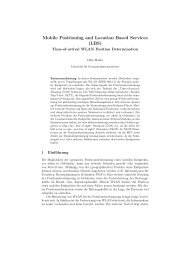
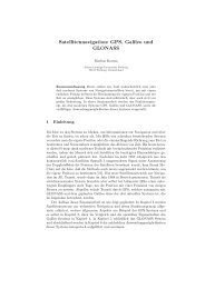
Figure 1: The overview of <strong>ADSL</strong>&<strong>PPPoE</strong>&<strong>RADIUS</strong><br />
In the Figure 1, we can see the overview of the <strong>ADSL</strong>. An example of <strong>ADSL</strong><br />
connection is better for the understanding of the three parts in my paper. On<br />
the PC, user clicks the browser or start the <strong>PPPoE</strong>-Client-Software, the data<br />
packages will be transmitted to <strong>ADSL</strong>-Modem via the Ethernet. There these<br />
packages will be parsed and transmitted to the “Splitter”. Then the data will go<br />
to DSLAM (Digital Subscriber Line Access Multiplexer (big Splitter)) via phone<br />
line. The voice signal will be transmitted to the telephone agency continuously<br />
and the data signal will be transmitted to B-RAS (Broadband-Remote Access<br />
Server) via ATM. B-RAS will send a package back via the same line. When the<br />
<strong>PPPoE</strong>-Client on the PC in home receives the package, it will send back a<br />
feedback package. After the B-RAS receives that feedback package from the<br />
user <strong>PPPoE</strong>-Client, it will send a package with accounting information to<br />
<strong>RADIUS</strong>-Server, where the account will be authorized and validated. Then the<br />
related data and status of “OK” will be sent back to the correct IP-Address in<br />
the same session. <strong>PPPoE</strong>-Client will start to configurate the PPP-Interface of<br />
the PC, and then the <strong>PPPoE</strong>-Client will set the current B-RAS IP-Address as<br />
the default route in the routing table and store it in the system. This means<br />
from now on all the data packages will be sent to B-RAS via the PPP-Interface<br />
(B-RAS will be treated as an Internet gateway) and continue the routing. At this<br />
point, the user is connected to the service provider (and the Internet).<br />
4
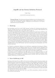
3,<strong>ADSL</strong><br />
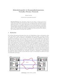
Figure 2: The <strong>ADSL</strong> in the OSI seven layer model<br />
The Open Systems Interconnection Reference Model (OSI Model or OSI<br />
Reference Model for short) is a layered abstract description for<br />
communications and computer network protocol in networking. It is also called<br />
the OSI seven layer model.<br />
The <strong>ADSL</strong>/DSL is in the first layer: physical layer in the OSI seven layer<br />
models. Because the physical layer concerns itself with the transmission of bits,<br />
I will introduce the physical aspects of the signal transmission in the next part.<br />
3,1 The principle of the signal transmission<br />
If the sender wants to send information, it will modulate the information to<br />
signals and transmit them to the receiver via the physical intermediate. The<br />
receiver will demodulate the signals to the original information, which can be<br />
used. The transform is done by a device called “modem”.<br />
3,2 The physical issues of signal transmission<br />
When signal is transmitting in the intermediate, it will be attenuated<br />
because of characteristic of the intermediate. After we know these issues, we<br />
can try our best to reduce attenuation of signals when doing the prophetic<br />
works.<br />
a) Attenuation of signal: With the continuous attenuation and weakening<br />
often signals in the transmitting process, it is possible that the signals<br />
cannot reach the receiver.<br />
b) Disturbance of signal: Because there might be some disturbance in the<br />
transmitting process, such as some other signals from other signal sources,<br />
5
what the receiver received would not be the original signals any more.<br />
3,3 Proposed modulation formats for <strong>ADSL</strong><br />
Modulation is a technique that converts the digital signal (binary 0 and 1)<br />
to analogy signal (such as the sine curve). The signal, that is modulated, is<br />
consist of a whole RF carrier. The modulation is the process of varying the<br />
amplitude, frequency, or phase of an RF carrier wave, the process whereby<br />
some characteristic of one wave is varied in accordance with some<br />
characteristic of another wave. The basic types of modulation are angle<br />
modulation, including the special cases of frequency modulation, amplitude<br />
modulation and phase modulation. The next part is the introduction of different<br />
modulation techniques, which are used in <strong>ADSL</strong>.<br />
3,3,1 The modulation technique<br />
3,3,1,1 Frequency modulation<br />
Frequency modulation is the simplest modulation. The definition of<br />
frequency is that the number of times an electromagnetic signal repeats an<br />
identical cycle (sine curve) in a unit of time, usually one second. The unit of<br />
frequency is Hz. One Hertz (Hz) is one cycle per second.<br />
There is a simple sample: if on a simple 300 band modem, 1070 Hz stands<br />
for binary value 0 and 1270 Hz stands for binary 1. Then we can transmit the<br />
binary values 0 and 1 by using these 2 frequencies. Of course, we can use<br />
more frequencies to transmit more signals. We can use A, B, C, D four<br />
frequencies to stand for 00, 01, 10, 11 four different signals. This makes the<br />
speed of transmit more quick. And we also transmit 3 bit information at same<br />
time when we use different 8 frequencies.<br />
3,3,1,2 Amplitude modulation<br />
After we know the principle of the frequency modulation, it is easier to<br />
understand the amplitude and phase modulation. In the amplitude modulation,<br />
we distinguish the different information via changing the amplitude,which is<br />
the height of the amplitude. The principle is same as the frequency modulation.<br />
3,3,1,3 Phase modulation<br />
To change the phase of cycle (sine curve) in a specific period, then we<br />
should send a new sine curve when stop to send the old sine curve in the<br />
sender. The new sine curve has the same frequency and the amplitude as the<br />
old sine curve. If we stop the old sine curve and start the new sine curve at the<br />
same, then there will not any difference between the new signal and the old<br />
6
one. But if we delay the sending of the new curve, that is to say: the phase of<br />
the sine curve will be changed. We can evaluate the unit of the change: degree.<br />
For the sin curve, 360 degree is a period. Using the different degree value in<br />
the different periods, we have more types to stand for more bits.<br />
3,3,2 Three different modulation of <strong>ADSL</strong><br />
If a technique of modulation only uses one carrier, then the modulation<br />
belong to single carrier modulation. Or it is multi carrier modulation.<br />
I will only introduce the three modulations related with <strong>ADSL</strong>, which are<br />
used frequently: QAM, CAP and DMT.<br />
3,3,2,1 QAM – Quadrature Amplitude modulation<br />
(single carrier modulation)<br />
QAM is the combination of the phase modulation and amplitude modulation<br />
techniques. First it distinguishes the different types on the phase of the base<br />
frequencies. Then it changes the amplitude. This technique can stands for<br />
4bits and can be used on the modems which speed could be 14.4K,28.8K and<br />
33.6K. Now it is no longer used on the 56K modem. But it is still used on the<br />
56K modem to transmit the signals from PC to phone line. See the diagram<br />
below. The diagram is a sample of 16QAM. It uses 12 different phases and<br />
four different amplitudes.<br />
Figure 3: Example of the QAM modulation<br />
3,3,2,2 CAP – Carrierless Amplitude phase<br />
(single carrier modulation)<br />
CAP is the first modulation technique which is used on the <strong>ADSL</strong> and is<br />
replaced with the DMT. CAP is also a technique that is combined the carrier<br />
7
amplitude with the phase modulation. The efficiency of the single carrier<br />
modulation is low because it is not only treated as the intermediate but also<br />
needs to transmit signals. The next will be the multi carrier modulation.<br />
3,3,2,3 DMT - Discrete multi tone (multi carrier modulation)<br />
Multi carriers modulation uses multiple carriers , which we call as<br />
“subcarriers” On each subcarrier, we can use different single carrier<br />
modulation.<br />
Figure 4: <strong>ADSL</strong> Frequency Spectra<br />
Now most of the <strong>ADSL</strong> and VDSL use DMT. The basic idea of DMT is to<br />
split the available bandwidth into a large number of subcarriers. DMT is able to<br />
allocate data so that the throughput of every single subcarrier is maximized. If<br />
some subcarrier can not carry any data, it can be turned off and the use of<br />
available bandwidth is optimised.<br />
First an equal number per tone is transmitted to measure the<br />
characteristics of the line. The processing of the signal takes place in ATU-R,<br />
and the optimised bit distribution information will be delivered for ATU-C by<br />
using the same phone-line at a secure low speed.<br />
<strong>ADSL</strong> DMT-systems the downstream carriers are divided into 256<br />
4-kHz-wide tones. The upstream channels are divided into 32 subcarriers.<br />
3,4 The xDSL<br />
<strong>ADSL</strong> is the most popular form of xDSL technology. xDSL (Digital<br />
subscriber line) is technology backed by telephone companies to provide next<br />
generation high bandwidth services to the home and business using the<br />
existing telephone cabling infrastructure. There are of xDSL, each designed for<br />
specific goals and the needs of the marketplace. By using the different<br />
8
modulation techniques,xDSL can be divided to several forms. The most<br />
frequently used are <strong>ADSL</strong>,HDSL,SDSL and VDSL.<br />
<strong>ADSL</strong>: Asymmetric DSL, with a larger portion of the capacity downstream,<br />
less upstream POTS (Plain Old Telephone Service). This is the current<br />
existing telecom device. The frequency values that can be used are from<br />
300Hz to 3.4 KHz. Then the <strong>ADSL</strong> technique has enough space to transmit<br />
signals. When signals are transmitting to home via the phone line, the splitter<br />
will depart the low frequency signals. The signals which frequencies are lower<br />
than 4 KHz are telephone signals. The splitter will transmit these signals to<br />
telephone device. Those signals that are in high frequencies will be passed to<br />
the modem. And the modem will modulate the signals until they become the<br />
binary values what can be used by computer.<br />
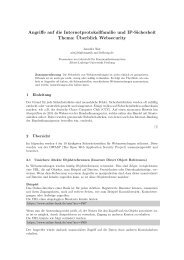
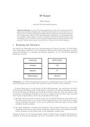
The diagram below is the work principle of <strong>ADSL</strong>. In the diagram, the<br />
upload speed is from 16 to 768kbps and the download speed is from 1.5 to<br />
9Mbps. Because most of the users receive their emails and read the news<br />
when they use Internet, the download speed is more than the upload speed.<br />
Because of the different upload speed and download speed, it is called<br />
Asymmetric DSL. The <strong>ADSL</strong> cable line must be shorter than 6km.<br />
Figure 5: Detailed <strong>ADSL</strong> Configuration<br />
The <strong>ADSL</strong> what uses the CAP modulation technique will use 25-160Khz as the<br />
upload channel and 240kHz-200kHz as download channel. The <strong>ADSL</strong> what<br />
uses the DMT modulation technique will use 25kHz – 200kHz as the upload<br />
channel and 240kHz – 1.1Mhz as the download channel.<br />
HDSL: High-bit-rate DSL, a technology for the business market. This<br />
technique uses two wire pairs. It was invented in 1980’s and developed for<br />
voice broadcasting first. And later it was used for the data transmitting. The<br />
length of the cable should be 3-4km. The limitation of the cable length is<br />
decided by the physical characteristics of the signal transmission. The HDSL is<br />
9
symmetric, that means the upload speed and download speed are same. If<br />
single wire is used, then the speed is 1.544mbit per second. If both of the wires<br />
are used, then the speed is 2mbit per second. Because of the same speeds<br />
and the dual wires it is more expensive than the <strong>ADSL</strong> and mostly used in<br />
companies. The HDSL uses the 300 -3.4Hz in the phone lien,so it doesn’t<br />
provide the POTS service like <strong>ADSL</strong>.<br />
SDSL: Symmetric DSL is a variation of HDSL using only one wire pair. The<br />
name has become more generic over time to refer to symmetric service at a<br />
variety of rates over a single loop.<br />
VDSL: Very high-bit-rate DSL which provides speeds up to 52 Mbps, but<br />
only for rather short distances, highest data rate of all。The intermediate of the<br />
technique are the wire which is consisted of fiber. The limitation of the cable is<br />
from 300m to 1.5km. The upload speed is 1.5-6.4Mbits per second and the<br />
download speed is 13-52Mbits per second。In fact is uses the frequencies<br />
above the voice frequency like <strong>ADSL</strong>. So it also uses POTS.<br />
The above different DSL are work in the physical layer of OSI, now coming the<br />
point of the network layer. In this layer, <strong>ADSL</strong> use PPP protocol to transmit the<br />
information packets.<br />
4,<strong>PPPoE</strong><br />
PPP, is a communications protocol for transmitting information over<br />
standard telephone lines. It is a member of the TCP/IP suite of network<br />
protocols. TCP/IP by itself cannot be transmitted over a serial link, so that we<br />
use the PPP transmit TCP/IP packets over a serial link. Since PPP was<br />
designed to do things that are not with Ethernet, there may be some confusion<br />
as to use PPP over Ethernet. PPP over Ethernet (<strong>PPPoE</strong>) is the solution that<br />
let the PPP (designed for serial communications) be adapted to an Ethernet<br />
network.<br />
4, 1 Introduction<br />
By combining the most economical LAN technique and the features of<br />
extensibility and the manageable control of the Ethernet Point to Point protocol,<br />
the network service providers and the telecom agencies can use the reliable<br />
and familiar techniques to speed up the deployment of high-speed internet<br />
service. It makes the service providers easier to support the multi-user<br />
wide-band connection services when they use the <strong>ADSL</strong>, cable modem or<br />
wireless connection. It also simplifies the configuration for the end users when<br />
they choose these services.<br />
10
<strong>PPPoE</strong>, defined in RFC 2516 (“A Method for Transmitting PPP over<br />
Ethernet (<strong>PPPoE</strong>)”) allows PPP transmission over Ethernet. This enables the<br />
provider both the advantages of the well-known Ethernet media and the<br />
advantages of a dial-up connection, in an “always-on” access network.<br />
<strong>PPPoE</strong> provides the ability to connect a network of hosts over a simple<br />
bridging access device to a remote Access Concentrator (AC). With this model,<br />
each host utilizes it's own PPP stack and the user is presented with a familiar<br />
user interface. <strong>PPPoE</strong> is easy to use - users accustomed to traditional dial-up<br />
will already be familiar with the <strong>PPPoE</strong> connection model.<br />
The below is the detail position of the <strong>PPPoE</strong> protocol in the data flow:<br />
Figure 6: Detailed position of the <strong>PPPoE</strong> protocol in the data flow<br />
4, 2 Two phases of <strong>PPPoE</strong><br />
There are phases to create a session based on the Point to Point protocol<br />
of the Ethernet: <strong>PPPoE</strong> discovery and <strong>PPPoE</strong> session. But when a user to<br />
creat the connection using the <strong>PPPoE</strong>, it is difficult to distinguish this phases.<br />
Because the <strong>PPPoE</strong> discovery phase is the phase that to creating the<br />
validation of the user connection of and connection contact phase. But the<br />
<strong>PPPoE</strong> session phase is a normal PPP phase after the connection is built.<br />
4,2,1 <strong>PPPoE</strong> Discovery<br />
In the phase, a user host will find a correct server, and then build the<br />
connection. The process can be four steps below:<br />
1. At the beginning, the user host broadcast the packages of <strong>PPPoE</strong> PADI<br />
(<strong>PPPoE</strong> Active Discovery Initiation) to find all the servers that can be<br />
connected possibly. Until it gets the PADO (<strong>PPPoE</strong> Active Discovery Offer)<br />
11
packages which were sent by one or more servers (most is one B-RAS).<br />
The user host’s Ethernet target address is the a broadcast address which<br />
is 0xfffffff and CODE field is 0x09,SESSION_ID is 0x0000. The PADI<br />
package should contain one tag of service name (The filed of the tag type<br />
is 0x0101) and the service which is asked for the server. A whole PADI<br />
(including the head of <strong>PPPoE</strong>) cannot exceed 1484 bytes to remain the<br />
enough for agent devices adding the tag of Relay-Session-Id.<br />
2. When the server receives the package of PADI in its service range it will<br />
send the PADO package to reponse the request. The PADO package<br />
must contain one tag (AC-Name) of connecting device type (The field of<br />
the AC-Name is 0x0102) and one or more tags of service names which<br />
indicates what the service types that can provide to the user hosts are. The<br />
CODE field is 0x07 and SESSION_ID still is 0x0000.<br />
3. The user host could choose one of connection devices after it received the<br />
PADO packages. The rule to choose is according the service name tags<br />
and the content in the tags. The user host chooses that one that the<br />
account is used in the server. Then the user host will send <strong>PPPoE</strong> PADR<br />
(<strong>PPPoE</strong> Discovery Request) package to the selected server to build a<br />
connection with the server. The CODE is 0x19 and SESSION_ID is still<br />
0x0000. The PADR package must include one service name tag to confirm<br />
the service type which requests to the connection devices. When the user<br />
host doesn’t receive PADO in specific time, it will send PADI again and<br />
wait double time at the same time. This process could be repeated several<br />
times if necessary.<br />
4. It starts the PPP session when the server received PADR package. After<br />
that it sends a <strong>PPPoE</strong> PADS package. The field of CODE is 0x65 and<br />
SESSION_ID is a unique session identity which is generated by the server.<br />
The ID is corresponded to the MAC of the server. 0xffff is the remain<br />
resource and cannot be used as SESSION_ID. PADS package must<br />
contains a service name tag to confirm the services provided to the user<br />
host. When the user host received the confirmation package both of them<br />
go into the session phase. If the server cannot recognize the service name<br />
tag which is in the PADR, it wills response a PADS package which<br />
contains service name error. The SESSION_ID is still 0x0000. If the user<br />
host doesn’t receive the PADS in a specific time, it will do the same as not<br />
receiving the PADS package.<br />
There is another package named <strong>PPPoE</strong> PADT. It can be sent at any time<br />
when the session is created by any part of the server or the user host to<br />
indicate the session is terminated. The PADT package doesn’t need any tags<br />
and the code field is 0xA7 and the SESSION_ID is the session id of the PPP<br />
12
session that needs to be terminated.<br />
If you open software such Ethereal or Packet Sniffer when using the <strong>ADSL</strong>,<br />
then these packets which are in the 4 steps of <strong>PPPoE</strong> Discovery can be got.<br />
What should be noticed of the configuration in the <strong>PPPoE</strong> Discover phase is<br />
the value of MTU (Maximum Transfer Unit). The maximum value of the<br />
Ethernet packet is 1500bytes. But the header of <strong>PPPoE</strong> needs 8 bytes. That is<br />
to say: when we setting the value of MTU, we have to minus the 8 bytes of the<br />
<strong>PPPoE</strong> header. So the maximum value of MTU should be 1492 bytes and not<br />
is 1500 bytes.<br />
4,2,2 <strong>PPPoE</strong> session<br />
Once each side knows the other's Ethernet address and the session<br />
number, the PPP session can begin. This PPP session is just like the normal<br />
PPP protocol.<br />
This phase is also the phase when <strong>ADSL</strong> user does his login operation at<br />
the ISP and prepares for later data transfer. In PPP phase, LCP (Link Control<br />
Protocol) will be adopted to authenticate by negotiating the appropriate<br />
protocol to proceed validation. LCP will also be adopted to handle some other<br />
properties of point-to-point connection.<br />
Figure 7: <strong>PPPoE</strong> Session Packets<br />
In order to establish such connection, both side of the communication will<br />
send a LCP packet to each other, which contains all possible options of<br />
connection. A LCP Acknowledge packet will be sent back in the case that both<br />
13
sides agree with these options. Otherwise, a LCP Nak (Not Acknowledge)<br />
packet will be sent back if some options are not accepted and the sender will<br />
keep waiting for the new Request packet. When the connection breaks finally,<br />
both sides should know the broken status. So we can see the importance of a<br />
sniffer program for the error control, because without a sniffer there is no other<br />
way to know why and where the connection is broken.<br />
There are two different ways to validate username and corresponding<br />
password over PPP connection:<br />
A) PAP Password Authentification Protocol<br />
B) CHAP Challenge Handshake Authentification Protocol<br />
PAP is simply sent the information of the username and password as the<br />
plaintext in packet without encryption. Obviously, it is dangerous. Anyone<br />
along the datalink can easily capture such critical information.<br />
So the second way, CHAP, is securer for such sensible information. By<br />
CHAP, sensible information such as password is not sent directly over the<br />
connection. In stead, Server sends to Client a “Challenge” including session ID<br />
and arbitrary challenge string; Client receives the “Challenge”, uses<br />
one-way-hash or MD5 algorithm to encrypt its sensible information and the<br />
received “Challenge” and sends the encrypted data back. Because Server<br />
knows all usernames and their corresponding passwords, it can encrypt the<br />
“challenge” and compares with the received the data. By this way, CHAP<br />
ensures the security over peer-peer connection.<br />
In <strong>ADSL</strong> technique, the authentication of the user login information is doing<br />
by the <strong>RADIUS</strong> server via the B-RAS.<br />
4,3,<strong>PPPoE</strong> Security Considerations<br />
To prevent attack of DOS (Denial of Service),Access Device should be<br />
able to generate a unique value according to the source address of PADR,<br />
which can ensure the reachability of PADI and limit the count of concurrent<br />
connections of this address. Although AC-Cookie is very useful and efficient, it<br />
cannot prevent all attacks of DOS. Some other techniques and methods can<br />
be used to against DOS on Access Device.<br />
4,4,The data flower<br />
The following sample explains the process of data transfer over PPP<br />
connection.<br />
Whenever a user wants to browse a normal webpage, he will input the right<br />
URL address in the web browser like FireFox and press return. The Web<br />
browser encapsulates all necessary information into a request packet<br />
according to HTTP protocol and sends it. These data will normally be<br />
14
transferred directly via TCP/IP stack and then physical layer. Now with PPPOE,<br />
system knows that the net is connected by AC and PPP-Interface. Instead of<br />
being sent to Ethernet Interface, these data will be sent to a virtual PPP<br />
Interface according to PPP protocol format. The purpose of <strong>PPPoE</strong> is to<br />
simulate a virtual PPP Interface, to encapsulate all received data with PPP<br />
packet format from the virtual Interface into Ethernet packet format, and then<br />
to send out all these encapsulated Ethernet data packet via the real Ethernet<br />
network device.<br />
Figure 8: Pseudo PPP TTY via <strong>PPPoE</strong><br />
4,5 The Experiment of the <strong>PPPoE</strong><br />
To see how the PPP protocol can work via Ethernet, and to analyze all the<br />
packets of <strong>PPPoE</strong>, I did the flowing experiment of the <strong>PPPoE</strong> in the university.<br />
Experimental environment: The university intranet PCs<br />
Operation system:SUSE 9.1<br />
Because the SUSE 9.1 has the PPPD, <strong>PPPoE</strong> and the <strong>PPPoE</strong> Server<br />
packages, so that I must not to install them again. If we use other Linux OS,<br />
maybe we should install such packages before.<br />
At first I chose a PC as the <strong>PPPoE</strong> server<br />
There are many options for the <strong>PPPoE</strong> Server, I selected the basic options.<br />
>pppoe-server -I etho -F -N 10 noauth<br />
And then I chose a PC to connect that <strong>PPPoE</strong> Server<br />
>pppd pty‘ppoe -I etho’ noauth<br />
15
At the same time I turn on the Ethereal, and I can catch all the packets of<br />
<strong>PPPoE</strong> under Ethereal.<br />
If there are many <strong>PPPoE</strong> Server in the intranet, we can use the useful option:<br />
Server name of the <strong>PPPoE</strong> Server<br />
>pppoe-server -I etho –N 10 – S servername noauth<br />
>pppd pty‘ppoe -I etho -S servername’ noauth<br />
For the authentication of the <strong>PPPoE</strong> connection, that is just like in normal<br />
PPP connection.<br />
Figure 9: <strong>PPPoE</strong> packets in Ethereal<br />
5 <strong>RADIUS</strong><br />
PPP can authenticate the user name and password, but many Tele companies<br />
have more than one AC (Access Concentrator) or B-RAS and they also<br />
provide several different services. So it is necessary to maintain a<br />
corresponding login record for each user to each ISP. The <strong>RADIUS</strong> is a<br />
solution for that. In stead of the PPP protocol work in the network layer of OSI<br />
model, the <strong>RADIUS</strong> protocol work in the application layer.<br />
5,1 Introduce<br />
16
<strong>RADIUS</strong> (Remote Authentication Dialin User Service Protocol) implements<br />
centralized authentication, authorization, and accounting for remote dial-up<br />
users in Client/Server mode. A <strong>RADIUS</strong> Client is typically a Network Access<br />
Server (NAS) and it passes user information to <strong>RADIUS</strong> Server. The <strong>RADIUS</strong><br />
Server authenticates and authorizes the request from <strong>RADIUS</strong> Client, and<br />
sends back the configuration information of the user. To ensure the security of<br />
data transmission, all data between Client and Server are encrypted by MD5.<br />
There are two different types of communication: Access Request and<br />
Accounting Request.<br />
<strong>RADIUS</strong> bases on UDP protocol and all <strong>RADIUS</strong> messages are sent and<br />
received as UDP packets. Authentication Service listens to port 1812 and<br />
Accounting Service listens to port 1813. <strong>RADIUS</strong> message consists of data<br />
fields as Code, ID, Length, Authenticator and Attributes.<br />
The login record data from user contains the username and password.<br />
Furthermore, some other user information such as surfing time and fee should<br />
also be stored in somewhere. That all of these different kinds of information<br />
should be kept in databases makes it a real challenge to manage. A good<br />
solution is to use central DBMS. So that <strong>RADIUS</strong> is the solution that widely<br />
used in <strong>ADSL</strong> systems. <strong>RADIUS</strong> has two different kinds of databases: one is<br />
for authentication with username and password information. The other is used<br />
to store some other information as time and fee. By this way, <strong>RADIUS</strong> system<br />
accesses the second database for user’s corresponding data after passing the<br />
authentication.<br />
Client is B-RAS. When establishing a PPP connection, the task of<br />
authentication is passed to <strong>RADIUS</strong> Server instead of previously local<br />
database. <strong>RADIUS</strong> Server will perform authentication by checking whether the<br />
given password matches the stored password or not. The B-RAS now takes<br />
over and carries the later actions according to the result of authentication<br />
5,1 Operations<br />
The type of packet is specified by the first byte of the packet.<br />
1) Access-Request<br />
This request is send by a <strong>RADIUS</strong> Client to Server when requesting<br />
authentication and authorization for a network access connection attempt. The<br />
request consists of username, password and NAS_Port and so on. Server will<br />
check for the corresponding record. When the given data match the stored<br />
data, Access-Accept response packet will be returned, otherwise<br />
Access-Reject.<br />
2) Access-Accept<br />
As mentioned, Server will return Client the Access-Accept response when<br />
the given data are all right, which means that the connection attempt is<br />
17
authenticated and authorized. Some configuration parameters are returned in<br />
the same response packet.<br />
3) Access-Reject<br />
Opposite to Access-Accept, Access-Reject is sent by Server to Client as<br />
the response to failed authentication and authorization, which means that the<br />
connection attempt is rejected.<br />
4) Accounting-Request<br />
This request is Send by the <strong>RADIUS</strong> Client to specify accounting<br />
information for an accepted connection. There are two kinds of situations. One<br />
is to inform Server to begin accounting when the connection passes<br />
authentication and authorization successfully. The other situation is to inform<br />
Server to stop accounting when the connection is broken. All of these<br />
information are stored for future usage.<br />
5) Accounting-Response<br />
This response is Send by the <strong>RADIUS</strong> server in response to the<br />
Accounting-Request message which informs the <strong>RADIUS</strong> Client the<br />
successful receipt and processing of the Accounting-Request message.<br />
5,3 <strong>RADIUS</strong> Security Considerations<br />
<strong>RADIUS</strong> actually doesn't send the password via internet. Instead, it<br />
generates a 128 bit random number (termed the "Request Authenticator"),<br />
appends the "shared secret" (the <strong>RADIUS</strong> password) to the number, and runs<br />
a one-way hash function or MD5 over it. It then takes this number and XORs<br />
the entered password against it, and sticks this in the "Password" attribute of<br />
an "Access-Request" packet.<br />
Because that <strong>RADIUS</strong> clients stick the random number into the packet, as<br />
the "Authenticator" field of the <strong>RADIUS</strong> packet, so that if an intruder already<br />
knows the password that the NAS is trying to clear with the <strong>RADIUS</strong> server,<br />
and the intruder can intercept the Access-Request packet sent by the NAS to<br />
the <strong>RADIUS</strong> server, the intruder has enough information to launch a dictionary<br />
attack against the <strong>RADIUS</strong> shared secret.<br />
The other kind of attack is that a remote user can flood a NAS with PPP<br />
requests that contain an invalid password, causing the NAS to turn around and<br />
send an Access-Request to the <strong>RADIUS</strong> server. While the flooding attack is in<br />
progress, it is reported that the <strong>RADIUS</strong> will lock up. When the attack stops,<br />
the server reportedly will resume normal operation.<br />
18
6 Reference<br />
R. Stevens, TCP/IP Illustrated Vol. 1<br />
[RFC-2516 ] PPP over Ethernet (<strong>PPPoE</strong>)<br />
[RFC-1661 ] The Point-to-Point-Protocol (PPP)<br />
[RFC-1334 ] Password Authenti_cation Protocol (PAP)<br />
[RFC-1994 ] Challenge Handshake Authenti_cation Protocol (CHAP)<br />
[RFC-2139 ] <strong>RADIUS</strong> Accounting<br />
[RFC-2865 ] Remote Authentication Dial In User Service (<strong>RADIUS</strong>)<br />
http://www.adslguide.org.uk/howitworks/authentication.asp<br />
http://homepage.interaccess.com/~jkristof/xdsl-faq.txt<br />
http://www.ks.uni-freiburg.de/download/inetworkSS04/pdf/inetwork04-11.pdf<br />
http://www.webopedia.com/TERM/R/<strong>RADIUS</strong>.html<br />
http://www.riverstonenet.com/solutions/802.1x.shtml<br />
19