Limitorque L120 Series - Flowserve Corporation
Limitorque L120 Series - Flowserve Corporation
Limitorque L120 Series - Flowserve Corporation

Create successful ePaper yourself
Turn your PDF publications into a flip-book with our unique Google optimized e-Paper software.
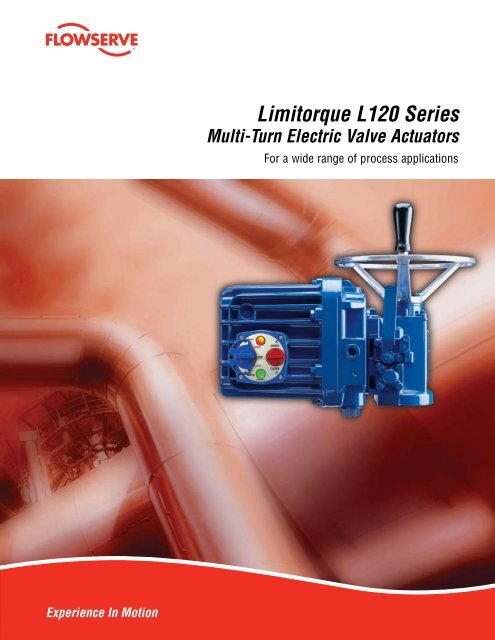
Experience In Motion<br />
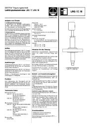
<strong>Limitorque</strong> <strong>L120</strong> <strong>Series</strong><br />
Multi-Turn Electric Valve Actuators<br />
For a wide range of process applications
2<br />
<strong>Flowserve</strong> <strong>Limitorque</strong> <strong>L120</strong> series multi-turn electric actuators<br />
have a solid record of making valve control easier in a wide<br />
variety of demanding applications.<br />
Proven performers under the most challenging circumstances,<br />
<strong>Limitorque</strong>’s <strong>L120</strong> actuators are ideal for valves<br />
requiring rotary or linear movement.<br />
With nine unit sizes, <strong>L120</strong> electric actuators make it easy to<br />
meet or exceed your requirements for positive, dependable<br />
valve actuation.<br />
Whether used with gate and globe valves, penstocks, or<br />
sluice gates, versatile <strong>L120</strong> <strong>Series</strong> actuators operate without<br />
modification in any rising or non-rising stem application for<br />
linear-action valves. When combined with a <strong>Limitorque</strong> PT,<br />
PTD, or HBC series quarter-turn gear operator, <strong>L120</strong> actuators<br />
can also be used to control butterfly, ball, and plug<br />
valves, as well as damper drives, flop gates, or any other<br />
device which requires rotary movement.<br />
Rugged, reliable, and versatile, <strong>L120</strong> actuators are proven<br />
performers in challenging applications. Thousands of<br />
<strong>L120</strong> actuators are at work in some of the world’s most<br />
demanding conditions, where nothing less than day-afterday<br />
dependable operation is acceptable.<br />
<strong>L120</strong> actuators are specified for use in petrochemical,<br />
power generation, and water and waste treatment applications<br />
where failure of a single actuator can be extremely<br />
costly…even catastrophic.<br />
Solid design and durable construction qualify the <strong>L120</strong><br />
actuator for applications involving harsh environmental<br />
conditions. A successful record with challenging requirements<br />
and compatibility with advanced process control<br />
systems make <strong>L120</strong> actuators the best combination of proven<br />
and leading-edge technologies. Backed by comprehensive<br />
technical support services, product documentation, and<br />
spare parts availability, the <strong>L120</strong> series is an easy choice for<br />
flexible, dependable valve control.
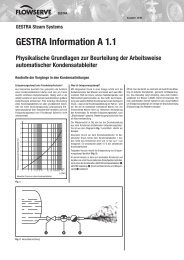
Low-maintenance<br />
requirements make the<br />
<strong>L120</strong> <strong>Series</strong> ideally suited<br />
for water and waste<br />
treatment applications.<br />
<strong>L120</strong> actuators meet<br />
rigid safety requirements<br />
and are available<br />
in weatherproof,<br />
explosionproof,<br />
and submersible<br />
configurations.<br />
The <strong>L120</strong> makes valve control easier for some<br />
of the world’s most demanding customers.<br />
Petrochemical installations such as refineries, pipelines,<br />
terminals, tank farms, cokers, and off-shore platforms rely<br />
on the <strong>L120</strong>’s safety, endurance, and operational efficiencies.<br />
The <strong>L120</strong> has network compatibility, explosionproof certification,<br />
and resistance to lightning, EMI, and fire.<br />
Power generation plants value the <strong>L120</strong>’s availability,<br />
controls versatility, and reliable performance. The <strong>L120</strong>’s<br />
rugged design and construction quality stands up to vibration,<br />
high-pressure steam, and extreme temperatures.<br />
Water and waste treatment facilities benefit from the<br />
<strong>L120</strong>’s low-maintenance requirements and modulating<br />
control capabilities. Actuators meet AWWA standards<br />
and easily fit the industry trend toward modern controls<br />
networks. The wide range of options in the <strong>L120</strong> <strong>Series</strong><br />
allows specification needs to be met cost-effectively.<br />
Designed to provide positive,<br />
dependable actuation.<br />
The time-tested design and solid construction of the <strong>L120</strong><br />
series allow these actuators to handle up to 60,000 ft-lb<br />
(81,600 N m) of torque, and up to 500,000 ft-lb (225,000 kg)<br />
of thrust. Durable torque overload protection is provided<br />
in both directions of valve travel. Rugged enclosures are<br />
available in weatherproof, submersible, and explosionproof<br />
configurations.<br />
<strong>L120</strong> actuators can also be coupled to gearboxes such<br />
as <strong>Limitorque</strong>’s B320, MT, PT, PTD, or HBC operators for<br />
motorized operation of valves requiring quarter-turn operation<br />
or multi-turn applications for increased torque and/or<br />
thrust requirements.<br />
All <strong>L120</strong> actuators are factory-lubricated and weatherproofed<br />
for service in temperature ranges from -50°C to<br />
65°C (-56°F to 150°F). Submersible, explosionproof, and<br />
extremely cold temperature versions of all <strong>L120</strong> models are<br />
available for appropriate applications. Refer to pages 8 and<br />
9 for <strong>L120</strong> specifications.<br />
flowserve.com
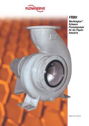
<strong>L120</strong> series multi-turn electric valve actuators<br />
<strong>L120</strong>-10 through - 0 series<br />
These models utilize die-cast aluminum with an option for<br />
ductile iron construction to withstand the most rigorous<br />
applications.<br />
All metallic gearing is lubricated.<br />
Anti-friction bearings are used<br />
throughout.<br />
Reliable motor includes class F<br />
insulation and thermal protection;<br />
it is specially designed for valve<br />
actuation.<br />
A four-position, 16-contact<br />
geared limit switch is standard<br />
on all models. The gear train is<br />
fully enclosed.<br />
Manual declutch lever mechanically<br />
disconnects the motor from the<br />
handwheel through the clutch assembly.<br />
Return to motor operation is automatic in<br />
all actuators when the motor is energized.<br />
Rugged, epoxy-based finish protects exterior surfaces.<br />
Enclosures are available in weatherproof, submersible<br />
and explosionproof construction. Gaskets and seals<br />
throughout prevent exposure to the elements.
<strong>L120</strong>-8 series<br />
This model and larger actuators feature cast iron construction.<br />
Optional ductile iron construction is also available.<br />
<strong>L120</strong> actuators offer easy control of all types of valves.<br />
Direct mounting The <strong>L120</strong> series can be directly coupled<br />
with valves for torque-only applications. For thrust<br />
applications, a separate thrust base is used for the <strong>L120</strong>-10<br />
through -85.<br />
<strong>L120</strong>/B320 AND <strong>L120</strong>/MT Rising stem valves may be<br />
operated by an <strong>L120</strong> coupled to a B320 or MT bevel gear<br />
operator. Thrusts up to 325,000 lb/147,420 N and torque up<br />
to 8,000 ft-lb/10,850 N m can be accommodated.<br />
<strong>L120</strong>/PT/PTD/HBC The <strong>L120</strong> series may be coupled to a<br />
worm gear reducer for operation of quarter-turn valves such<br />
as butterfly, balls, plugs, and dampers.<br />
Mounting bases<br />
Thrust actuator drive bases<br />
Type A1 (drive 2) – Alloy bronze (torque and thrust)<br />
Torque-only actuator bases<br />
Type B4 (drive 1) – Standard steel bushing<br />
Type BL (drive 3) – Splined steel bushing for rising or<br />
rotating stem valves<br />
Mounting bases (<strong>L120</strong>-10 through -85)<br />
Type B4<br />
(drive 1)<br />
Type A1<br />
(drive 2)<br />
Type BL (drive 3)<br />
<strong>L120</strong>-10 through -40<br />
<strong>L120</strong>-190 series<br />
This versatile midrange member of the <strong>L120</strong> family delivers<br />
more than seven times the thrust of the smallest actuators<br />
in the line.<br />
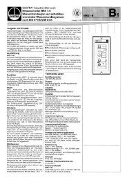
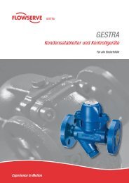
Valve mounting options<br />
<strong>L120</strong><br />
mounted to<br />
wedge gate<br />
<strong>L120</strong>/B320<br />
mounted to<br />
sluice gate<br />
<strong>L120</strong>/PT<br />
mounted to<br />
butterfly valve<br />
Combinations for torque reduction applications<br />
<strong>L120</strong>/B320 or MT Multi-turn <strong>L120</strong>/HBC, PT, or<br />
PTD Quarter-turn<br />
flowserve.com<br />
<strong>L120</strong>/PT<br />
mounted to<br />
damper
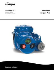
Compatible control options include switches, illuminated<br />
indicators, integral packages, and digital networks linked<br />
direct-to-host.<br />
Even though it has been at work for years, the <strong>L120</strong><br />
is at home in the most modern process control<br />
environments. It is compatible with a wide range of<br />
control options — from stand-alone actuators with<br />
local controls to open-standards-based, direct-to-host<br />
DDC networks with up to 250 actuators.<br />
Human interfaces<br />
Control stations are available with a variety of illuminated<br />
indicator and selector switch options. The control stations<br />
offer two lights and padlockable selector switches as<br />
standard for use with electronic controllers. Switch stations<br />
can be supplied in the compartment cover (standard) or for<br />
remote mounting.<br />
Control compartments<br />
Options for compartment sizes fit different control<br />
requirements. The smallest size is supplied to suit any<br />
application, unless another size is specified.<br />
• <strong>L120</strong>-10 through -190 Three sizes are available: standard<br />
– for NCU and BIC, plus some BIC configurations;<br />
minimum integral compartment – for clamshell, electronic<br />
integral controls, and <strong>L120</strong>-10 through -40 single-phase<br />
BIC; and maximum compartment – for some Modutronic<br />
controllers and customized options which do not fit smaller<br />
compartment sizes.<br />
• <strong>L120</strong>-420 and larger Two sizes apply: a standard<br />
compartment for non-integral controls and an integral<br />
compartment for integral controls.<br />
Control stations<br />
Typical control stations offer basic control functions.<br />
LOCAL<br />
REMOTE<br />
LOCAL<br />
REMOTE<br />
STOP<br />
STOP<br />
STOP<br />
STOP<br />
OFF<br />
LIMITORQUE<br />
OFF<br />
LIMITORQUE<br />
OPEN<br />
CLOSE<br />
Advanced control stations support electronic control<br />
functions.<br />
OPEN<br />
CLOSE<br />
<strong>L120</strong> control compartments<br />
Standard compartment<br />
• <strong>L120</strong>-10 through -190 for<br />
NCU and BIC controls<br />
• <strong>L120</strong>-420 and larger for<br />
non-integral controls<br />
Minimum integral<br />
compartment<br />
• <strong>L120</strong>-10 through -40 for<br />
single-phase BIC, and<br />
clamshell controls<br />
• <strong>L120</strong>-85 through -190 for<br />
clamshell controls<br />
Maximum integral<br />
compartment<br />
• <strong>L120</strong>-10 through -190<br />
for some modutronic<br />
packages and other<br />
customized options<br />
• <strong>L120</strong>-420 and larger for<br />
integral controls
Integral control packages expand <strong>L120</strong> functionality.<br />
Standard packages are provided on printed circuit boards to reduce the need for hard wiring.<br />
Local control stations offer a choice of indicator light and selector switch options. Control functions vary<br />
according to application requirements.<br />
Integral package options:<br />
• No Controls Unit (NCU) control of open/close applications<br />
can be linked to a motor control center or PLC to keep<br />
equipment costs to a minimum.<br />
• Basic Integral Controls (BIC) include integrated reversing<br />
contactor, transformer, fuses, and interlocks.<br />
• Integral Reversing Controls (IRC) include BIC functionality<br />
plus plug-in interconnect board and increased options. IRC<br />
packages are mounted on hinged clamshell bracket for easy<br />
accessibility.<br />
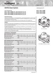
Advanced features simplify control characteristics<br />
No-controls unit<br />
Basic integral control (BIC)<br />
NCU<br />
BIC<br />
Electronic controller with distributed digital control<br />
DDC<br />
• Modutronic Controls (BIC/MOD 20) offer a choice of integral<br />
packages for positioning or process control functions in<br />
response to analog signals. Use with BIC and IRC packages.<br />
• Electronic controls offer state-of-the-art actuator control<br />
with advanced diagnostics and configurability. Available<br />
features include openclose, modulating, analog I/O, digital<br />
I/O, and networked protocols. Available protocols include<br />
DDC, PROFIBUS, and Foundation Fieldbus.<br />
<strong>L120</strong>/DDC direct-to-host networks support up to<br />
2 0 field units<br />
Host Controller<br />
1<br />
2<br />
250 ...<br />
3<br />
flowserve.com
8<br />
<strong>L120</strong> Specifications<br />
Gear housing<br />
• Cast aluminum, <strong>L120</strong>-10 through -40; cast iron, <strong>L120</strong>-85<br />
through -2000.<br />
• Lubrication — Grade 0 or Grade 00.<br />
• Gear reduction — Double reduction type.<br />
› Worm gear (alloy bronze) and spur gear (heat-treated steel),<br />
<strong>L120</strong>-10 through 85.<br />
› Worm gear (alloy bronze) and spur gear (heat-treated steel), and<br />
worm (alloy steel) and helical gearing (heat-treated steel), <strong>L120</strong>-<br />
190 through -2000.<br />
Electrical compartment covers<br />
• Cast aluminum, O-ring sealed.<br />
› Hardware is nickel-plated carbon steel, <strong>L120</strong>-10 through -85, and<br />
<strong>L120</strong>-190 through -2000. Stainless steel optional for non-XP.<br />
Motor<br />
• Available as four-pole, 1800 RPM (60Hz) or 1500 RPM<br />
(50Hz); two-pole, 3600 RPM (60Hz) or 3000 RPM (50Hz);<br />
eight-pole, 900 RPM (60Hz) or 750 RPM (50Hz).<br />
• Squirrel-cage induction for three-phase and capacitor startinduction<br />
run for single-phase.<br />
• Power supply — three-phase motors, suitable for 3/60/230,<br />
3/60/460, 3/60/575, 3/50/380, or 3/50/415.<br />
• Nominal duty is 15 minutes.<br />
• Dynamic torque is nominal 20% of start torque.<br />
• Class F insulation.<br />
• Two Class B thermal contacts embedded within motor<br />
windings provide thermal protection.<br />
Limit switch<br />
• Gear driven, cam operated, snap acting.<br />
• Four rotor/16 SPST contact switches (four contacts per rotor<br />
— 2 N/O and 2 N/C). Rotors may be set to open or close at<br />
any valve position.<br />
• Contact rating is 600 volts per ICS-125.6. Current rated 6<br />
amps resistive and 60 amps inrush at 120 VAC.<br />
• Max drive sleeve turns (four-gear) rated 630 for <strong>L120</strong>-10;<br />
740 for <strong>L120</strong>-20; 640 for <strong>L120</strong>-40; 900 for <strong>L120</strong>-85; 3110<br />
for <strong>L120</strong>-190; 3300 for <strong>L120</strong>-420; 2850 for <strong>L120</strong>-800; 1210<br />
for <strong>L120</strong>-2000.<br />
Torque switch<br />
• <strong>L120</strong>-10 through -85: Heavy-duty inlaid silver contacts,<br />
600 volts, and one SPST contact each for open/closed<br />
direction dedicated to actuator torque protection.<br />
• <strong>L120</strong>-190 through -2000: 600 volts per ICS-125.6, 6 amps<br />
resistive and 60 amps inrush at 120 VAC. One SPST contact<br />
each for open/closed direction dedicated to actuator torque<br />
protection.<br />
Reversing contactor<br />
• Available at 12-, 25- or 50-amp ratings, selected according<br />
to motor ratings.<br />
Enclosure<br />
• WP actuators suitable for NEMA 4.<br />
• XP actuators suitable for<br />
› FM Class I, Groups B, C, D, Divisions 1 and 2;<br />
Class II, Groups E, F, G, Divisions 1 and 2.<br />
› CSA Class I, Groups C, D, Divisions 1 and 2;<br />
Class II, Groups E, F, G, Divisions 1 and 2<br />
NOTE: XP actuators also carry NEMA 3 and 4 ratings.<br />
Output drive B4<br />
• Steel torque bushing, no internal machining. Torque bushing<br />
is flush with mounting base, not extended.<br />
Handwheel/declutch<br />
• Fabricated steel, or ductile iron for side-mounted; cast<br />
aluminum for <strong>L120</strong>-10 top-mounted only. Handwheels are<br />
connected directly to drive sleeve (<strong>L120</strong>-10, -20 and -40).<br />
<strong>L120</strong>-85 operates through the worm set. Declutch lever is<br />
padlockable in motor position.<br />
Mounting base<br />
• Supplied to MSS (English taps) standard. Optional ISO bases<br />
available.<br />
Paint<br />
• Valspar epoxy/polyurethane and E-coating (electrodeposition)<br />
for <strong>L120</strong>-10 through -40; Valspar epoxy/<br />
polyurethane for <strong>L120</strong>-85 through -2000. Both coatings are<br />
suitable for 500-hour salt spray.<br />
Temperature rating<br />
• Standard operating temperature range is from -20°F to<br />
150°F. Optional extended ranges available.<br />
• FM explosionproof rating -20°F to 140°F (-20°C to 60°C)<br />
Unit nameplate<br />
Actuator nameplate<br />
• <strong>Flowserve</strong> <strong>Limitorque</strong> name, point of manufacture, actuator<br />
type and size, order number, serial number, space for<br />
customer tag information. Nameplate located on back of<br />
actuator opposite the limit switch compartment.<br />
Motor nameplate<br />
• ID number, start torque, run torque, enclosure type, RPM,<br />
volts, full load amps, locked rotor amps, insulation class,<br />
duty, space heater size, horsepower, service factor, phase,<br />
cycles, motor code, ambient temperature, connection<br />
diagram.
XP nameplate<br />
• <strong>L120</strong>-10 through -85:<br />
› Nameplated as Class I, Groups B, C, D, Divisions 1 and 2; Class II,<br />
Groups E, F, G, Divisions 1 and 2 with FM label. Class I, Groups<br />
C, D, Divisions 1 and 2; Class II, Groups E, F, G, Divisions 1 and 2<br />
with CSA label.<br />
› FM and CSA labels available for NCU and standard controls<br />
packages.<br />
• <strong>L120</strong>-190 through -2000:<br />
› Nameplated as Class 1, Groups C and D, Divisions 1 and 2, and<br />
Class II, Groups E, F and G, Divisions 1 and 2, FM or CSA label.<br />
Options<br />
• Flip-flop indication Local position indicator shows<br />
open-intermediate-closed positions and is driven by gear<br />
limit switch rotors. Window in compartment cover shows<br />
indicator.<br />
• Local continuous position indication Local position indicator<br />
shows continuous valve position in percentage open via dial,<br />
and is driven by dedicated gear set selected per application.<br />
Window in compartment cover shows indicator.<br />
• Local/remote indication Includes local continuous position<br />
indicator with a 1000-ohm potentiometer. Potentiometers<br />
transmit valve position to remote location.<br />
• R/I converter Sends remote valve position indication signal<br />
via 4-20 mA signal. Internally-powered.<br />
• Relay boards Provide isolated relays (2) or non-isolated<br />
relays (3) for interlocking with field equipment. Relay<br />
contacts rated at 250 VAC/6.5 A or 30 VDC/5 A.<br />
• Side-mounted handwheel (<strong>L120</strong>-10 through -40) Bevel<br />
gear attachment may be added to reduce effort required to<br />
operate handwheel, requiring more turns.<br />
• Handwheel spur (<strong>L120</strong>-190 through -2000) May be added<br />
to reduce effort required to operate handwheel, requiring<br />
more turns.<br />
• Five-gear limit switch Used when the number of drive<br />
sleeve turns exceeds capacity of four-gear limit switch.<br />
Provides 10 times the number of turns as four-gear switch.<br />
• Double-pole torque switch Provides an additional SPDT<br />
contact in each direction that actuates when set torque is<br />
exceeded. Used as indication of over-torque condition.<br />
• Ductile iron housing (<strong>L120</strong>-10 through -40) Ductile iron for<br />
load-carrying components.<br />
• Spring compensation (<strong>L120</strong>S) (<strong>L120</strong>-190 through -2000)<br />
SB-type spring-compensated stem nut used on high-speed,<br />
or high-temperature, torque-seated applications.<br />
• Position feedback for DDC Communicates valve position to<br />
remote location via DDC network. Includes local position<br />
indication, 1000-ohm potentiometer, and DDC analog<br />
channel. Used with DDC base actuator.<br />
• External analog feedback for DDC Allows external analog<br />
signals to be connected to DDC field unit, converted to<br />
digital signals, and transmitted over DDC network. Four<br />
signals may be accommodated. Includes DDC analog<br />
channel. Used with DDC base actuator.<br />
• Positioning control for DDC Permits positioning of valves<br />
over DDC network. Positioning commands valve to any<br />
point of travel, in 1% increments. Includes local position<br />
indication, 1000-ohm potentiometer, and DDC analog<br />
channel. Used with DDC base actuator.<br />
• Two-speed operation for DDC Allows the actuator to be<br />
pulsed on and off, achieving slower operating speed for all<br />
or part of valve stroke. Default pulse rate is 2 seconds on,<br />
10 seconds off, adjustable from 50 ms to 12.75 seconds<br />
in 50-ms increments. Configured via RS-232 link and<br />
dedicated software.<br />
Testing summary<br />
Weatherproof enclosures meet NEMA 4, NEMA 4X, and IP67.<br />
Submersible actuators are suitable for NEMA 6 and IP68.<br />
Explosionproof enclosures fully conform to and are certified<br />
to be compliant to the following:<br />
• Factory Mutual (FM) — Class I, Divisions 1 and 2, Groups<br />
B, C and D and Class II, Divisions 1 and 2, Groups E, F, G;<br />
Temp Code T3C.<br />
• Canadian Standards Association (CSA) — Class I, Division 1,<br />
Groups C and D and Class II, Division 1, Groups E, F and G;<br />
Temp Code T3C<br />
<strong>Limitorque</strong>’s factories are certified to ISO 9001 standards<br />
and maintain the highest quality of performance throughout<br />
the manufacturing processes.<br />
<strong>L120</strong> actuators meet the following seismic and vibration<br />
criteria: NTS Labs, Acton, MA, Test Report #31437-94M<br />
dated 3/28/94 to the following:<br />
• Sine survey; 5 to 200 Hz @ 0.75 g.<br />
• Sine cycling; 5 to 200 Hz to 5 Hz @ 0.75 g.<br />
• Sine cycling; 2 to 35 to 2 Hz @ 1.0 g; 10 cycles.<br />
• Sine dwells; 2 to 35 to 2 Hz @ 1/3-octave intervals,<br />
5.0 g @ 15-second dwells each frequency.<br />
NOTE: Standards are applicable to most actuators.<br />
flowserve.com<br />
9
10<br />
<strong>L120</strong> <strong>Series</strong> Performance<br />
(3-phase-50 Hz/380, 400, and 415 V — 60 Hz/230, 460, and 575 V)<br />
Actuator Maximum Torque Capacity Maximum Thrust Capacity Output Speed Range (RPM)<br />
ft-lb N m lb kg 60 Hz 50 Hz<br />
<strong>L120</strong>-10 100 136 10000 4500 12-250 10-210<br />
<strong>L120</strong>-20 200 272 20000 9000 12-250 10-210<br />
<strong>L120</strong>-40 400 544 30000 13500 24-250 20-210<br />
<strong>L120</strong>-85 850 1156 45000 20250 24-192 20-160<br />
<strong>L120</strong>-190 1900 2584 75000 33750 24-196 20-160<br />
<strong>L120</strong>-420 4200 5712 140000 63000 19-196 16-165<br />
<strong>L120</strong>-800 8000 10880 250000 112500 12-168 10-140<br />
<strong>L120</strong>-2000 20000 27200 500000 225000 12-60 10-50<br />
Maximum stem acceptance<br />
Actuator Threaded Stem Nut Bore Keyway Handwheel Gear Ratio<br />
in. mm in. mm in. mm STD Optional<br />
<strong>L120</strong>-10 1.25 32 1 25 1/4 x 3 ⁄32 8 x 6 1:1 4.2:1<br />
<strong>L120</strong>-20 2.25 57 1.875 47 1/2 x 3 ⁄8 14 x 9 1:1 5.7:1<br />
<strong>L120</strong>-40 2.625 66 2.125 52 1/2 x 3 ⁄8 16 x 10 1:1 12:01<br />
<strong>L120</strong>-85 3.25 76 2.75 70 5 ⁄8 x 7 ⁄16 20 x 12 18:1–71:1 (see Note 1)<br />
<strong>L120</strong>-190 3.5 89 2.875 73 3/4 x 1/4 20 x 12 22:1 88:1<br />
<strong>L120</strong>-420 5 127 4.25 108 1 x 3/4 28 x 16 28:1 170:1<br />
<strong>L120</strong>-800 5 127 7 178 1 x 3/4 32 x 18 N/A 24:168<br />
<strong>L120</strong>-2000 6.25 159 8 203 1-1/4 x 7 ⁄8 40 x 22 270:1 772:1<br />
<strong>L120</strong> weights (approx.)<br />
Actuator<br />
Actuator with STD<br />
Comp.<br />
Add for Integral<br />
Comp.<br />
Add for Max. Comp. Add for Thrust Base<br />
Add for Side-Mount<br />
Handwheel<br />
lb kg lb kg lb kg lb kg lb kg<br />
<strong>L120</strong>-10 90 41 20 9 32 14 7 3 3 1<br />
<strong>L120</strong>-20 115 52 20 9 32 14 13 6 8 4<br />
<strong>L120</strong>-40 160 72 20 9 32 14 22 10 16 7<br />
<strong>L120</strong>-85 285 129 20 9 32 14 67 30 (Note 2)<br />
<strong>L120</strong>-190 600 272 85 39 (Note 2) (Note 2) (Note 2)<br />
<strong>L120</strong>-420 1195 541 215 98 (Note 2) (Note 2) (Note 2)<br />
<strong>L120</strong>-800 1415 641 215 98 (Note 2) 430 195 (Note 2)<br />
<strong>L120</strong>-2000 2550 1155 215 98 (Note 2) 826 375 (Note 2)<br />
Note 1: Same as overall ratio.<br />
Note 2: Consult factory for weight.<br />
Note 3: Performance ratings and dimensions are also available for the <strong>L120</strong>-6000. Please consult factory.<br />
Mounting Base and Drive Sleeves<br />
Previous Designation Description<br />
Type B4 Drive 1 Bore and key bushing for torque-only applications<br />
Type A1 Drive 2 Threaded for thrust applications<br />
Type BL Drive 3 Splined steel bushing for rising rotating stem valves
<strong>L120</strong>-10, -20 and -40<br />
Drive sleeve <strong>L120</strong>-10 <strong>L120</strong>-20 <strong>L120</strong>-40<br />
in. mm in. mm in. mm<br />
Type B4 bore 1.00 24.5 1.88 47.8 2.13 54.1<br />
Type B4 key 1/4 x 3 ⁄32 1/2 x 3 ⁄16 1/2 x 3 ⁄16<br />
Type B4 stem nut 2.87 73 3.12 79 3.37 86<br />
Type A1 threaded stem 1.25 32.8 2.25 57.2 2.63 66.8<br />
Type A1 stem length 2.83 60 3.25 83 3.86 98<br />
Type BL splined 6 and 38 splines 6 and 38 splines 6 splines<br />
Type BL spline length 4.5 114 4.5 114 4.5 114<br />
Mounting base MSS ISO MSS ISO MSS ISO<br />
Pilot diameter 2.312 70 3.750 100 3.750 100<br />
Mounting holes (Note 1) (4) 3 ⁄8-16x.88 (4)M10x1.5x22.4 (4) 5 ⁄8-11x1.25 (4)M16x2x32 (4) 5 ⁄8-11x1.25 (4)M16x2x32<br />
Between centers 4.016 102 5.5 140 5.5 140<br />
Mounting base diameter 4.92 125 7.00 178 7.00 178<br />
<strong>L120</strong>-85, -190 and -420<br />
Drive sleeve <strong>L120</strong>-85 <strong>L120</strong>-190 <strong>L120</strong>-420<br />
in. mm in. mm in. mm<br />
Type B4 bore 2.75 69.9 2.88 73.2 4.25 108<br />
Type B4 key 5 ⁄8 x 7 ⁄32 3/4 x 1/4 1 x 3 ⁄8<br />
Type A1 threaded stem 3.0 76 3.5 89 5 127<br />
Type A1 stem length 7 177.8 8.25 209.6 9.38 238.3<br />
Mounting base MSS ISO MSS ISO MSS ISO<br />
Pilot diameter 5 130 7 230 8.5 215.9<br />
Mounting holes (Note 1) (4)3/4-10x1.0 (4)M20x2.5x26(s) (8)3/4-10x1.13(s) (8)M20x2.5x32 (8)7/8-9x1.75 (8)M30x3.5x1.75<br />
Between centers 6.5 165.1 11.75 298 14 355.6<br />
Mounting base diameter 8.25 209.6 13.5 343 16 406.4<br />
Note 1: Mounting holes straddle centerline.<br />
Note 2: <strong>L120</strong>-85, -190 and -420 are suitable for both torque and thrust applications. <strong>L120</strong>-optional. <strong>L120</strong>-2000 is suitable for torque as<br />
standard; thrust units are optional.<br />
<strong>L120</strong>-800 and -2000<br />
Drive sleeve <strong>L120</strong>-800 <strong>L120</strong>-2000<br />
in. mm in. mm<br />
Type B4 bore 4.5 108 6.25 159<br />
Type B4 key 1 x 1/2 N/A 1.24 x .438 N/A<br />
Type B4 stem nut 11 279.4 12 304.8<br />
Type A1 threaded stem 5 127 6.25 159<br />
Type A1 stem length 2 50.8 3.125 79.4<br />
Type A1 base to drive sl. 15.5 393.7 18.6 472.4<br />
Mounting base MSS ISO MSS ISO<br />
Pilot diameter 9 300 13 330<br />
Mounting holes (Note 1) (8)1.25-7x2.00 (8)M36x4x64 (12)15-6x3 N/A<br />
Between centers 16 406 18 457.2<br />
Mounting base diameter 18.8 477.5 21 533.4<br />
Note 1: Mounting holes straddle centerline.<br />
Note 2: <strong>L120</strong>-85, -190, -420, and -800 are suitable for both torque and thrust applications. <strong>L120</strong>-2000 is suitable for torque as standard;<br />
thrust base is optional.<br />
flowserve.com<br />
11
12<br />
Standard Compartment, <strong>L120</strong>-10 Through - 0<br />
Top view<br />
C<br />
C<br />
Front view<br />
8.3 max<br />
211<br />
8.3 max<br />
G 211<br />
8.3 max G<br />
211<br />
drive sleeve<br />
drive sleeve drive sleeve<br />
motor<br />
motor motor<br />
C<br />
2.5 I max<br />
64<br />
2.5 I max<br />
64 2.5<br />
64<br />
I max<br />
G<br />
3<br />
3<br />
3<br />
A 1<br />
A 1<br />
A 1<br />
motor<br />
motor<br />
motor<br />
Dimensions in inches<br />
A B C D E F G H I J<br />
<strong>L120</strong>-10 12 12.1 1.6 4.7 1.10 8.5 4.0 15.4 14.2 1.25<br />
<strong>L120</strong>-20 18 13.6 2.6 5.7 0.51 10.6 4.4 16.4 16.0 2.5<br />
<strong>L120</strong>-40 24 16.1 2.5 6.2 1.21 12.0 5.2 17.0 18.9 3<br />
Dimensions in millimeters<br />
A B C D E F G H I J<br />
<strong>L120</strong>-10 305 307 41 119 28 216 102 391 361 32<br />
<strong>L120</strong>-20 457 345 66 145 13 269 112 417 406 64<br />
<strong>L120</strong>-40 607 409 64 158 30 305 132 432 480 76<br />
Item 1: A dimension is the standard diameter handwheel.<br />
Item 2: 1-1/2 NPT (2) places farside.<br />
Item 3: J NPT (type A1 (drive 2) only).<br />
Item 4: Position indicator.<br />
1.5 3.2<br />
1.5 38<br />
3.2 81<br />
38<br />
1.5<br />
81<br />
5.9 38<br />
5.9<br />
150<br />
150<br />
3.2<br />
81<br />
5.9<br />
150<br />
drive sleeve<br />
drive sleeve<br />
Item 5: Mounting base location for types B4 (drive 1) and BL<br />
(drive 3).<br />
6<br />
2<br />
2<br />
drive sleeve<br />
6<br />
5<br />
5<br />
6<br />
D<br />
D<br />
4<br />
4<br />
2<br />
4.0<br />
102<br />
4.0<br />
102<br />
5<br />
D<br />
B max<br />
B max<br />
E<br />
Side view<br />
9.1<br />
9.1 231<br />
231<br />
10.5<br />
10.5<br />
267<br />
4.6 267<br />
4.6<br />
117<br />
117<br />
4<br />
E<br />
4.0<br />
102<br />
B max<br />
E<br />
H<br />
H<br />
9.1<br />
231<br />
10.5<br />
267<br />
4.6<br />
117<br />
H<br />
D<br />
D<br />
1" NPT<br />
1" NPT<br />
drive sleeve<br />
drive sleeve<br />
D<br />
1" NPT<br />
Item 6: Mounting base location for type A1 (drive 2).<br />
Item 8: Declutch lever is padlockable in motor operation.<br />
Item 9: Reference location of J NPT for stem cover.<br />
Item 10: Maximum rising stem without stem cover.<br />
NOTE: Actuator turns clockwise to close (left-hand thread).<br />
If other rotation is required, it must be specifically<br />
requested.<br />
8<br />
8<br />
10<br />
drive sleeve<br />
10<br />
J 9 8<br />
J 9<br />
F<br />
F<br />
10<br />
J 9<br />
F
8.3 max<br />
211<br />
Minimum Integral Compartment, <strong>L120</strong>-10 Through - 0<br />
G<br />
Top view<br />
Front view<br />
2.5<br />
64<br />
K<br />
8.3 max<br />
211<br />
C<br />
I max<br />
G<br />
3<br />
drive sleeve<br />
drive sleeve<br />
motor<br />
motor<br />
K<br />
C<br />
A 1<br />
2.5 I max<br />
64<br />
8.3 max<br />
211<br />
A 1<br />
11.0<br />
279<br />
G<br />
Dimensions in inches<br />
A B C 6 D E F G H I J K<br />
<strong>L120</strong>-10 12 12.1 1.6 4.7 1.10 8.5 4.0 15.4 14.2 1.25 6.6<br />
<strong>L120</strong>-20 18 13.6 2.6 5.7 0.51 10.6 4.4 16.4 16.0 2.5 7.6<br />
<strong>L120</strong>-40 24 16.1 2.5 6.2 1.21 12.0 5.2 17.0 18.9 3 8.1<br />
Dimensions in millimeters<br />
A B C D E F G H I J K<br />
<strong>L120</strong>-10 305 307 41 119 28 216 102 391 361 32 168<br />
<strong>L120</strong>-20 457 345 66 145 13 269 112 417 406 64 193<br />
<strong>L120</strong>-40 607 409 64 158 30 305 132 432 480 76 206<br />
Item 1: A dimension is the standard diameter handwheel.<br />
Item 2: 1-1/2 NPT (2) places farside.<br />
Item 3: J NPT (type A1 (drive 2) only).<br />
3<br />
K<br />
2.5<br />
64<br />
Item 4: Position indicator.<br />
C<br />
3<br />
3.2<br />
3.2 1.5<br />
A 1<br />
81<br />
1.5 38<br />
81 5.9<br />
38 5.9<br />
150<br />
11.0<br />
7.0<br />
279 150 11.0<br />
178<br />
7.0 279<br />
178<br />
I max<br />
drive sleeve<br />
motor<br />
drive sleeve<br />
Item 5: Mounting base location for types B4 (drive 1) and BL<br />
(drive 3).<br />
Item 6: Mounting base location for type A1 (drive 2).<br />
2<br />
drive sleeve<br />
6<br />
5<br />
2<br />
D<br />
D<br />
19.0 (483)<br />
19.0 right 3.2<br />
(483) swing<br />
1.5<br />
right clearance<br />
38<br />
swing<br />
81<br />
38 5.9<br />
clearance<br />
150<br />
7.0<br />
178<br />
5<br />
4<br />
4.0<br />
102<br />
drive sleeve<br />
B B max max<br />
4.0<br />
102<br />
4<br />
B max<br />
6<br />
7<br />
2<br />
10.5 10.5<br />
267 4.6 267<br />
117<br />
5<br />
D<br />
19.0 (483)<br />
right swing<br />
clearance<br />
4.6<br />
117<br />
Side view<br />
H<br />
H<br />
D<br />
D<br />
drive sleeve<br />
drive sleeve D<br />
E<br />
E<br />
1" NPT<br />
1" NPT<br />
E 1" NPT<br />
4<br />
4.0<br />
102<br />
B max<br />
7<br />
10.5<br />
4.6 267<br />
117<br />
H<br />
Item 7: Selector switch control elements. See wiring diagram<br />
for quantity and function.<br />
Item 8: Declutch lever is padlockable in motor operation.<br />
Item 9: Reference location of J NPT for stem cover.<br />
Item 10: Maximum rising stem without stem cover.<br />
NOTE: Actuator turns clockwise to close (left-hand thread).<br />
If other rotation is required, it must be specifically<br />
requested.<br />
10<br />
8<br />
J 9<br />
10<br />
drive sleeve<br />
8<br />
F<br />
J 9<br />
F<br />
10<br />
8<br />
flowserve.com<br />
J 9<br />
F<br />
1
1<br />
Maximum Integral Compartment, <strong>L120</strong>-10 Through - 0<br />
Top view<br />
8.3 max<br />
211<br />
K 8.3 max<br />
211 C<br />
C<br />
8.3 max<br />
211<br />
Front view<br />
G<br />
G<br />
K<br />
2.5<br />
64 2.5 drive sleeve 2.5<br />
64 drive 64 sleeve drive sleeve<br />
motor<br />
motor motor<br />
K<br />
C<br />
I max<br />
I max<br />
16.6<br />
422 16.6<br />
422<br />
1.5 3.2<br />
38 1.5 81 3.2<br />
38<br />
5.9<br />
81 1.5<br />
I max 150 5.9 38<br />
150<br />
16.6<br />
7.0<br />
178 7.0<br />
422<br />
178<br />
24.8 (629) right<br />
swing 24.8 clearance (629) right<br />
swing clearance 24.8 (629) right<br />
3.2<br />
swing E clearance<br />
81<br />
E<br />
5.9<br />
150<br />
7.0<br />
178<br />
motor<br />
motor<br />
G<br />
motor<br />
Dimensions in inches<br />
A B C D E F G H I J K<br />
<strong>L120</strong>-10 12 12.1 1.6 4.7 0.0 8.5 4.0 16.8 14.2 1.25 5.8<br />
<strong>L120</strong>-20 18 13.6 2.6 5.7 0.35 10.6 4.4 17.8 16.0 2.5 6.8<br />
<strong>L120</strong>-40 24 14.0 2.5 6.2 1.01 12.0 5.2 18.4 18.9 3 7.4<br />
Dimensions in millimeters<br />
A B C D E F G H I J K<br />
<strong>L120</strong>-10 305 307 41 119 0 216 102 427 361 32 147<br />
<strong>L120</strong>-20 457 345 66 145 9 269 112 452 406 64 173<br />
<strong>L120</strong>-40 610 356 64 158 26 305 132 467 480 76 188<br />
Item 1: A dimension is the standard diameter handwheel.<br />
Item 2: 1-1/2 NPT (2) places farside.<br />
Item 3: J NPT (type A1 (drive 2) only).<br />
Item 4: Position indicator.<br />
drive sleeve<br />
drive sleeve<br />
Item 5: Mounting base location for types B4 (drive 1) and BL<br />
(drive 3).<br />
Item 6: Mounting base location for type A1 (drive 2).<br />
6<br />
6<br />
5<br />
3<br />
2<br />
D<br />
3<br />
2<br />
drive sleeve<br />
D<br />
4<br />
5 4<br />
4.0<br />
102<br />
4.0<br />
102<br />
6<br />
B max<br />
B max<br />
5<br />
3<br />
2<br />
D<br />
7<br />
7<br />
H<br />
10.9<br />
277<br />
10.9<br />
4.8<br />
277<br />
122<br />
4.8<br />
122<br />
4<br />
4.0<br />
102<br />
B max<br />
Side view<br />
H<br />
A 1<br />
A 1<br />
7<br />
10.9<br />
277<br />
4.8<br />
122<br />
E<br />
H<br />
D<br />
D<br />
1" NPT<br />
1" NPT<br />
A 1<br />
drive sleeve<br />
drive sleeve<br />
D<br />
8<br />
10<br />
10<br />
1" NPT<br />
8<br />
J 9<br />
J 9<br />
drive sleeve<br />
Item 7: Selector switch control elements. See wiring diagram<br />
for quantity and function.<br />
Item 8: Declutch lever is padlockable in motor operation.<br />
Item 9: Reference location of J NPT for stem cover.<br />
Item 10: Maximum rising stem without stem cover.<br />
NOTE: Actuator turns clockwise to close (left-hand thread).<br />
If other rotation is required, it must be specifically<br />
requested.<br />
F<br />
F<br />
8<br />
10<br />
J 9<br />
F
S<br />
Q<br />
M<br />
R ma x<br />
19.0 (483) right swing clearance<br />
T<br />
N<br />
19.0 (483) right swing clearance<br />
T<br />
N<br />
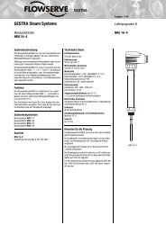
Minimum Integral Compartment, <strong>L120</strong>-8 (Shown) and -190,<br />
MSS 4. 0 P (Note ma x ) and ISO B ma x bases 4.0 (Note )<br />
S<br />
Top view<br />
R ma ma x x<br />
D<br />
S<br />
D<br />
Front view<br />
Q<br />
M<br />
Q<br />
M<br />
102<br />
2<br />
drive sleeve<br />
4. 0 P ma C x<br />
102<br />
motor<br />
2 C 5 motor<br />
C motor<br />
drive sleeve<br />
C<br />
C<br />
motor<br />
C motor<br />
Dimensions in inches<br />
A B C D E F G H I J K L M N O P Q R S T U<br />
<strong>L120</strong>-85 12 10.1 2.7 2.7 2.8 3.8 6.5 10.5 1.4 9.8 8.1 5.9 5.9 7.0 17.4 25.7 12.1 10.5 8.6 11.0 4<br />
<strong>L120</strong>-190 18 15.5 4.4 4.4 5.1 5.5 8.2 10.8 0.8 13.3 11.1 8.3 6.6 5.5 18.1 32.2 14.7 12.5 9.6 8.0 5<br />
Dimensions in millimeters<br />
5<br />
T<br />
C motor<br />
5<br />
A B C D E F G H I J K L M N O P Q R S T U<br />
flowserve.com<br />
<strong>L120</strong>-85 305 257 69 69 71 97 165 267 36 249 206 150 150 179 442 653 307 267 218 279 102<br />
<strong>L120</strong>-190 457 394 112 112 130 140 208 274 20 338 282 209.6 168 140 460 818 373 318 244 203 127<br />
IItem 1: A dimension is the standard diameter handwheel.<br />
Item 2: Space for motor removal.<br />
Item 3: Position indicator.<br />
T<br />
Limitor que<br />
B ma x<br />
U NP T<br />
(4) 1-½" NPT<br />
(2) top and<br />
(2) bottom<br />
Item 4: Selector switch control elements. See wiring diagram<br />
for quantity and function.<br />
Item 5: Declutch lever is padlockable in motor operation.<br />
E<br />
Limitor que<br />
E<br />
Item 6a (<strong>L120</strong>-85 only): Mounting location for base type BL<br />
(drive 1).<br />
Item 6b (<strong>L120</strong>-85 only): Mounting location for base type A1<br />
(drive 2).<br />
3<br />
3<br />
F<br />
N<br />
F<br />
E<br />
A 1<br />
Side view<br />
C drive sleeve C drive sleeve<br />
3<br />
6a<br />
Limitor que<br />
6b<br />
U NP T<br />
C<br />
G<br />
F<br />
N 19.0 (483) right swing clearance 19.0 (483) right swing clearance<br />
H<br />
I<br />
O<br />
(4) 1-½" NPT<br />
(2) top and<br />
(2) bottom<br />
4<br />
A 1<br />
C drive sleeve C drive sleeve<br />
6a<br />
6b<br />
(4) 1-½" NPT<br />
(2) top and<br />
(2) bottom<br />
102<br />
A 1<br />
4.0<br />
C drive sleeve 102<br />
C drive sleeve<br />
6a<br />
6b<br />
C<br />
G<br />
H<br />
I<br />
H<br />
I<br />
O<br />
4<br />
4<br />
L<br />
4.9<br />
124<br />
K<br />
J<br />
4.9<br />
124<br />
NOTE 1: Actuator turns clockwise to close (left-hand thread).<br />
If other rotation is required, it must be specifically<br />
requested.<br />
NOTE 2: Larger actuators are also available (<strong>L120</strong>-420, -800,<br />
and -2000). Above drawings may apply with some<br />
variations.<br />
NOTE 3: Provided with NPT taps and imperial dimensions<br />
per MSS standard.<br />
NOTE 4: Provided with metric taps and dimensions per ISO<br />
standard.<br />
L<br />
K<br />
J<br />
L<br />
4.9<br />
124<br />
K<br />
J<br />
1
To find your local <strong>Flowserve</strong> representative,<br />
visit www.flowserve.com or call USA 1 800 22 989<br />
FCD LMENBR1200-02 02/07 Printed in USA.<br />
<strong>Flowserve</strong> <strong>Corporation</strong> has established industry leadership in the design and manufacture of its products. When properly selected, this <strong>Flowserve</strong> product is designed to perform its<br />
intended function safely during its useful life. However, the purchaser or user of <strong>Flowserve</strong> products should be aware that <strong>Flowserve</strong> products might be used in numerous applications<br />
under a wide variety of industrial service conditions. Although <strong>Flowserve</strong> can (and often does) provide general guidelines, it cannot provide specific data and warnings for all possible<br />
applications. The purchaser/user must therefore assume the ultimate responsibility for the proper sizing and selection, installation, operation, and maintenance of <strong>Flowserve</strong> products.<br />
The purchaser/user should read and understand the Installation Operation Maintenance (IOM) instructions included with the product, and train its employees and contractors in the safe<br />
use of <strong>Flowserve</strong> products in connection with the specific application.<br />
While the information and specifications contained in this literature are believed to be accurate, they are supplied for informative purposes only and should not be considered certified or<br />
as a guarantee of satisfactory results by reliance thereon. Nothing contained herein is to be construed as a warranty or guarantee, express or implied, regarding any matter with respect<br />
to this product. Because <strong>Flowserve</strong> is continually improving and upgrading its product design, the specifications, dimensions and information contained herein are subject to change<br />
without notice. Should any question arise concerning these provisions, the purchaser/user should contact <strong>Flowserve</strong> <strong>Corporation</strong> at any one of its worldwide operations or offices.<br />
© 2007 <strong>Flowserve</strong> <strong>Corporation</strong>, Irving, Texas, USA. <strong>Flowserve</strong> is a registered trademark of <strong>Flowserve</strong> <strong>Corporation</strong>.<br />
flowserve.com<br />
<strong>Flowserve</strong> <strong>Corporation</strong><br />
Flow Control<br />
United States<br />
<strong>Flowserve</strong> <strong>Limitorque</strong><br />
5114 Woodall Road,<br />
P.O. Box 11318<br />
Lynchburg, VA 24506-1318<br />
Phone: 434-528-4400<br />
Facsimile: 434-845-9736<br />
England<br />
<strong>Flowserve</strong> <strong>Limitorque</strong><br />
Euro House<br />
Abex Road<br />
Newbury<br />
Berkshire, RG14 5EY<br />
United Kingdom<br />
Phone: 44-1-635-46999<br />
Facsimile: 44-1-635-36034<br />
Japan<br />
<strong>Limitorque</strong> – Nippon Gear Co., Ltd.<br />
Asahi-Seimei Bldg. 4th Floor<br />
1-11-11 Kita-Saiwai, Nishi-Ku<br />
Yokohama-Shi, (220-0004)<br />
Japan<br />
Phone: 81-45-326-2065<br />
Facsimile: 81-45-320-5962<br />
Canada<br />
<strong>Flowserve</strong> <strong>Limitorque</strong><br />
120 Vinyl Court<br />
Woodbridge, Ontario L4L 4A3<br />
Canada<br />
Phone 905-856-4565<br />
Fax 905-856-7905<br />
Singapore<br />
<strong>Limitorque</strong> Asia, Pte., Ltd.<br />
12, Tuas Avenue 20<br />
Singapore 638824<br />
Phone: 65-6868-4628<br />
Facsimile: 65-6862-4940