Mackie Designs CR1604 VLZ Owner's Manual
Mackie Designs CR1604 VLZ Owner's Manual
Mackie Designs CR1604 VLZ Owner's Manual
- TAGS
- mackie
- manual
- www.mackie.com

Create successful ePaper yourself
Turn your PDF publications into a flip-book with our unique Google optimized e-Paper software.
<strong>CR1604</strong>-<strong>VLZ</strong><br />
MIC/LINE MIXER<br />
OWNER’S MANUAL<br />
BAL<br />
UN-<br />
BAL<br />
TRIM 1 TRIM 2 TRIM 3 TRIM 4 TRIM 5 TRIM 6 TRIM 7 TRIM 8 TRIM 9 TRIM 10 TRIM 11 TRIM 12 TRIM 13 TRIM 14 TRIM 15 TRIM 16<br />
AUX<br />
U<br />
1<br />
2<br />
3<br />
U<br />
U<br />
U<br />
U<br />
U<br />
U<br />
U<br />
U<br />
U<br />
U<br />
U<br />
U<br />
U<br />
U<br />
U<br />
U<br />
2<br />
4 6 4 6 4 6 4 6 4 6 4 6 4 6 4 6 4 6 4 6 4 6 4 6 4 6 4 6 4 6 4 6 SOLO<br />
5/6<br />
SHIFT<br />
PAN<br />
1<br />
<strong>CR1604</strong>-<strong>VLZ</strong><br />
16-CHANNEL MIC/LINE MIXER<br />
U<br />
1<br />
2<br />
5 3<br />
1<br />
2<br />
1<br />
2<br />
1<br />
2<br />
1<br />
2<br />
1<br />
2<br />
1<br />
2<br />
PRE PRE PRE PRE PRE PRE PRE PRE PRE PRE PRE PRE PRE PRE PRE PRE<br />
OL<br />
-20<br />
SOLO<br />
1–2<br />
3–4<br />
L - R<br />
AUX<br />
U<br />
5/6<br />
SHIFT<br />
PAN<br />
5 3<br />
OL<br />
-20<br />
SOLO<br />
1–2<br />
3–4<br />
L - R<br />
2<br />
AUX<br />
U<br />
5/6<br />
SHIFT<br />
PAN<br />
5 3<br />
OL<br />
-20<br />
SOLO<br />
1–2<br />
3–4<br />
L - R<br />
3<br />
AUX<br />
U<br />
5/6<br />
SHIFT<br />
PAN<br />
5 3<br />
OL<br />
-20<br />
SOLO<br />
1–2<br />
3–4<br />
L - R<br />
AUX<br />
U<br />
5/6<br />
SHIFT<br />
PAN<br />
4<br />
5 3<br />
OL<br />
-20<br />
SOLO<br />
1–2<br />
3–4<br />
L - R<br />
AUX<br />
U<br />
5/6<br />
SHIFT<br />
PAN<br />
5<br />
5 3<br />
OL<br />
-20<br />
SOLO<br />
1–2<br />
3–4<br />
L - R<br />
AUX<br />
U<br />
5/6<br />
SHIFT<br />
PAN<br />
6<br />
5 3<br />
OL<br />
-20<br />
SOLO<br />
1–2<br />
3–4<br />
L - R<br />
AUX<br />
U<br />
5/6<br />
SHIFT<br />
PAN<br />
OL<br />
-20<br />
SOLO<br />
1–2<br />
3–4<br />
L - R<br />
7<br />
AUX<br />
U<br />
1<br />
2<br />
5 3<br />
5/6<br />
SHIFT<br />
PAN<br />
OL<br />
-20<br />
SOLO<br />
1–2<br />
3–4<br />
L - R<br />
AUX<br />
U<br />
1<br />
2<br />
5 3<br />
TRACK<br />
1<br />
8<br />
5/6<br />
SHIFT<br />
PAN<br />
OL<br />
-20<br />
SOLO<br />
1–2<br />
3–4<br />
L - R<br />
AUX<br />
U<br />
1<br />
2<br />
5 3<br />
TRACK<br />
2<br />
5/6<br />
SHIFT<br />
PAN<br />
9<br />
OL<br />
-20<br />
SOLO<br />
1–2<br />
3–4<br />
L - R<br />
AUX<br />
U<br />
1<br />
2<br />
5 3<br />
TRACK<br />
3<br />
5/6<br />
SHIFT<br />
PAN<br />
10<br />
OL<br />
-20<br />
SOLO<br />
1–2<br />
3–4<br />
L - R<br />
AUX<br />
U<br />
1<br />
2<br />
OL<br />
-20<br />
SOLO<br />
1–2<br />
3–4<br />
L - R<br />
1<br />
2<br />
5 3 5 3<br />
TRACK<br />
4<br />
5/6<br />
SHIFT<br />
PAN<br />
11<br />
TRACK<br />
5<br />
AUX<br />
U<br />
5/6<br />
SHIFT<br />
PAN<br />
OL<br />
-20<br />
SOLO<br />
1–2<br />
3–4<br />
L - R<br />
AUX<br />
U<br />
1<br />
2<br />
5 3<br />
TRACK<br />
6<br />
12<br />
5/6<br />
SHIFT<br />
PAN<br />
OL<br />
-20<br />
SOLO<br />
1–2<br />
3–4<br />
L - R<br />
AUX<br />
U<br />
1<br />
2<br />
5 3<br />
TRACK<br />
7<br />
13<br />
5/6<br />
SHIFT<br />
PAN<br />
1<br />
2<br />
AUX<br />
SENDS<br />
5 1<br />
SOLO<br />
+15<br />
OL<br />
-20<br />
SOLO<br />
1–2<br />
3–4<br />
L - R<br />
TRACK<br />
8<br />
14<br />
OO<br />
U<br />
U<br />
+10<br />
PHAN PWR<br />
1<br />
2<br />
3<br />
4<br />
OO<br />
OO<br />
U<br />
U<br />
U<br />
+20<br />
+20<br />
1<br />
STEREO AUX RETURNS<br />
U<br />
TO AUX<br />
SEND 1<br />
+15<br />
EFFECTS TO<br />
U MONITORS<br />
TO AUX<br />
2<br />
SEND 2<br />
ASSIGN OPTIONS<br />
MAIN MIX<br />
TO SUBS<br />
OO<br />
OO<br />
U<br />
+15<br />
OO<br />
OO<br />
OO<br />
U<br />
+15<br />
+10<br />
SUBS 1–2<br />
SUBS 3–4<br />
MAIN MIX<br />
OO<br />
OO<br />
+15<br />
-15 +15<br />
200<br />
800<br />
2k<br />
-15 +15<br />
200<br />
800<br />
2k<br />
-15 +15<br />
200<br />
800<br />
2k<br />
-15 +15<br />
200<br />
800<br />
2k<br />
-15 +15<br />
200<br />
800<br />
2k<br />
-15 +15<br />
200<br />
800<br />
2k<br />
-15 +15<br />
200<br />
800<br />
2k<br />
-15 +15<br />
200<br />
100 8k<br />
100 8k<br />
100 8k<br />
100 8k<br />
100 8k<br />
100 8k<br />
100 8k<br />
100 8k<br />
100 8k<br />
100 8k<br />
100 8k<br />
100 8k<br />
100 8k<br />
100 8k<br />
100 8k<br />
100 8k<br />
U LOW<br />
U LOW<br />
U LOW<br />
U LOW<br />
U LOW<br />
U LOW<br />
U LOW<br />
U LOW<br />
U LOW<br />
U LOW<br />
U LOW<br />
U LOW<br />
U LOW<br />
U LOW<br />
U LOW<br />
U LOW<br />
80Hz<br />
80Hz<br />
80Hz<br />
80Hz<br />
80Hz<br />
80Hz<br />
80Hz<br />
80Hz<br />
80Hz<br />
80Hz<br />
80Hz<br />
80Hz<br />
80Hz<br />
80Hz<br />
80Hz<br />
80Hz<br />
1<br />
MUTE<br />
800<br />
2k<br />
-15 +15<br />
200<br />
800<br />
2k<br />
-15 +15<br />
200<br />
800<br />
2k<br />
-15 +15<br />
200<br />
800<br />
2k<br />
-15 +15<br />
200<br />
800<br />
2k<br />
-15 +15<br />
200<br />
800<br />
2k<br />
-15 +15<br />
200<br />
800<br />
2k<br />
-15 +15<br />
200<br />
800<br />
2k<br />
-15 +15<br />
200<br />
800<br />
2k<br />
OO<br />
OO<br />
120 VAC 50/60 Hz 20W<br />
315mA/250V SLO-BLO<br />
-10dBV<br />
MIC GAIN<br />
10 60<br />
+10dB -40dB<br />
+15<br />
U<br />
-10dBV<br />
MIC GAIN<br />
10 60<br />
+10dB -40dB<br />
OO<br />
OO<br />
U<br />
U<br />
2<br />
MUTE<br />
+15<br />
+15<br />
OO<br />
OO<br />
U<br />
+15<br />
+15<br />
OO<br />
OO<br />
U<br />
+15<br />
+15<br />
OO<br />
OO<br />
U<br />
+15<br />
+15<br />
OO<br />
OO<br />
U<br />
+15<br />
+15<br />
OO<br />
OO<br />
U<br />
+15<br />
+15<br />
OO<br />
OO<br />
U<br />
+15<br />
+15<br />
OO<br />
OO<br />
U<br />
+15<br />
+15<br />
OO<br />
OO<br />
U<br />
+15<br />
+15<br />
OO<br />
OO<br />
U<br />
+15<br />
+15<br />
OO<br />
OO<br />
U<br />
+15<br />
+15<br />
OO<br />
OO<br />
U<br />
+15<br />
+15<br />
OO<br />
OO<br />
U<br />
+15<br />
+15<br />
OO<br />
OO<br />
U<br />
+15<br />
+15<br />
OO<br />
OO<br />
OO<br />
OO<br />
+15<br />
+15<br />
U<br />
-10dBV<br />
MIC GAIN<br />
10 60<br />
+10dB -40dB<br />
OO<br />
OO<br />
U<br />
3<br />
MUTE<br />
+15<br />
+15<br />
U<br />
-10dBV<br />
MIC GAIN<br />
10 60<br />
+10dB -40dB<br />
OO<br />
OO<br />
U<br />
4<br />
MUTE<br />
+15<br />
+15<br />
U<br />
-10dBV<br />
OO<br />
OO<br />
U<br />
5<br />
MUTE<br />
OO<br />
MIC GAIN<br />
10 60<br />
+10dB -40dB<br />
+15<br />
+15<br />
U<br />
-10dBV<br />
MIC GAIN<br />
10 60<br />
+10dB -40dB<br />
OO<br />
OO<br />
U<br />
6<br />
MUTE<br />
+15<br />
+15<br />
U<br />
-10dBV<br />
MIC GAIN<br />
10 60<br />
+10dB -40dB<br />
OO<br />
OO<br />
U<br />
7<br />
MUTE<br />
+15<br />
+15<br />
EQ<br />
EQ<br />
EQ<br />
EQ<br />
EQ<br />
EQ<br />
EQ<br />
EQ<br />
EQ<br />
EQ<br />
EQ<br />
EQ EQ<br />
EQ<br />
EQ<br />
EQ<br />
U<br />
12k<br />
HI<br />
U<br />
12k<br />
HI<br />
U<br />
12k<br />
HI<br />
U<br />
12k<br />
HI<br />
U<br />
12k<br />
HI<br />
U<br />
12k<br />
HI<br />
U<br />
12k<br />
HI<br />
U<br />
12k<br />
HI<br />
U<br />
12k<br />
HI<br />
U<br />
12k<br />
HI<br />
U<br />
12k<br />
HI<br />
U<br />
12k<br />
HI<br />
U<br />
12k<br />
HI<br />
U<br />
12k<br />
HI<br />
U<br />
12k<br />
HI<br />
U<br />
12k<br />
HI<br />
OO<br />
OO<br />
U<br />
8<br />
MUTE<br />
+15<br />
+15<br />
-15 +15<br />
-15 +15<br />
-15 +15<br />
-15 +15<br />
-15 +15<br />
-15 +15<br />
-15 +15<br />
-15 +15<br />
-15 +15<br />
-15 +15<br />
-15 +15<br />
-15 +15<br />
-15 +15<br />
-15 +15<br />
-15 +15<br />
-15 +15<br />
MAX<br />
U MID<br />
U MID<br />
U MID<br />
U MID<br />
U MID<br />
U MID<br />
U MID<br />
U MID<br />
U MID<br />
U MID<br />
U MID<br />
U MID<br />
U MID U MID U MID U MID C-R / PHONES<br />
-15 +15<br />
-15 +15<br />
-15 +15<br />
-15 +15<br />
-15 +15<br />
-15 +15<br />
-15 +15<br />
-15 +15<br />
-15 +15<br />
-15 +15<br />
-15 +15<br />
-15 +15<br />
-15 +15<br />
-15 +15<br />
-15 +15<br />
-15 +15<br />
LOW CUT<br />
LOW CUT<br />
LOW CUT<br />
LOW CUT<br />
LOW CUT<br />
LOW CUT<br />
LOW CUT<br />
LOW CUT<br />
LOW CUT<br />
LOW CUT<br />
LOW CUT<br />
LOW CUT<br />
LOW CUT<br />
LOW CUT<br />
LOW CUT<br />
LOW CUT<br />
75 Hz<br />
75 Hz<br />
75 Hz<br />
75 Hz<br />
75 Hz<br />
75 Hz<br />
75 Hz<br />
75 Hz<br />
75 Hz<br />
75 Hz<br />
75 Hz<br />
75 Hz<br />
75 Hz<br />
75 Hz<br />
75 Hz<br />
75 Hz<br />
18dB/OCT<br />
18dB/OCT<br />
18dB/OCT<br />
18dB/OCT<br />
18dB/OCT<br />
18dB/OCT<br />
18dB/OCT<br />
18dB/OCT<br />
18dB/OCT<br />
18dB/OCT<br />
18dB/OCT<br />
18dB/OCT<br />
18dB/OCT<br />
18dB/OCT<br />
18dB/OCT<br />
18dB/OCT<br />
U<br />
-10dBV<br />
MIC GAIN<br />
10 60<br />
+10dB -40dB<br />
L R L R L R L R L R L R L R L R L R L R L R L R L R L R L R L R<br />
U<br />
-10dBV<br />
MIC GAIN<br />
10 60<br />
+10dB -40dB<br />
OO<br />
OO<br />
U<br />
9<br />
MUTE<br />
+15<br />
+15<br />
U<br />
-10dBV<br />
MIC GAIN<br />
10 60<br />
+10dB -40dB<br />
OO<br />
OO<br />
U<br />
10<br />
MUTE<br />
+15<br />
+15<br />
U<br />
-10dBV<br />
MIC GAIN<br />
10 60<br />
+10dB -40dB<br />
OO<br />
OO<br />
U<br />
11<br />
MUTE<br />
+15<br />
+15<br />
U<br />
-10dBV<br />
MIC GAIN<br />
10 60<br />
+10dB -40dB<br />
OO<br />
OO<br />
U<br />
12<br />
MUTE<br />
+15<br />
+15<br />
U<br />
-10dBV<br />
MIC GAIN<br />
10 60<br />
+10dB -40dB<br />
OO<br />
OO<br />
U<br />
13<br />
MUTE<br />
+15<br />
+15<br />
U<br />
-10dBV<br />
MIC GAIN<br />
10 60<br />
+10dB -40dB<br />
OO<br />
OO<br />
U<br />
14<br />
MUTE<br />
+15<br />
+15<br />
U<br />
-10dBV<br />
MIC GAIN<br />
10 60<br />
+10dB -40dB<br />
OO<br />
OO<br />
U<br />
15<br />
MUTE<br />
+15<br />
+15<br />
U<br />
-10dBV<br />
MIC GAIN<br />
10 60<br />
+10dB -40dB<br />
OO<br />
OO<br />
U<br />
U<br />
16<br />
MUTE<br />
+15<br />
+15<br />
+15<br />
U<br />
+20<br />
+20<br />
+20<br />
TAPE IN<br />
TAPE TAPE TO<br />
MAIN MIX<br />
MAX<br />
SOLO<br />
NORMAL (AFL)<br />
SOURCE<br />
LEVEL SET (PFL)<br />
ASSIGN TO MAIN MIX<br />
LEFT<br />
RIGHT<br />
LEFT<br />
RIGHT<br />
15<br />
MODE<br />
LEFT<br />
TM<br />
<strong>CR1604</strong>-<strong>VLZ</strong><br />
16 -CHANNEL MIC/LINE MIXER<br />
OO<br />
1 2 3 4<br />
OO<br />
OO<br />
U<br />
+15<br />
LAMP<br />
1–2<br />
3–4<br />
C-R / PHNS RETURNS<br />
ONLY SOLO<br />
30<br />
RUDE<br />
SOLO<br />
LIGHT<br />
LEFT<br />
16<br />
12V<br />
0.5A<br />
LEFT RIGHT<br />
0 dB=0 dBu<br />
CLIP<br />
28<br />
10<br />
7<br />
4<br />
2<br />
0<br />
2<br />
4<br />
LEVEL<br />
SET<br />
7<br />
10<br />
20<br />
RIGHT RIGHT<br />
PHONES<br />
MAIN<br />
L-R MIX<br />
dB<br />
10<br />
dB<br />
10<br />
5<br />
U<br />
5<br />
10<br />
20<br />
30<br />
40<br />
50<br />
60<br />
OO<br />
OO<br />
OO<br />
POWER PHANTOM<br />
OO<br />
OO<br />
+6<br />
INSERT INSERT INSERT INSERT INSERT INSERT INSERT INSERT INSERT INSERT INSERT INSERT<br />
LINE 16 LINE 15 LINE 14 LINE 13 LINE 12 LINE 11 LINE 10 LINE 9 LINE 8 LINE 7 LINE 6 LINE 5<br />
MIC 16<br />
BAL<br />
UN-<br />
BAL<br />
CAUTION:<br />
TO REDUCE THE RISK OF<br />
FIRE REPLACE WITH SAME<br />
TYPE FUSE AND RATING<br />
BAL<br />
UN-<br />
BAL<br />
MAIN OUT<br />
BAL/UNBAL<br />
MAIN INSERT TAPE<br />
INPUT<br />
TAPE<br />
OUTPUT<br />
C-R OUTS<br />
BAL/UNBAL<br />
SUB OUTS<br />
BAL/UNBAL<br />
AUX RETURN<br />
BAL/UNBAL<br />
AUX SEND<br />
BAL/UNBAL<br />
DIRECT OUT<br />
BAL/UNBAL<br />
L<br />
L<br />
L<br />
3<br />
1<br />
4 3<br />
2<br />
1<br />
5<br />
3 1<br />
7 5 3<br />
BAL<br />
UN-<br />
BAL<br />
MONO<br />
R<br />
MIC 15 MIC 14 MIC 13 MIC 12 MIC 11 MIC 10 MIC 9 MIC 8 MIC 7 MIC 6 MIC 5<br />
OO<br />
BAL<br />
UN-<br />
BAL<br />
R<br />
R<br />
OO<br />
L<br />
BAL<br />
UN-<br />
BAL<br />
OO<br />
L<br />
R<br />
BAL<br />
UN-<br />
BAL<br />
OO<br />
R<br />
BAL<br />
UN-<br />
BAL<br />
OO<br />
4 2<br />
OO<br />
BAL<br />
UN-<br />
BAL<br />
OO<br />
L L L<br />
(MONO)<br />
(MONO)<br />
(MONO)<br />
R R R<br />
BAL<br />
UN-<br />
BAL<br />
OO<br />
BAL<br />
UN-<br />
BAL<br />
OO<br />
BAL<br />
UN-<br />
BAL<br />
OO<br />
6 4 2<br />
BAL<br />
UN-<br />
BAL<br />
OO<br />
INSERT INSERT INSERT<br />
OO<br />
BAL<br />
UN-<br />
BAL<br />
8 6 4<br />
BAL<br />
UN-<br />
BAL<br />
BAL<br />
UN-<br />
BAL<br />
INSERT<br />
LINE 4 LINE 3 LINE 2 LINE 1<br />
MIC 4 MIC 3 MIC 2 MIC 1<br />
1<br />
2<br />
PATENT PENDING<br />
5<br />
U<br />
5<br />
10<br />
20<br />
30<br />
40<br />
50<br />
60<br />
OO
CAUTION AVIS<br />
RISK OF ELECTRIC SHOCK<br />
DO NOT OPEN<br />
RISQUE DE CHOC ELECTRIQUE<br />
NE PAS OUVRIR<br />
CAUTION: TO REDUCE THE RISK OF ELECTRIC SHOCK<br />
DO NOT REMOVE COVER (OR BACK)<br />
NO USER-SERVICEABLE PARTS INSIDE<br />
REFER SERVICING TO QUALIFIED PERSONNEL<br />
ATTENTION: POUR EVITER LES RISQUES DE CHOC<br />
ELECTRIQUE, NE PAS ENLEVER LE COUVERCLE. AUCUN<br />
ENTRETIEN DE PIECES INTERIEURES PAR L'USAGER. CONFIER<br />
L'ENTRETIEN AU PERSONNEL QUALIFIE.<br />
AVIS: POUR EVITER LES RISQUES D'INCENDIE OU<br />
D'ELECTROCUTION, N'EXPOSEZ PAS CET ARTICLE<br />
A LA PLUIE OU A L'HUMIDITE<br />
The lightning flash with arrowhead symbol within an equilateral<br />
triangle is intended to alert the user to the presence of uninsulated<br />
"dangerous voltage" within the product's enclosure, that may be<br />
of sufficient magnitude to constitute a risk of electric shock to persons.<br />
Le symbole éclair avec point de flèche à l'intérieur d'un triangle<br />
équilatéral est utilisé pour alerter l'utilisateur de la présence à<br />
l'intérieur du coffret de "voltage dangereux" non isolé d'ampleur<br />
suffisante pour constituer un risque d'éléctrocution.<br />
The exclamation point within an equilateral triangle is intended to<br />
alert the user of the presence of important operating and maintenance<br />
(servicing) instructions in the literature accompanying the appliance.<br />
Le point d'exclamation à l'intérieur d'un triangle équilatéral est<br />
employé pour alerter les utilisateurs de la présence d'instructions<br />
importantes pour le fonctionnement et l'entretien (service) dans le<br />
livret d'instruction accompagnant l'appareil.<br />
SAFETY INSTRUCTIONS<br />
1. Read Instructions — All the safety and operation<br />
instructions should be read before this <strong>Mackie</strong> product is<br />
operated.<br />
2. Retain Instructions — The safety and operating instructions<br />
should be kept for future reference.<br />
3. Heed Warnings — All warnings on this <strong>Mackie</strong> product and<br />
in these operating instructions should be followed.<br />
4. Follow Instructions — All operating and other instructions<br />
should be followed.<br />
5. Water and Moisture — This <strong>Mackie</strong> product should not be<br />
used near water – for example, near a bathtub, washbowl,<br />
kitchen sink, laundry tub, in a wet basement, near a<br />
swimming pool, swamp or salivating St. Bernard dog, etc.<br />
6. Heat — This <strong>Mackie</strong> product should be situated away<br />
from heat sources such as radiators, or other devices which<br />
produce heat.<br />
7. Power Sources — This <strong>Mackie</strong> product should be<br />
connected to a power supply only of the type described in<br />
these operation instructions or as marked on this <strong>Mackie</strong><br />
product.<br />
8. Power Cord Protection — Power supply cords should be<br />
routed so that they are not likely to be walked upon or<br />
pinched by items placed upon or against them, paying<br />
particular attention to cords at plugs, convenience receptacles,<br />
and the point where they exit this <strong>Mackie</strong> product.<br />
9. Object and Liquid Entry — Care should be taken so that<br />
objects do not fall into and liquids are not spilled into the<br />
inside of this <strong>Mackie</strong> product.<br />
10. Damage Requiring Service — This <strong>Mackie</strong> product should<br />
be serviced only by qualified service personnel when:<br />
A. The power-supply cord or the plug has been<br />
damaged; or<br />
B. Objects have fallen, or liquid has spilled into<br />
this <strong>Mackie</strong> product; or<br />
C. This <strong>Mackie</strong> product has been exposed to rain;<br />
or<br />
D. This <strong>Mackie</strong> product does not appear to operate<br />
normally or exhibits a marked change in<br />
performance; or<br />
E. This <strong>Mackie</strong> product has been dropped, or its<br />
chassis damaged.<br />
11. Servicing — The user should not attempt to service this<br />
<strong>Mackie</strong> product beyond those means described in this<br />
operating manual. All other servicing should be referred to the<br />
<strong>Mackie</strong> Service Department.<br />
12. To prevent electric shock, do not use this polarized plug<br />
with an extension cord, receptacle or other outlet unless the<br />
blades can be fully inserted to prevent blade exposure.<br />
Pour préevenir les chocs électriques ne pas utiliser cette fiche<br />
polariseé avec un prolongateur, un prise de courant ou une<br />
autre sortie de courant, sauf si les lames peuvent être insérées<br />
à fond sans laisser aucune pariie à découvert.<br />
13. Grounding or Polarization — Precautions should be taken<br />
so that the grounding or polarization means of this <strong>Mackie</strong><br />
product is not defeated.<br />
14. This apparatus does not exceed the Class A/Class B<br />
(whichever is applicable) limits for radio noise emissions from<br />
digital apparatus as set out in the radio interference<br />
regulations of the Canadian Department of Communications.<br />
ATTENTION —Le présent appareil numérique n’émet pas de<br />
bruits radioélectriques dépassant las limites applicables aux<br />
appareils numériques de class A/de class B (selon le cas)<br />
prescrites dans le règlement sur le brouillage radioélectrique<br />
édicté par les ministere des communications du Canada.<br />
15. To prevent hazard or damage, ensure that only<br />
microphone cables and microphones designed to IEC 268-15A<br />
are connected.<br />
WARNING — To reduce the risk of fire or electric shock, do<br />
not expose this appliance to rain or moisture.
READ THIS PAGE!!!<br />
We realize that you must have a powerful<br />
hankerin’ to try out your new <strong>CR1604</strong>-<strong>VLZ</strong>.<br />
Or you might be one of those people who<br />
never reads manuals. Either way, all we ask<br />
is that you read this page NOW, and the rest<br />
can wait until you’re good and ready. But do<br />
read it — you’ll be glad you did.<br />
LEVEL-SETTING PROCEDURE<br />
Message to seasoned pros: do NOT set levels<br />
using the old “Turn the trim up until the<br />
clip light comes on, then back off a hair” trick.<br />
When a <strong>Mackie</strong> <strong>Designs</strong> mixer clip light<br />
comes on, you really are about to clip.<br />
This procedure really works — it assures<br />
low noise and high headroom. Please read on.<br />
It’s not even necessary to hear what you’re<br />
doing to set optimal levels. But if you’d like to:<br />
Plug headphones into the PHONES output<br />
jack, then set the C-R PHONES knob about<br />
one-quarter of the way up.<br />
The following steps must be performed<br />
one channel at a time:<br />
1. Turn the TRIM, AUX send and fader<br />
controls fully down.<br />
2. Be sure the 1–2, 3–4 and L–R channel<br />
assignment switches are all disengaged.<br />
3. Set the EQ knobs at the center detents.<br />
4. Connect the signal source to the MIC<br />
or LINE channel input.<br />
5. Engage (push in) the channel’s SOLO<br />
switch.<br />
6. Push in the MODE switch in the output<br />
section (LEVEL SET (PFL) mode) —<br />
the LEVEL SET LED will light.<br />
7. Play something into the selected input,<br />
at real-world levels.<br />
8. Adjust the TRIM control so that the<br />
display on the meter stays around “0.”<br />
(Only the left meter is active in the<br />
Level-Setting Procedure.)<br />
9. If you’d like to apply some EQ, do so<br />
now and return to the previous step.<br />
10. Disengage that channel’s SOLO switch.<br />
11. Repeat for each of channels 1–16.<br />
Part No. 820-034-00 Rev. C 4/97<br />
©1997 <strong>Mackie</strong> <strong>Designs</strong>, All Rights Reserved.<br />
Printed in the U.S.A.<br />
Other Nuggets of Wisdom<br />
For optimum sonic performance, the channel<br />
faders and the MAIN L-R MIX fader should be<br />
set near the “U” (unity gain) markings.<br />
Always turn the MAIN L-R MIX fader and C–R/<br />
PHONES knob down before making connections<br />
to and from your <strong>CR1604</strong>-<strong>VLZ</strong>.<br />
If you shut down your equipment, turn off<br />
your amplifiers first. When powering up, turn<br />
on your amplifiers last.<br />
Save the shipping box! You may need it<br />
someday, and you don’t want to have to pay for<br />
another one.<br />
INSTANT MIXING<br />
Here’s how to get going<br />
right away, assuming you own<br />
a microphone and a keyboard:<br />
1. Plug your microphone into Channel 1’s<br />
MIC input.<br />
2. Turn on the <strong>CR1604</strong>-<strong>VLZ</strong>.<br />
3. Perform the Level-Setting Procedure .<br />
4. Connect cords from the MAIN OUT jacks<br />
to your amplifier.<br />
5. Hook up speakers to the amp and turn it on.<br />
6. Set channel 1’s fader to the “U” mark.<br />
7. Engage (push in) Channel 1’s L-R switch.<br />
8. Set the MAIN L-R MIX fader one-quarter<br />
of the way up.<br />
9. Sing like a canary!<br />
10. Plug your keyboard into channels 3 and 4.<br />
11. Turn channel 3’s PAN knob fully left and<br />
channel 4’s PAN knob fully right.<br />
12. Set those faders to the “U” mark.<br />
13. Perform the Level-Setting Procedure .<br />
14. Engage the L-R switch on these channels.<br />
15. Play like a madman and sing like a canary!<br />
It’s your first mix!<br />
Please write your serial number here for<br />
future reference (i.e. insurance claims, tech<br />
support, return authorization, etc.):<br />
Purchased at:<br />
Date of purchase:<br />
3
TRIM 1 TRIM 2 TRIM 3 TRIM 4 TRIM 5 TRIM 6 TRIM 7 TRIM 8 TRIM 9 TRIM 10 TRIM 11 TRIM 12 TRIM 13 TRIM 14 TRIM 15 TRIM 16<br />
AUX<br />
AUX<br />
AUX<br />
AUX<br />
AUX<br />
AUX<br />
AUX<br />
AUX<br />
AUX<br />
AUX<br />
AUX<br />
AUX<br />
AUX<br />
AUX<br />
AUX<br />
AUX<br />
U<br />
U<br />
U<br />
U<br />
U<br />
U<br />
U<br />
U<br />
U<br />
U<br />
U<br />
U<br />
U<br />
U<br />
U<br />
U<br />
1<br />
120 VAC 50/60 Hz 20W POWER PHANTOM<br />
315mA/250V SLO-BLO<br />
-10dBV<br />
MIC GAIN<br />
1<br />
+15<br />
+15<br />
+15<br />
+15<br />
+15<br />
+15<br />
+15<br />
+15<br />
+15<br />
+15<br />
+15<br />
+15<br />
+15<br />
+15<br />
+15<br />
+15<br />
+10<br />
+20<br />
+15<br />
EFFECTS TO<br />
U<br />
U<br />
U<br />
U<br />
U<br />
U<br />
U<br />
U<br />
U<br />
U<br />
U<br />
U<br />
U<br />
U<br />
U<br />
U<br />
U<br />
U<br />
U MONITORS<br />
TO AUX<br />
2<br />
2<br />
2<br />
2<br />
2<br />
2<br />
2<br />
2<br />
2<br />
2<br />
2<br />
2<br />
2<br />
2<br />
2<br />
2<br />
2<br />
2<br />
2<br />
SEND 2<br />
+15<br />
+15<br />
+15<br />
+15<br />
+15<br />
+15<br />
+15<br />
+15<br />
+15<br />
+15<br />
+15<br />
+15<br />
+15<br />
+15<br />
+15<br />
+15<br />
+10<br />
+20<br />
+15<br />
PRE PRE PRE PRE PRE PRE PRE PRE PRE PRE PRE PRE PRE PRE PRE PRE<br />
AUX<br />
U<br />
U<br />
U<br />
U<br />
U<br />
U<br />
U<br />
U<br />
U<br />
U<br />
U<br />
U<br />
U<br />
U<br />
U<br />
U<br />
SENDS<br />
U<br />
ASSIGN OPTIONS<br />
3 5 3 5 3 5 3 5 3 5 3 5 3 5 3 5 3 5 3 5 3 5 3 5 3 5 3 5 3 5 3 5 1<br />
3<br />
SOLO<br />
MAIN MIX 1–2<br />
+15<br />
+15<br />
+15<br />
+15<br />
+15<br />
+15<br />
+15<br />
+15<br />
+15<br />
+15<br />
+15<br />
+15<br />
+15<br />
+15<br />
+15<br />
+15<br />
+20 TO SUBS 3–4<br />
U<br />
U<br />
U<br />
U<br />
U<br />
U<br />
U<br />
U<br />
U<br />
U<br />
U<br />
U<br />
U<br />
U<br />
U<br />
U<br />
U<br />
2<br />
4 6 4 6 4 6 4 6 4 6 4 6 4 6 4 6 4 6 4 6 4 6 4 6 4 6 4 6 4 6 4 6 SOLO 4<br />
CHANNEL STRIPS OUTPUT<br />
C-R / PHNS RETURNS<br />
+15<br />
+15<br />
+15<br />
+15<br />
+15<br />
+15<br />
+15<br />
+15<br />
+15<br />
+15<br />
+15<br />
+15<br />
+15<br />
+15<br />
+15<br />
+15<br />
PHAN PWR<br />
+20 ONLY SOLO<br />
5/6<br />
5/6<br />
5/6<br />
5/6<br />
5/6<br />
5/6<br />
5/6<br />
5/6<br />
5/6<br />
5/6<br />
5/6<br />
5/6<br />
5/6<br />
5/6<br />
5/6<br />
5/6<br />
SHIFT<br />
SHIFT<br />
SHIFT<br />
SHIFT<br />
SHIFT<br />
SHIFT<br />
SHIFT<br />
SHIFT<br />
SHIFT<br />
SHIFT<br />
SHIFT<br />
SHIFT<br />
SHIFT<br />
SHIFT<br />
SHIFT<br />
SHIFT<br />
STEREO AUX RETURNS<br />
L - R<br />
L - R<br />
4<br />
1<br />
L - R<br />
1<br />
L - R<br />
1<br />
L - R<br />
1<br />
L - R<br />
1<br />
L - R<br />
1<br />
L - R<br />
1<br />
L - R<br />
1<br />
EQ<br />
EQ<br />
EQ<br />
EQ<br />
EQ<br />
EQ<br />
EQ<br />
EQ<br />
EQ<br />
EQ<br />
EQ<br />
EQ EQ<br />
EQ<br />
EQ<br />
EQ<br />
LEFT RIGHT<br />
U<br />
12k<br />
CLIP<br />
28<br />
10<br />
-15 +15<br />
U<br />
C-R / PHONES TAPE IN<br />
7<br />
4<br />
TAPE TAPE TO<br />
2<br />
-15 +15<br />
MAIN MIX<br />
800<br />
0<br />
HI<br />
U<br />
12k<br />
-15 +15<br />
MID<br />
U<br />
-15 +15<br />
-15 +15<br />
-15 +15<br />
-15 +15<br />
-15 +15<br />
-15 +15<br />
-15 +15<br />
-15 +15<br />
-15 +15<br />
-15 +15<br />
-15 +15<br />
-15 +15<br />
-15 +15<br />
-15 +15<br />
-15 +15<br />
800<br />
800<br />
800<br />
800<br />
800<br />
800<br />
800<br />
800<br />
800<br />
800<br />
800<br />
800<br />
800<br />
800<br />
800<br />
HI<br />
U<br />
12k<br />
-15 +15<br />
MID<br />
U<br />
HI<br />
U<br />
12k<br />
-15 +15<br />
MID<br />
U<br />
HI<br />
U<br />
12k<br />
-15 +15<br />
MID<br />
U<br />
HI<br />
U<br />
12k<br />
-15 +15<br />
MID<br />
U<br />
HI<br />
U<br />
12k<br />
-15 +15<br />
MID<br />
U<br />
HI<br />
U<br />
12k<br />
-15 +15<br />
MID<br />
U<br />
HI<br />
U<br />
12k<br />
-15 +15<br />
MID<br />
U<br />
HI<br />
U<br />
12k<br />
-15 +15<br />
MID<br />
U<br />
HI<br />
U<br />
12k<br />
-15 +15<br />
MID<br />
U<br />
HI<br />
U<br />
12k<br />
-15 +15<br />
MID<br />
U<br />
HI<br />
U<br />
12k<br />
-15 +15<br />
MID<br />
U<br />
HI<br />
U<br />
12k<br />
-15 +15<br />
MID U MID MID MID<br />
HI<br />
U<br />
12k<br />
-15 +15<br />
U<br />
HI<br />
U<br />
12k<br />
-15 +15<br />
U<br />
HI<br />
U<br />
0 dB=0 dBu<br />
MAX<br />
+20<br />
2<br />
200<br />
2k 200<br />
2k 200<br />
2k 200<br />
2k 200<br />
2k 200<br />
2k 200<br />
2k 200<br />
2k 200<br />
2k 200<br />
2k 200<br />
2k 200<br />
2k 200<br />
2k 200<br />
2k 200<br />
2k 200<br />
2k SUBS 1–2<br />
4<br />
100 8k<br />
100 8k<br />
100 8k<br />
100 8k<br />
100 8k<br />
100 8k<br />
100 8k<br />
100 8k<br />
100 8k<br />
100 8k<br />
100 8k<br />
100 8k<br />
100 8k<br />
100 8k<br />
100 8k<br />
100 8k<br />
MAX LEVEL 7<br />
SUBS 3–4<br />
SOLO SET<br />
U LOW<br />
U LOW<br />
U LOW<br />
U LOW<br />
U LOW<br />
U LOW<br />
U LOW<br />
U LOW<br />
U LOW<br />
U LOW<br />
U LOW<br />
U LOW<br />
U LOW<br />
U LOW<br />
U LOW<br />
U LOW<br />
80Hz<br />
80Hz<br />
80Hz<br />
80Hz<br />
80Hz<br />
80Hz<br />
80Hz<br />
80Hz<br />
80Hz<br />
80Hz<br />
80Hz<br />
80Hz<br />
80Hz<br />
80Hz<br />
80Hz<br />
80Hz<br />
10<br />
20<br />
MAIN MIX<br />
MODE<br />
-15 +15<br />
-15 +15<br />
-15 +15<br />
-15 +15<br />
-15 +15<br />
-15 +15<br />
-15 +15<br />
-15 +15<br />
-15 +15<br />
-15 +15<br />
-15 +15<br />
-15 +15<br />
-15 +15<br />
-15 +15<br />
-15 +15<br />
-15 +15<br />
30<br />
LOW CUT<br />
LOW CUT<br />
LOW CUT<br />
LOW CUT<br />
LOW CUT<br />
LOW CUT<br />
LOW CUT<br />
LOW CUT<br />
LOW CUT<br />
LOW CUT<br />
LOW CUT<br />
LOW CUT<br />
LOW CUT<br />
LOW CUT<br />
LOW CUT<br />
LOW CUT<br />
NORMAL (AFL) RUDE<br />
75 Hz<br />
75 Hz<br />
75 Hz<br />
75 Hz<br />
75 Hz<br />
75 Hz<br />
75 Hz<br />
75 Hz<br />
75 Hz<br />
75 Hz<br />
75 Hz<br />
75 Hz<br />
75 Hz<br />
75 Hz<br />
75 Hz<br />
75 Hz<br />
SOURCE<br />
LEVEL SET (PFL) SOLO<br />
18dB/OCT<br />
18dB/OCT<br />
18dB/OCT<br />
18dB/OCT<br />
18dB/OCT<br />
18dB/OCT<br />
18dB/OCT<br />
18dB/OCT<br />
18dB/OCT<br />
18dB/OCT<br />
18dB/OCT<br />
18dB/OCT<br />
18dB/OCT<br />
18dB/OCT<br />
18dB/OCT<br />
18dB/OCT<br />
LIGHT<br />
PAN PAN PAN PAN PAN PAN PAN PAN PAN PAN PAN PAN PAN PAN PAN PAN<br />
ASSIGN TO MAIN MIX<br />
TRACK<br />
1<br />
L - R<br />
TRACK<br />
2<br />
1<br />
L - R<br />
TRACK<br />
3<br />
1<br />
L - R<br />
TRACK<br />
4<br />
1<br />
L - R<br />
TRACK<br />
5<br />
1<br />
L - R<br />
TRACK<br />
6<br />
1<br />
L - R<br />
TRACK<br />
7<br />
1<br />
L - R<br />
TRACK<br />
8<br />
1<br />
OO<br />
OO<br />
U<br />
1<br />
OO<br />
OO<br />
OO<br />
OO<br />
U<br />
TM<br />
1<br />
OO<br />
OO<br />
OO<br />
OO<br />
OO<br />
OO<br />
OO<br />
OO<br />
OO<br />
OO<br />
OO<br />
MIC 16<br />
-10dBV<br />
MIC GAIN<br />
U<br />
U<br />
U<br />
U<br />
U<br />
U<br />
U<br />
U<br />
U<br />
U<br />
U<br />
U<br />
U<br />
U<br />
U<br />
U<br />
10 60<br />
10 60<br />
10 60<br />
10 60<br />
10 60<br />
10 60<br />
10 60<br />
10 60<br />
10 60<br />
10 60<br />
10 60<br />
10 60<br />
10 60<br />
10 60<br />
10 60<br />
10 60<br />
+10dB -40dB<br />
+10dB -40dB<br />
+10dB -40dB<br />
+10dB -40dB<br />
+10dB -40dB<br />
+10dB -40dB<br />
+10dB -40dB<br />
+10dB -40dB<br />
+10dB -40dB<br />
+10dB -40dB<br />
+10dB -40dB<br />
+10dB -40dB<br />
+10dB -40dB<br />
+10dB -40dB<br />
+10dB -40dB<br />
+10dB -40dB<br />
OO<br />
OO<br />
OO<br />
OO<br />
OO<br />
OO<br />
OO<br />
OO<br />
OO<br />
OO<br />
OO<br />
OO<br />
OO<br />
OO<br />
OO<br />
OO<br />
OO<br />
OO<br />
OO<br />
OO<br />
OO<br />
OO<br />
OO<br />
OO<br />
OO<br />
OO<br />
OO<br />
OO<br />
-10dBV<br />
MIC GAIN<br />
OO<br />
MIC GAIN<br />
OO<br />
OO<br />
-10dBV<br />
MIC GAIN<br />
OO<br />
OO<br />
OO<br />
-10dBV<br />
MIC GAIN<br />
OO<br />
OO<br />
-10dBV<br />
MIC GAIN<br />
OO<br />
OO<br />
-10dBV<br />
MIC GAIN<br />
OO<br />
OO<br />
-10dBV<br />
MIC GAIN<br />
OO<br />
OO<br />
-10dBV<br />
MIC GAIN<br />
OO<br />
OO<br />
-10dBV<br />
MIC GAIN<br />
OO<br />
OO<br />
-10dBV<br />
MIC GAIN<br />
OO<br />
OO<br />
-10dBV<br />
MIC GAIN<br />
OO<br />
OO<br />
-10dBV<br />
MIC GAIN<br />
OO<br />
OO<br />
-10dBV<br />
MIC GAIN<br />
OO<br />
OO<br />
-10dBV<br />
MIC GAIN<br />
OO<br />
OO<br />
-10dBV<br />
<strong>CR1604</strong>-<strong>VLZ</strong><br />
16 -CHANNEL MIC/LINE MIXER<br />
LEFT LEFT LEFT LEFT<br />
L R L R L R L R L R L R L R L R L R L R L R L R L R L R L R L R<br />
PHONES<br />
1 2 3 4 5 6 7 8 9 10 11 12 13 14 15 16<br />
MUTE MUTE MUTE MUTE MUTE MUTE MUTE MUTE MUTE MUTE MUTE MUTE MUTE MUTE MUTE MUTE<br />
RIGHT RIGHT RIGHT RIGHT<br />
MAIN<br />
1 2 3 4 L-R MIX<br />
OL<br />
OL<br />
OL<br />
OL<br />
OL<br />
OL<br />
OL<br />
OL<br />
OL<br />
OL<br />
OL<br />
OL<br />
OL<br />
OL<br />
OL<br />
OL<br />
dB<br />
dB<br />
10<br />
10<br />
-20<br />
-20<br />
-20<br />
-20<br />
-20<br />
-20<br />
-20<br />
-20<br />
-20<br />
-20<br />
-20<br />
-20<br />
-20<br />
-20<br />
-20<br />
-20<br />
5<br />
5<br />
U<br />
U<br />
SOLO<br />
SOLO<br />
SOLO<br />
SOLO<br />
SOLO<br />
SOLO<br />
SOLO<br />
SOLO<br />
SOLO<br />
SOLO<br />
SOLO<br />
SOLO<br />
SOLO<br />
SOLO<br />
SOLO<br />
SOLO<br />
5<br />
5<br />
10<br />
10<br />
1–2<br />
1–2<br />
1–2<br />
1–2<br />
1–2<br />
1–2<br />
1–2<br />
1–2<br />
1–2<br />
1–2<br />
1–2<br />
1–2<br />
1–2<br />
1–2<br />
1–2<br />
1–2<br />
20<br />
20<br />
3–4<br />
3–4<br />
3–4<br />
3–4<br />
3–4<br />
3–4<br />
3–4<br />
3–4<br />
3–4<br />
3–4<br />
3–4<br />
3–4<br />
3–4<br />
3–4<br />
3–4<br />
3–4<br />
30<br />
30<br />
OO<br />
OO<br />
OO<br />
U<br />
40<br />
50<br />
60<br />
OO<br />
OO<br />
INTRODUCTION<br />
Thank you! There are a lot of makes and<br />
models of compact mixers out there, all competing<br />
for your bucks… but you have voted with<br />
your wallet for the folks in Woodinville who<br />
specialize in American-made mixers.<br />
Now that you have your <strong>CR1604</strong>-<strong>VLZ</strong>, find out<br />
how to get the most from it. That’s where this<br />
manual comes in.<br />
HOW TO USE THIS MANUAL<br />
Since many of you folks will want to hook up<br />
your <strong>CR1604</strong>-<strong>VLZ</strong> immediately, the first pages<br />
you will encounter after the table of contents are<br />
the ever popular hookup diagrams. These show<br />
typical mixer setups for Record/Mixdown, Video,<br />
Disc Jockey and Stereo PA. After this section is a<br />
detailed tour of the entire mixer.<br />
Every feature of the <strong>CR1604</strong>-<strong>VLZ</strong> will be<br />
described “geographically;” in other words, in<br />
order of where it is physically placed on the<br />
mixer’s top or rear panel. These descriptions are<br />
divided into the first three manual chapters, just<br />
as your mixer is organized into three distinct<br />
zones:<br />
1. PATCHBAY: The zillion jacks on the back<br />
of the “pod.”<br />
2. CHANNEL STRIP: The sixteen channel<br />
strips on the left.<br />
3. OUTPUT SECTION: The output section on<br />
the right.<br />
Whenever a specific <strong>CR1604</strong>-<strong>VLZ</strong> component<br />
is mentioned, it’ll be in all capital letters<br />
sans-serif type. That can help you find references<br />
to specific controls much faster, without<br />
slowing you down as you read normally. For example:<br />
The quick brown fader jumped over the<br />
RUDE SOLO LIGHT.<br />
OO<br />
MIC 15 MIC 14 MIC 13 MIC 12 MIC 11 MIC 10 MIC 9 MIC 8 MIC 7 MIC 6 MIC 5<br />
OO<br />
OO<br />
AUX SEND DIRECT OUT<br />
MAIN INSERT TAPE TAPE C-R OUTS<br />
SUB OUTS<br />
MAIN OUT AUX RETURN<br />
BAL/UNBAL BAL/UNBAL BAL/UNBAL BAL/UNBAL BAL/UNBAL BAL/UNBAL<br />
INPUT OUTPUT<br />
L<br />
L<br />
L<br />
3<br />
1<br />
4 3 1<br />
3<br />
2<br />
1<br />
5<br />
7 5 3<br />
L<br />
L<br />
L L L<br />
(MONO)<br />
(MONO)<br />
(MONO)<br />
MONO<br />
R<br />
R<br />
R<br />
4 2<br />
6 4 2<br />
8 6 4<br />
2<br />
R R R<br />
CAUTION:<br />
R<br />
R<br />
TO REDUCE THE RISK OF<br />
FIRE REPLACE WITH SAME<br />
TYPE FUSE AND RATING<br />
+6<br />
INSERT INSERT INSERT INSERT INSERT INSERT INSERT INSERT INSERT INSERT INSERT INSERT<br />
INSERT INSERT INSERT<br />
INSERT<br />
LINE 16 LINE 15 LINE 14 LINE 13 LINE 12 LINE 11 LINE 10 LINE 9 LINE 8 LINE 7 LINE 6 LINE 5 LINE 4 LINE 3 LINE 2 LINE 1<br />
BAL<br />
BAL<br />
BAL<br />
BAL<br />
BAL<br />
BAL PATCHBAY<br />
BAL<br />
BAL<br />
BAL<br />
BAL<br />
BAL<br />
BAL<br />
BAL<br />
BAL<br />
BAL<br />
BAL<br />
UN-<br />
UN-<br />
UN-<br />
UN-<br />
UN-<br />
UN-<br />
UN-<br />
UN-<br />
UN-<br />
UN-<br />
UN-<br />
UN-<br />
UN-<br />
UN-<br />
UN-<br />
UN-<br />
BAL<br />
BAL<br />
BAL<br />
BAL<br />
BAL<br />
BAL<br />
BAL<br />
BAL<br />
BAL<br />
BAL<br />
BAL<br />
BAL<br />
BAL<br />
BAL<br />
BAL<br />
BAL<br />
OO<br />
OO<br />
OO<br />
OO<br />
OO<br />
OO<br />
OO<br />
OO<br />
OO<br />
OO<br />
OO<br />
OO<br />
MIC 4 MIC 3 MIC 2 MIC 1<br />
PATENT PENDING<br />
LAMP<br />
SECTION<br />
1<br />
12V<br />
0.5A<br />
TO AUX<br />
SEND 1<br />
40<br />
50<br />
60<br />
OO<br />
Throughout these chapters you’ll find illustrations,<br />
with each feature numbered. If you’re<br />
curious about a feature, simply locate it on the<br />
appropriate illustration, note the number attached<br />
to it, and find that number in the nearby<br />
paragraphs or refer to the table of contents.<br />
You’ll also find cross-references to these numbered<br />
features within a paragraph. For instance, if<br />
you see “To wire your own cables: ,” simply find<br />
that number in the manual and you’ve found your<br />
answer. (These are not page numbers.)<br />
You’ll also notice feature numbers just floating<br />
in space, like this . These numbers<br />
direct you to relevant information.<br />
This icon marks information<br />
that is critically<br />
important or unique to the<br />
<strong>CR1604</strong>-<strong>VLZ</strong>. For your own<br />
good, read them and remember<br />
them. They will be on the final test.<br />
This icon will lead you to<br />
in-depth explanations of features<br />
and practical tips. While<br />
not mandatory, they’ll have<br />
some valuable information.<br />
THE GLOSSARY: A HAVEN OF<br />
NON-TECHINESS FOR THE NEOPHYTE<br />
Since the <strong>CR1604</strong>-<strong>VLZ</strong> is often purchased by<br />
folks who are new to the jargon of professional<br />
audio, we’ve included a fairly comprehensive<br />
dictionary of pro-audio terms. If terms like “clipping,”<br />
“noise floor,” or “unbalanced” leave you<br />
blank, flip to the glossary at the back of this<br />
manual for a quick explanation.<br />
A PLUG FOR THE CONNECTORS SECTION<br />
Also at the back of this manual is a section<br />
on connectors: XLR connectors, balanced connectors,<br />
unbalanced connectors, special hybrid<br />
connectors. Although we provide diagrams<br />
throughout the manual, the Connections<br />
appendix gives more of the whys and wherefores<br />
for beginners.<br />
ARCANE MYSTERIES ILLUMINATED<br />
Finally, we’ve included an appendix titled<br />
“Balanced Lines, Phantom Powering, Grounding<br />
and Other Arcane Mysteries.” This section<br />
discusses some of the down ’n’ dirty practical<br />
realities of microphones, fixed installations,<br />
grounding, and balanced versus unbalanced<br />
lines. It’s a gold mine for the neophyte and even<br />
the seasoned pro might learn a thing or two.
CONTENTS<br />
LEVEL-SETTING PROCEDURE .................................... 3<br />
INSTANT MIXING .................................................... 3<br />
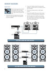
HOOKUP DIAGRAMS .............................................. 6<br />
CONVERTING TO RACKMOUNT MODE .................... 9<br />
SWITCHING POSITIONS ................................... 9<br />
PATCHBAY DESCRIPTION ......................................... 10<br />
E-Z INTERFACE ............................................... 10<br />
MIC/LINE INPUTS ON EVERY CHANNEL* ......... 10<br />
MIC INPUTS ................................................... 10<br />
PHANTOM POWER ........................................ 10<br />
LINE INPUTS .................................................. 11<br />
TRIM ............................................................. 11<br />
INSERT* ......................................................... 11<br />
DIRECT OUT* ................................................. 11<br />
SPLIT MONITORING ....................................... 12<br />
AUX SEND OUTPUTS ...................................... 12<br />
EFFECTS: SERIAL OR PARALLEL? ..................... 13<br />
AUX RETURN INPUTS ..................................... 13<br />
SUB OUTS* .................................................... 13<br />
C-R OUTS (CONTROL ROOM OUTPUTS)* .... 14<br />
PHONES OUTPUT ........................................... 14<br />
TAPE OUTPUT* .............................................. 14<br />
TAPE INPUT* ................................................. 14<br />
MAIN INSERT ................................................. 15<br />
MAIN OUTS ................................................... 15<br />
MONO OUTPUT ............................................. 15<br />
MONO LEVEL* ............................................... 15<br />
POWER CONNECTION .................................... 15<br />
FUSE .............................................................. 15<br />
POWER SWITCH ............................................ 16<br />
POWER LED ................................................... 16<br />
PHANTOM SWITCH ........................................ 16<br />
PHANTOM LED* ............................................. 16<br />
BNC LAMP SOCKET ........................................ 16<br />
CHANNEL STRIP DESCRIPTION .............................. 17<br />
“U” LIKE UNITY GAIN .................................. 17<br />
FADER ........................................................... 17<br />
ASSIGN (1-2, 3-4, L-R)* ................................ 17<br />
SOLO ............................................................. 18<br />
–20 (SOLO) LED*........................................... 18<br />
OL (MUTE) LED*............................................. 18<br />
MUTE ............................................................. 19<br />
PAN ............................................................... 19<br />
3-BAND MID-SWEEP EQ* ............................... 19<br />
LOW CUT* ..................................................... 20<br />
AUX ............................................................... 20<br />
PRE ............................................................... 21<br />
5/6 SHIFT ..................................................... 21<br />
OUTPUT SECTION DESCRIPTION ............................ 22<br />
MAIN L-R MIX FADER .................................... 22<br />
<strong>VLZ</strong> MIX ARCHITECTURE ................................ 22<br />
SUB FADERS* ................................................. 22<br />
ASSIGN TO MAIN MIX* ................................. 22<br />
TAPE IN (LEVEL)*............................................ 23<br />
TAPE TO MAIN MIX* ...................................... 23<br />
SOURCE* ....................................................... 23<br />
C-R/PHONES* ............................................... 23<br />
MODE (NORMAL (AFL)/LEVEL SET (PFL))* ....... 24<br />
LEVEL SET LED* .............................................. 24<br />
SOLO (LEVEL)* ............................................... 24<br />
RUDE SOLO LIGHT .......................................... 24<br />
METERS ......................................................... 25<br />
AUX TALK ...................................................... 25<br />
AUX SEND (MASTER)* ................................... 25<br />
AUX SEND SOLO* .......................................... 26<br />
AUX RETURNS (LEVEL) ................................... 26<br />
EFFECTS TO MONITOR* ................................. 26<br />
MAIN MIX TO SUBS (AUX RET 3)* ................. 26<br />
1-2/3-4 (AUX RET 3)* .................................. 26<br />
C-R/PHNS ONLY (AUX RET 4)* ...................... 27<br />
RETURNS SOLO .............................................. 27<br />
<strong>CR1604</strong>-<strong>VLZ</strong> MODIFICATIONS ............................. 28<br />
<strong>CR1604</strong>-<strong>VLZ</strong> BLOCK DIAGRAM ............................ 30<br />
GAIN STRUCTURE DIAGRAM ................................. 31<br />
SPECIFICATIONS .................................................... 32<br />
SERVICE INFO ....................................................... 33<br />
APPENDIX: Glossary ............................................. 34<br />
APPENDIX: Connections ......................................... 42<br />
APPENDIX: Balanced Lines, Phantom Powering,<br />
Grounding and Other Arcane Mysteries .................. 46<br />
* NEW! IMPROVED!<br />
LOADED WITH<br />
PROFESSIONAL FEATURES!<br />
For those of you accustomed to the original,<br />
classic CR-1604, do not be daunted by all the<br />
new features — we added them just for you!<br />
Asterisked items indicate features that we’ve<br />
added to the New Improved <strong>CR1604</strong>-<strong>VLZ</strong>.<br />
5
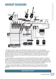
Studio Monitors<br />
Keyboard, or other line-level input<br />
OL<br />
PWR<br />
ON<br />
OFF<br />
,OL<br />
PWR<br />
ON<br />
OFF<br />
HIGH RESOLUTION<br />
STUDIO MONITOR<br />
HIGH RESOLUTION<br />
STUDIO MONITOR<br />
6<br />
Cassette or DAT<br />
Stereo EQ w/Compressor<br />
CH<br />
1<br />
Bass Preamp<br />
FULL SYMMETRY DUAL DIFFERENTIAL HIGH CURRENT DESIGN<br />
CH<br />
2<br />
Guitar Effects<br />
Drum<br />
Machine<br />
out<br />
in<br />
out<br />
in<br />
Stereo Power Amplifier<br />
R L L L R L R L<br />
16 15 14 13 12 11 10 9 8 7 6 5 4 3<br />
R R<br />
STEREO MONO<br />
2 1<br />
SUB OUTS C/R OUT TAPE TAPE MAIN MAIN OUT<br />
BAL/UNBAL BAL/UNBAL OUT IN INSERT BAL/UNBAL<br />
CHANNEL INPUTS<br />
AUX RETURNS<br />
AUX SENDS<br />
DIRECT OUT<br />
CHANNEL INSERTS<br />
3 2 1<br />
BAL/UNBAL<br />
BAL/UNBAL<br />
R L R L R L 6 5 4 3 2 1 8 7 6 5 4 3 2 1 16 15 14 13 12 11 10 9 8 7 6 5 4 3 2 1<br />
1 2 3 4<br />
PHONES<br />
OUT<br />
4<br />
L<br />
R<br />
8-track outputs<br />
<strong>CR1604</strong>-<strong>VLZ</strong> 8-Track Tracking<br />
HOOKUP DIAGRAMS<br />
out<br />
Digital<br />
8-track<br />
Digital Delay<br />
in<br />
Stereo Compressor<br />
Mono in / stereo out<br />
Reverb
Keyboard, or other line-level input<br />
Right PA Speaker<br />
Left PA Speaker<br />
Stereo EQ<br />
Recorder<br />
Multitrack<br />
Keyboard, or other line-level input<br />
out<br />
in<br />
out<br />
in<br />
Stereo<br />
Compressor<br />
Guitar Effects<br />
Drum<br />
Machine<br />
FULL SYMMETRY DUAL DIFFERENTIAL HIGH CURRENT DESIGN<br />
Optional Live Recording<br />
CH<br />
2<br />
CH<br />
1<br />
Stereo<br />
Power Amplifier<br />
CD Player<br />
NOTE: for mono PA, use<br />
mono output to feed FOH.<br />
5<br />
6<br />
7<br />
8<br />
9<br />
10<br />
11<br />
12<br />
13<br />
14<br />
1 2 3 4<br />
2 1<br />
3<br />
4<br />
CHANNEL INPUTS<br />
PHONES<br />
OUT<br />
CHANNEL INSERTS<br />
R L L L R L R L<br />
16 15<br />
R R<br />
STEREO MONO<br />
SUB OUTS C/R OUT TAPE TAPE MAIN MAIN OUT<br />
BAL/UNBAL BAL/UNBAL OUT IN INSERT BAL/UNBAL<br />
AUX RETURNS<br />
AUX SENDS<br />
DIRECT OUT<br />
3 2 1<br />
BAL/UNBAL<br />
BAL/UNBAL<br />
R L R L R L 6 5 4 3 2 1 8 7 6 5 4 3 2 1<br />
4<br />
16 15 14 13 12 11 10 9 8 7 6 5 4 3 2 1<br />
L<br />
R<br />
<strong>CR1604</strong>-<strong>VLZ</strong> Stereo P.A.<br />
Digital Delay<br />
Mono EQ<br />
Mono EQ<br />
Mono in / stereo out<br />
Reverb<br />
,<br />
Stereo Compressor<br />
Stereo Compressor<br />
Stage Monitor<br />
7<br />
Stage Monitor ,
Video Deck<br />
out<br />
8<br />
Video Deck<br />
Studio Monitors<br />
Video Deck<br />
CD Player<br />
Multi-VCR<br />
Video Switcher<br />
with Time Code<br />
Interface<br />
OL<br />
PWR<br />
ON<br />
OFF<br />
OL<br />
PWR<br />
ON<br />
OFF<br />
HIGH RESOLUTION<br />
STUDIO MONITOR<br />
HIGH RESOLUTION<br />
STUDIO MONITOR<br />
in<br />
Keyboard, or other line-level input<br />
Sampler<br />
Computer<br />
with Audio Card<br />
FULL SYMMETRY DUAL DIFFERENTIAL HIGH CURRENT DESIGN<br />
CH<br />
2<br />
CH<br />
1<br />
Stereo<br />
Power Amplifier<br />
Master<br />
Video<br />
3<br />
4<br />
5<br />
6<br />
7<br />
8<br />
9<br />
10<br />
11<br />
12<br />
13<br />
14<br />
1 2 3 4<br />
2 1<br />
CHANNEL INPUTS<br />
PHONES<br />
OUT<br />
CHANNEL INSERTS<br />
R L L L R L R L<br />
16 15<br />
R R<br />
STEREO MONO<br />
SUB OUTS C/R OUT TAPE TAPE MAIN MAIN OUT<br />
BAL/UNBAL BAL/UNBAL OUT IN INSERT BAL/UNBAL<br />
AUX RETURNS<br />
AUX SENDS<br />
DIRECT OUT<br />
3 2 1<br />
BAL/UNBAL<br />
BAL/UNBAL<br />
R L R L R L 6 5 4 3 2 1 8 7 6 5 4 3 2 1<br />
4<br />
<strong>CR1604</strong>-<strong>VLZ</strong> Video Setup<br />
16 15 14 13 12 11 10 9 8 7 6 5 4 3 2 1<br />
L<br />
R<br />
Digital Delay<br />
Mono in / stereo out<br />
Reverb<br />
Stereo Compressor
CONVERTING TO RACKMOUNT MODE<br />
Not only is the new <strong>CR1604</strong>-<strong>VLZ</strong> a compact,<br />
professional-quality tabletop mixer, it’s rackmountable!<br />
Its unique rotating input pod<br />
makes this possible.<br />
One of the things that revolutionized the compact<br />
mixer industry was the “convertible pod”<br />
found on the original, classic CR-1604. Using<br />
an ordinary Phillips screwdriver, the mixer<br />
could be converted from desktop mode (as it<br />
comes from the factory) to rackmount mode.<br />
Fear not. We wouldn’t dare take that feature<br />
out of the New Improved <strong>CR1604</strong>-<strong>VLZ</strong>. It’s<br />
still there and still takes just a few minutes<br />
with your screwdriver. Here’s how it’s done:<br />
1. Remove ALL the cords from the mixer —<br />
audio, power, lamps, everything.<br />
2. Place the mixer, face down, on a clean soft<br />
surface, like a blanket or very large dog.<br />
3. Remove the four screws securing the cable<br />
cover and set the plate aside.<br />
4. Replace two of the screws; the ones at the<br />
pod end of the mixer .<br />
5. Remove two pod-mounting screws on each<br />
side of the mixer .<br />
6. Gently pull the pod away from the slots, rotate<br />
it, and place it, tabs first, into the rackmount<br />
tabs , located on the underside of the<br />
main chassis. Be careful not to constrict or<br />
pinch any of the ribbon or power cables.<br />
7. Carefully install the podmounting<br />
screws in their new<br />
locations .<br />
8. Install the rack ears that came<br />
with the mixer. They can be installed<br />
in either of two depths:<br />
mixer’s surface flush with<br />
the rack rails, like ordinary<br />
rackmount equipment, or<br />
mixer’s surface sunken into<br />
the rack, to protect the<br />
knobs from being bumped.<br />
flush mount<br />
An optional accessory called the ROTOPOD-<br />
<strong>VLZ</strong> is available and can be used in desktop or<br />
rackmount installations. It will put the patchbay<br />
jacks on the same plane as all the knobs, buttons<br />
and faders. This is a lifesaver in applications that<br />
demand frequent repatching, and costs a heck of a<br />
lot less than an external patchbay, not to mention<br />
all the interface and patch cords: . Please<br />
visit your dealer for more exciting details. Be<br />
sure to order the “<strong>VLZ</strong>” version so you don’t<br />
end up with the one for the classic CR-1604!<br />
SWITCHING POSITIONS<br />
You may have noticed the white stripes printed<br />
just above most of the pushbutton switches on<br />
your <strong>CR1604</strong>-<strong>VLZ</strong>. We’ve put them there to<br />
make it easier for you to see if the switch is<br />
engaged (down). Here’s how they work:<br />
With the mixer in desktop mode, you’ll be<br />
sitting just in front of it, viewing the control<br />
panel at an oblique angle. When a switch is<br />
disengaged (up), the button will hide the<br />
white stripe from your field of vision. When<br />
you engage the switch, the stripe will suddenly<br />
appear. Although it may not seem obvious at<br />
first, you’ll soon find that the indicator stripe<br />
really helps you determine switch positions at<br />
a glance. Clever, ain’t it?<br />
remove<br />
screws<br />
remove<br />
plate<br />
remove<br />
screws<br />
rackmount<br />
tab slots<br />
replace<br />
screws<br />
rotate<br />
pod replace<br />
screws<br />
sunken<br />
9
BAL<br />
UN-<br />
BAL<br />
120 VAC 50/60 Hz 20W<br />
315mA/250V SLO-BLO<br />
MIC 16<br />
POWER<br />
PHANTOM<br />
At the risk of stating the obvious, this is<br />
where you plug everything in: microphones,<br />
line-level instruments and effects, and the ultimate<br />
destination for your sound: a tape<br />
recorder, PA system, etc. A few of the features<br />
described in this section are on top of the<br />
mixer, but most are out back on the “pod.”<br />
E-Z INTERFACE<br />
Concerned about levels,<br />
balancing, impedances, polarity,<br />
or other interface<br />
goblins? Don’t be. On your<br />
<strong>CR1604</strong>-<strong>VLZ</strong>, you can patch anything almost<br />
anywhere, with nary a care. Here’s why:<br />
• Every input and output is balanced<br />
(except insert, phones and RCA jacks).<br />
• Every input and output will also accept<br />
unbalanced lines (except XLR jacks).<br />
• Every input is designed to accept virtually<br />
any output impedance.<br />
• The main left and right mix outputs can<br />
deliver 28dBu into as low as a 600 ohm load.<br />
• All the other outputs can deliver 22dBu<br />
into as low as a 600 ohm load.<br />
• All the outputs are in phase with the inputs.<br />
All we ask is that you perform the Level-Setting<br />
Procedure every time you patch in a new<br />
sound source. So stop worrying and start mixing!<br />
MIC/LINE INPUTS ON EVERY CHANNEL<br />
The original CR-1604 had six mic/line channels<br />
and ten line-only channels. That was fine<br />
for most applications, but live sound users<br />
were forced to go out and buy the XLR-10 mic<br />
input add-on module. No more. Each and every<br />
channel on the New Improved <strong>CR1604</strong>-<strong>VLZ</strong> has<br />
the legendary <strong>Mackie</strong> mic/line input circuit.<br />
It’s like getting a free XLR-10 with your mixer!<br />
MIC INPUTS<br />
We use phantom-powered, balanced microphone<br />
inputs just like the big studio megaconsoles,<br />
for exactly the same reason: This<br />
kind of circuit is excellent at rejecting hum<br />
10<br />
O<br />
+6<br />
PATCHBAY DESCRIPTION<br />
INSERT INSERT INSERT INSERT INSERT INSERT INSERT INSERT INSERT INSERT INSERT INSERT<br />
LINE<br />
16 LINE 15 LINE 14 LINE 13 LINE 12 LINE 11 LINE 10 LINE 9 LINE 8 LINE 7 LINE 6 LINE 5<br />
BAL<br />
UN-<br />
BAL<br />
CAUTION:<br />
TO REDUCE THE RISK OF<br />
FIRE REPLACE WITH SAME<br />
TYPE FUSE AND RATING<br />
BAL<br />
UN-<br />
BAL<br />
MIC 15 MIC 14 MIC 13 MIC 12 MIC 11 MIC 10 MIC 9 MIC 8 MIC 7 MIC 6 MIC 5<br />
and noise. You can plug in almost any kind of<br />
mic that has a standard XLR-type male mic<br />
connector. Always be sure to perform the<br />
Level-Setting Procedure . To learn how signals<br />
are routed from these inputs: . If you<br />
wire your own, connect them like this:<br />
SHIELD<br />
HOT<br />
COLD<br />
SHIELD<br />
COLD 3<br />
HOT<br />
3<br />
1<br />
2<br />
2<br />
2<br />
3 1<br />
1<br />
SHIELD<br />
COLD<br />
HOT<br />
Pin 1 = ground or shield<br />
Pin 2 = positive (+ or hot)<br />
Pin 3 = negative (– or cold)<br />
Professional ribbon, dynamic, and condenser<br />
mics will all sound excellent through<br />
these inputs. The <strong>CR1604</strong>-<strong>VLZ</strong>’s mic inputs<br />
will handle almost any kind of mic level you<br />
can toss at them, without overloading.<br />
PHANTOM POWER<br />
Most condenser mics require phantom power,<br />
where the mixer sends low-current DC voltage to<br />
the mic’s electronics through the same wires<br />
that carry audio. The <strong>CR1604</strong>-<strong>VLZ</strong>’s phantom<br />
power is globally controlled by the PHANTOM<br />
switch on the rear panel .<br />
Semipro condenser mics often have batteries<br />
to accomplish the same thing. “Phantom”<br />
owes its name to an ability to be “unseen” by<br />
dynamic mics (Shure ® SM57/SM58, for instance)<br />
that don’t need external power and<br />
aren’t affected by it anyway.<br />
Unless you know for certain<br />
it is safe to do so,<br />
never plug single-ended<br />
(unbalanced) microphones,<br />
instruments or<br />
electronic devices into the MIC input jacks if<br />
the phantom power is on.<br />
MAIN OUT<br />
BAL/UNBAL<br />
MAIN INSERT TAPE<br />
INPUT<br />
TAPE<br />
OUTPUT<br />
C-R OUTS<br />
BAL/UNBAL<br />
SUB OUTS<br />
BAL/UNBAL<br />
AUX RETURN<br />
BAL/UNBAL<br />
AUX SEND<br />
BAL/UNBAL<br />
DIRECT OUT<br />
BAL/UNBAL<br />
L<br />
L<br />
L<br />
3<br />
1<br />
4 3<br />
2<br />
1<br />
5<br />
3 1<br />
7 5 3<br />
BAL<br />
UN-<br />
BAL<br />
R<br />
MONO<br />
BAL<br />
UN-<br />
BAL<br />
L<br />
R<br />
R<br />
BAL<br />
UN-<br />
BAL<br />
L<br />
R<br />
BAL<br />
UN-<br />
BAL<br />
R<br />
BAL<br />
UN-<br />
BAL<br />
4 2<br />
BAL<br />
UN-<br />
BAL<br />
L L L<br />
(MONO)<br />
(MONO)<br />
(MONO)<br />
R R R<br />
BAL<br />
UN-<br />
BAL<br />
BAL<br />
UN-<br />
BAL<br />
BAL<br />
UN-<br />
BAL<br />
6 4 2<br />
BAL<br />
UN-<br />
BAL<br />
INSERT INSERT INSERT<br />
LINE<br />
INSERT<br />
4 LINE 3 LINE 2 LINE 1<br />
BAL<br />
UN-<br />
BAL<br />
8 6 4<br />
BAL<br />
UN-<br />
BAL<br />
BAL<br />
UN-<br />
BAL<br />
MIC 4 MIC 3 MIC 2 MIC 1<br />
1<br />
2<br />
PATENT PENDING
LINE INPUTS<br />
These 1 /4" jacks share circuitry (but not<br />
phantom power) with the mic preamps. You<br />
can use these inputs for virtually any signal<br />
you’ll come across, from instrument levels as<br />
low as –40dB to operating levels of –10dBV to<br />
+4dBu, as there is 40dB of gain available via<br />
the TRIM knob . Always be sure to perform<br />
the Level-Setting Procedure .<br />
To learn how signals are routed from these<br />
inputs: . To connect balanced lines to these<br />
inputs, use a 1 /4" tip-ring-sleeve (TRS) plug,<br />
the type found on some stereo headphones:<br />
Tip = positive (+ or hot)<br />
Ring = negative (– or cold)<br />
Sleeve = shield or ground<br />
To connect unbalanced lines to these inputs,<br />
use a 1 /4" mono (TS) phone plug or<br />
standard instrument cable:<br />
Tip = signal (+)<br />
Sleeve = ground<br />
RING<br />
SLEEVE<br />
TRIM<br />
Yes it’s true, these controls are not located<br />
in the patchbay section at all. They’re found<br />
along the top row of knobs in the channel strip<br />
section. But their purpose is so closely linked<br />
with the MIC and LINE input jacks that we<br />
couldn’t bear to separate them. Here’s why:<br />
Every time you plug something into a MIC or<br />
LINE input jack, you should perform the Level-<br />
Setting Procedure , and that procedure is<br />
basically “how to use the TRIM knob.”<br />
TRIM adjusts the input sensitivity of the<br />
MIC and LINE inputs. This allows signals from<br />
the outside world to be adjusted to optimal<br />
internal operating levels.<br />
Through the XLR jack (MIC), there will be<br />
10dB of gain with the knob fully down, ramping<br />
to 60dB of gain fully up.<br />
Through the 1 /4" input (LINE), there is 10dB<br />
of attenuation fully down and 40dB of gain fully<br />
up, with a “U” (unity gain) mark at 9:00.<br />
TIP<br />
TIP<br />
SLEEVE<br />
SLEEVE RING<br />
SLEEVE<br />
TIP<br />
TIP<br />
SLEEVE<br />
TIP<br />
RING<br />
TIP<br />
SLEEVE<br />
This 10dB of attenuation can be very handy<br />
when you are inserting a signal that is very hot,<br />
or you want to add a lot of EQ gain, or both.<br />
Without this “virtual pad,” a scenario like that<br />
might lead to channel clipping.<br />
INSERT<br />
These 1 /4" jacks are for connecting serial<br />
effects processors such as compressors, equalizers,<br />
de-essers, or filters . The INSERT point is<br />
after the TRIM control, but before the channel’s<br />
EQ, LOW CUT, fader and MUTE controls. Insert<br />
cables must be wired thusly:<br />
tip ring sleeve<br />
(TRS plug)<br />
This plug connects to one of the<br />
mixer’s Channel Insert jacks.<br />
SEND to processor<br />
“tip”<br />
“ring”<br />
RETURN from processor<br />
Tip = send (output to effects device)<br />
Ring = return (input from effects device)<br />
Sleeve = common ground<br />
Even though channels 1–8 already have<br />
DIRECT OUT jacks , INSERT jacks can also<br />
be used as channel direct outputs; post-TRIM,<br />
pre-LOW CUT, and pre-EQ. Here’s three ways<br />
you can use the INSERT jacks:<br />
MONO PLUG<br />
Channel Insert jack<br />
Direct out with no signal interruption to master.<br />
Insert only to first “click.”<br />
MONO PLUG<br />
Channel Insert jack<br />
Direct out with signal interruption to master.<br />
Insert all the way in to the second “click.”<br />
STEREO<br />
PLUG<br />
Channel Insert jack<br />
For use as an effects loop.<br />
(TIP = SEND to effect, RING = RETURN from effect.)<br />
DIRECT OUT<br />
Found only on channels 1–8, these 1 /4" jacks<br />
deliver the signal from the very end of the<br />
channel path; post-TRIM, post-EQ, post-LOW<br />
CUT, post-fader and post-MUTE. They are the<br />
key player in “split monitoring,” making the<br />
<strong>CR1604</strong>-<strong>VLZ</strong> perfect for an 8-track studio. To<br />
wire your own cables: .<br />
11<br />
TRIM 1<br />
U<br />
AUX<br />
1<br />
2<br />
3<br />
EQ<br />
O<br />
PRE<br />
U<br />
-15 +15<br />
LOW CUT<br />
75 Hz<br />
18dB/OCT<br />
PAN<br />
5<br />
4 6<br />
200<br />
5/6<br />
SHIFT<br />
-15<br />
-15<br />
-10dBV<br />
MIC GAIN<br />
10 60<br />
+10dB -40dB<br />
O<br />
O<br />
O<br />
O<br />
U<br />
O<br />
O<br />
U<br />
O<br />
U<br />
U<br />
U<br />
800<br />
+15<br />
+15<br />
+15<br />
+15<br />
+15<br />
+15<br />
12k<br />
HI<br />
MID<br />
2k<br />
100 8k<br />
U LOW<br />
80Hz<br />
L R<br />
1<br />
MUTE<br />
OL<br />
-20<br />
SOLO<br />
O<br />
1–2<br />
3–4<br />
L - R
12<br />
SPLIT MONITORING<br />
With split monitoring, you use the first eight<br />
channels for your sound sources: vocal mics,<br />
drum mics, keyboard/synth outputs, guitar<br />
effects outputs, that sort of thing. From there,<br />
the channels manipulate the sound, but are<br />
not assigned to the output section. Instead,<br />
they’re patched from the channel’s DIRECT<br />
OUT jacks to the corresponding multitrack<br />
input (DIRECT OUT 1 to multitrack input 1,<br />
2 to 2, 3 to 3, etc.). The signals will now be recorded<br />
or pass directly through the multitrack,<br />
depending on each track’s record-ready status.<br />
multitrack<br />
machine<br />
sound sources<br />
1–8 9–16<br />
direct<br />
outputs<br />
group<br />
outputs<br />
The outputs of the multitrack are then<br />
patched to the next eight LINE inputs on the<br />
<strong>CR1604</strong>-<strong>VLZ</strong> (multitrack out 1 to LINE input 9,<br />
2 to 10, 3 to 11, etc.). Aha! That’s why it says<br />
“TRACK 1” next to channel 9’s fader, “TRACK 2”<br />
next to channel 10, and so forth. These channels<br />
(9–16) will be assigned to the mixer’s<br />
output section, delivering the signals to their<br />
ultimate destination, which may be your<br />
mixdown 2-track, your control room system,<br />
or your headphones.<br />
But let’s not forget that the <strong>CR1604</strong>-<strong>VLZ</strong> is a<br />
4-bus mixer. These buses lead to the SUB<br />
OUTS , and are designed to accomplish the<br />
task of getting channels to the multitrack without<br />
using the direct outputs.<br />
For example, a channel is assigned to<br />
SUB OUT 1. SUB OUT 1’s output is patched to<br />
multitrack input 1. From there, the multitrack<br />
output goes to the mixer’s channel 9 LINE input,<br />
as we just discussed. (Hot tip: To feed an 8-track<br />
deck with 4 sub outputs, simply use Y-cords:<br />
SUB OUT 1 feeds tracks 1 and 5, 2 feeds 2 and<br />
6, 3 feeds 3 and 7, and 4 feeds 4 and 8. Tracks in<br />
record mode will accept the signal, and tracks in<br />
safe mode will ignore the signal.)<br />
The advantages: You can assign any channel<br />
to any track, without repatching. You can assign<br />
multiple channels to one track and control<br />
the overall level of that subgroup . You can’t<br />
bounce tracks without this feature.<br />
Perhaps the best method is to do both: Use<br />
the SUB OUTS to feed multichannel submixes<br />
(like a drum kit) to some of the tracks, and<br />
the DIRECT OUT jacks to feed single-channel<br />
signals (like bass guitar) to the other tracks.<br />
The point is that you never listen directly to<br />
the source channels (1–8). You listen to the<br />
monitor channels (9–16) and they’re listening to<br />
the multitrack that is listening to the source<br />
channels. The main advantage is that you won’t<br />
be forced to constantly repatch your multitrack<br />
— just set it up and forget it. You’ll also know for<br />
certain that the signals are indeed getting to the<br />
multitrack, since you’re constantly listening to it.<br />
Another method of interfacing a multitrack is<br />
called inline monitoring, and requires a mixing<br />
console dedicated to that, like the <strong>Mackie</strong><br />
8•Bus. Each of its channels is actually two channels:<br />
one carrying the mic/line sound source and<br />
the other carrying the multitrack output.<br />
AUX SEND OUTPUTS<br />
These 1 /4" jacks usually patch to the inputs<br />
of your parallel effects devices or to the inputs<br />
of your stage monitor amps. To learn how<br />
signals are routed to these outputs: . To wire<br />
your own cables: .
BAL<br />
UN-<br />
BAL<br />
120 VAC 50/60 Hz 20W<br />
315mA/250V SLO-BLO<br />
MIC 16<br />
POWER<br />
PHANTOM<br />
EFFECTS: SERIAL OR PARALLEL?<br />
MAIN OUT<br />
BAL/UNBAL<br />
MAIN INSERT TAPE<br />
INPUT<br />
TAPE<br />
OUTPUT<br />
C-R OUTS<br />
BAL/UNBAL<br />
SUB OUTS<br />
BAL/UNBAL<br />
AUX RETURN<br />
BAL/UNBAL<br />
AUX SEND<br />
BAL/UNBAL<br />
DIRECT OUT<br />
BAL/UNBAL<br />
L<br />
L<br />
L<br />
3<br />
1<br />
4 3<br />
2<br />
1<br />
5<br />
3 1<br />
7 5 3<br />
You’ve heard us carelessly toss around the<br />
terms “serial” and “parallel.” Here’s what we<br />
mean by them:<br />
“Serial” means that the entire signal leaves<br />
the mixer (INSERT send), is routed through the<br />
effects device, and returns to the mixer<br />
(INSERT return). Examples: compressor, limiter,<br />
graphic equalizer. Line-level sources can<br />
also be patched through a serial effects device<br />
before or after the mixer.<br />
“Parallel” means that a portion of the signal<br />
in the mixer is tapped off to the device (AUX<br />
SEND), processed, and returned to the mixer<br />
(AUX RETURN) to be mixed with the original<br />
“dry” signal. This way, multiple channels can<br />
all make use of the same effects device.<br />
Examples: reverb, digital delay.<br />
AUX RETURN INPUTS<br />
This is where you connect the outputs of your<br />
parallel effects devices (or extra audio sources).<br />
They’ll accept just about any pro or semipro<br />
effects device on the market. To learn how signals<br />
are routed from these inputs: . To wire<br />
your own cables: .<br />
R<br />
MONO<br />
O<br />
+6<br />
L<br />
R<br />
R<br />
L<br />
R<br />
INSERT INSERT INSERT INSERT INSERT INSERT INSERT INSERT INSERT INSERT INSERT INSERT<br />
LINE<br />
16 LINE 15 LINE 14 LINE 13 LINE 12 LINE 11 LINE 10 LINE 9 LINE 8 LINE 7 LINE 6 LINE 5<br />
BAL<br />
UN-<br />
BAL<br />
CAUTION:<br />
TO REDUCE THE RISK OF<br />
FIRE REPLACE WITH SAME<br />
TYPE FUSE AND RATING<br />
BAL<br />
UN-<br />
BAL<br />
BAL<br />
UN-<br />
BAL<br />
MIC 15 MIC 14 MIC 13 MIC 12 MIC 11 MIC 10 MIC 9 MIC 8 MIC 7 MIC 6 MIC 5<br />
Serial Device (e.g., Compressor)<br />
Insert<br />
Send<br />
BAL<br />
UN-<br />
BAL<br />
BAL<br />
UN-<br />
BAL<br />
BAL<br />
UN-<br />
BAL<br />
R<br />
BAL<br />
UN-<br />
BAL<br />
4 2<br />
BAL<br />
UN-<br />
BAL<br />
Mono: If you have an effects device with a<br />
mono output (one cord), plug that into L input<br />
of an AUX RETURN and leave the right<br />
input unplugged. That way, the signal will be<br />
sent to both sides, magically appearing in the<br />
center as a mono signal.<br />
SUB OUTS<br />
These 1 /4" jacks are usually patched to the inputs<br />
of a multitrack deck, or to secondary<br />
amplifiers in a complex installation. To learn<br />
how signals are routed to these outputs: .<br />
To wire your own cables: .<br />
Double Busing<br />
L L L<br />
(MONO)<br />
(MONO)<br />
(MONO)<br />
R R R<br />
BAL<br />
UN-<br />
BAL<br />
6 4 2<br />
How on earth do you get four jacks to<br />
feed eight tracks? To feed an 8-track deck<br />
with only four SUB OUTS, simply use four<br />
Y-cords:<br />
• SUB OUT 1 feeds tracks 1 and 5<br />
• SUB OUT 2 feeds tracks 2 and 6<br />
• SUB OUT 3 feeds tracks 3 and 7<br />
• SUB OUT 4 feeds tracks 4 and 8<br />
Tracks in record mode will accept the signal,<br />
and tracks in safe mode will ignore the signal.<br />
It’s that easy.<br />
Signal Processor<br />
Dry Signal Processed<br />
Signal<br />
Parallel Device (e.g., Reverb)<br />
Dry Signal(s)<br />
Aux<br />
Send<br />
Signal Processor<br />
Channel Path<br />
Insert<br />
Return<br />
Aux<br />
Return<br />
Wet Signal<br />
Dry Signal(s)<br />
BAL<br />
UN-<br />
BAL<br />
Output<br />
Section<br />
Mix<br />
Stage<br />
BAL<br />
UN-<br />
BAL<br />
Processed<br />
Signal<br />
BAL<br />
UN-<br />
BAL<br />
INSERT INSERT INSERT<br />
LINE<br />
4 LINE 3 LINE 2 LINE 1<br />
BAL<br />
UN-<br />
BAL<br />
13<br />
8 6 4<br />
BAL<br />
UN-<br />
BAL<br />
BAL<br />
UN-<br />
BAL<br />
INSERT<br />
MIC 4 MIC 3 MIC 2 MIC 1<br />
1<br />
2<br />
PATENT PENDING
This method is exactly<br />
the same as the doublebusing<br />
feature found in<br />
other mixers. Built-in double<br />
busing is nothing more than<br />
Y-cords living inside the mixer instead of<br />
hanging out the back. If we had room for the<br />
extra jacks, we would have thrown them in,<br />
but we don’t, so we didn’t. Sonically, there is<br />
no difference whatsoever.<br />
Y-cord advice: Do not use the stereo “headphone-to-left/right”<br />
splitter adapters. Use the type<br />
that send the same signal to two places; the tip of<br />
the source plug feeds the tips of both destination<br />
plugs (Radio Shack ® #42-2150, for instance.)<br />
C-R OUTS (CONTROL ROOM OUTPUTS)<br />
These 1 /4" jacks are usually patched to the<br />
inputs of your control room amplifier or a<br />
headphone distribution amplifier. To learn<br />
how signals are routed to these outputs: .<br />
To wire your own cables: .<br />
14<br />
PHONES OUTPUT<br />
The <strong>CR1604</strong>-<strong>VLZ</strong>’s stereo 1 /4" phones jack<br />
will drive any standard headphone to very loud<br />
levels. Walkperson-type phones can also be<br />
used with an appropriate adapter. To learn<br />
how signals are routed to these outputs: . If<br />
you’re wiring your own cable for the PHONES<br />
output, follow standard conventions:<br />
TIP<br />
Tip = left channel<br />
Ring = right channel<br />
Sleeve = common ground<br />
LEFT<br />
RIGHT<br />
RING<br />
ASSIGN TO MAIN MIX<br />
LEFT<br />
RIGHT<br />
LEFT<br />
RIGHT<br />
SLEEVE<br />
LEFT<br />
RIGHT<br />
1 2 3 4<br />
dB<br />
10<br />
5<br />
U<br />
5<br />
10<br />
20<br />
30<br />
40<br />
50<br />
60<br />
O<br />
SLEEVE RING<br />
PHONES<br />
MAIN<br />
L-R MIX<br />
dB<br />
10<br />
5<br />
U<br />
5<br />
10<br />
20<br />
30<br />
40<br />
50<br />
60<br />
O<br />
TIP<br />
RING<br />
TIP<br />
SLEEVE<br />
WARNING: When we say<br />
the headphone amp is<br />
loud, we’re not kidding. It<br />
can cause permanent ear<br />
damage. Even intermediate<br />
levels may be painfully loud with some<br />
earphones. BE CAREFUL!<br />
Always turn the C-R/PHONES knob all the<br />
way down before connecting headphones. Keep<br />
it down until you’ve put the phones on. Then<br />
turn it up slowly. Why? “Engineers who fry<br />
their ears find themselves with short careers.”<br />
TAPE OUTPUT<br />
These unbalanced RCA jacks tap the MAIN<br />
MIX outputs to make simultaneous recording<br />
and PA work more convenient. Connect these<br />
to your 2-track recorder’s inputs. To learn how<br />
signals are routed to these outputs: .<br />
Mono: If you want to feed a mono signal to<br />
your tape deck or other device, simply use the<br />
1 /4" MONO output jack . Alternatively, use<br />
an RCA Y-cord to combine the TAPE OUTPUT<br />
jacks (Radio Shack ® #42-2435, for instance).<br />
Do not attempt this with any other outputs on<br />
the <strong>CR1604</strong>-<strong>VLZ</strong>.<br />
TAPE INPUT<br />
These unbalanced RCA jacks are designed<br />
to work with semipro as well as pro recorders.<br />
Connect your 2-track tape recorder’s outputs<br />
here, using standard hi-fi RCA cables. To learn<br />
how signals are routed from these inputs: .<br />
Use these jacks for convenient playback of<br />
your mixes. You’ll be able to review a mix, and<br />
then rewind and try another pass without<br />
repatching or disturbing the mixer levels. You<br />
can also use these jacks with a portable tape<br />
or CD player to feed music to a PA system<br />
between sets .<br />
WARNING: Pushing TAPE<br />
TO MAIN MIX in the output<br />
section can create a<br />
feedback path between<br />
TAPE INPUT and TAPE<br />
OUTPUT. Make sure your tape deck is not<br />
in record, record-pause or input monitor<br />
mode when you engage this switch, or<br />
make sure the TAPE IN level knob is fully<br />
counterclockwise (off).
MAIN INSERT<br />
These 1 /4" jacks are for connecting serial<br />
effects such as compressors, equalizers, deessers,<br />
or filters . The INSERT point is after<br />
the mix amps, but before the MAIN L-R MIX<br />
fader. Insert cables must be wired thusly:<br />
tip ring sleeve<br />
(TRS plug)<br />
This plug connects to one of the<br />
mixer’s Channel Insert jacks.<br />
SEND to processor<br />
“tip”<br />
“ring”<br />
RETURN from processor<br />
Tip = send (output to effects device)<br />
Ring = return (input from effects device)<br />
Sleeve = common ground (connect shield to<br />
all three sleeves)<br />
MAIN OUTS<br />
These 1 /4" jacks are usually patched to the<br />
inputs of your 2-track mixdown deck (unless<br />
you’ve chosen to use the TAPE OUTPUT RCA<br />
jacks), or to the house amplifier during live<br />
sound sessions. To learn how signals are<br />
routed to these outputs: . To use these outputs<br />
to drive balanced inputs, connect 1 /4" TRS<br />
(Tip-Ring-Sleeve) phone plugs like this:<br />
Tip = + (hot)<br />
Ring = – (cold)<br />
Sleeve = ground<br />
To use these outputs to drive unbalanced<br />
inputs, connect 1 RING<br />
TIP<br />
/4" TS (Tip-Sleeve) phone<br />
plugs like this:<br />
Tip = signal<br />
Sleeve = ground<br />
RING<br />
SLEEVE RING<br />
SLEEVE<br />
MONO OUTPUT<br />
It happens to everybody sooner or later:<br />
The forces that govern your world will demand<br />
a monaural output from your painstakinglycreated<br />
stereo panorama. The last thing you<br />
want to do is start twirling all your carefullyplaced<br />
PAN settings to one side. What to do?<br />
Stick a cord in this 1 /4" jack, hand the other<br />
end to Mr. Mono, and you’re done. He’s got his<br />
mono mix and you’ve still got your stereo mix.<br />
The MONO output is nothing more than a mix<br />
of the left and right MAIN MIX.<br />
MONO LEVEL<br />
So, Mr. Mono comes running back, screaming<br />
about the mono mix being so loud that his<br />
camcorder is melting. Just reach for this knob<br />
and turn it down a bit. Just the thing for send-<br />
TIP<br />
TIP<br />
SLEEVE<br />
SLEEVE<br />
SLEEVE<br />
TIP<br />
TIP<br />
TIP<br />
SLEEVE<br />
ing mono signals to mic inputs like camcorders,<br />
telephone interface boxes, even answering<br />
machines. With the pot all the way up (fully<br />
clockwise), you’ll have 6dB of extra gain with<br />
unity gain halfway between the one and two<br />
o’clock positions.<br />
POWER CONNECTION<br />
Just in case you lose the cord provided with<br />
the <strong>CR1604</strong>-<strong>VLZ</strong>, its power jack accepts a standard<br />
3-prong IEC cord like those found on<br />
most professional recorders, musical instruments,<br />
and computers. At the other end of our<br />
cord is — get this — a plug! Not a black cube<br />
or, as we’re fond of calling them, a “wall wart.”<br />
We did this for some very good reasons:<br />
The <strong>CR1604</strong>-<strong>VLZ</strong> has sophisticated power<br />
requirements that a wall wart cannot provide.<br />
Wall warts are inconvenient, fragile, radiate huge<br />
hum fields, hog extra jacks on your power strip<br />
and get in the way. If you lose a wall wart, you’re<br />
in trouble, but if you lose the <strong>CR1604</strong>-<strong>VLZ</strong>’s power<br />
cord, you can get a new one at any electronics,<br />
music, or computer store. You can even buy them<br />
at Radio Shack ® (part # 278-1257).<br />
Plug the <strong>CR1604</strong>-<strong>VLZ</strong> into any standard<br />
grounded (3-pin) AC outlet or into a power<br />
strip of proper voltage.<br />
WARNING: Disconnecting<br />
the plug’s ground pin can<br />
be dangerous. Please<br />
don’t do it.<br />
FUSE<br />
The <strong>CR1604</strong>-<strong>VLZ</strong> is fused for your (and its<br />
own) protection. If you suspect a blown fuse,<br />
disconnect the power cord, pull the fuse drawer<br />
out (located just below the cord receptacle)<br />
and replace the fuse with a 1A SLO BLO, 5x20mm,<br />
available at electronics stores or your dealer<br />
(or a 500mA [0.5 amps] SLO BLO 5x20mm if<br />
your <strong>CR1604</strong>-<strong>VLZ</strong> is a 220V-240V unit).<br />
BAL<br />
UN-<br />
BAL<br />
120 VAC 50/60 Hz 20W<br />
315mA/250V SLO-BLO<br />
MIC 16<br />
POWER<br />
PHANTOM<br />
MAIN OUT<br />
BAL/UNBAL<br />
MAIN INSERT TAPE<br />
INPUT<br />
TAPE<br />
OUTPUT<br />
C-R OUTS<br />
BAL/UNBAL<br />
L<br />
L<br />
L<br />
R<br />
MONO<br />
O<br />
INSERT INSERT INSERT INSERT INSERT INSERT INSERT<br />
LINE<br />
+6<br />
R<br />
R<br />
16 LINE 15 LINE 14 LINE 13 LINE 12 LINE 11 LINE 10<br />
BAL<br />
UN-<br />
BAL<br />
CAUTION:<br />
TO REDUCE THE RISK OF<br />
FIRE REPLACE WITH SAME<br />
TYPE FUSE AND RATING<br />
BAL<br />
UN-<br />
BAL<br />
BAL<br />
UN-<br />
BAL<br />
BAL<br />
UN-<br />
BAL<br />
MIC 15 MIC 14 MIC 13 MIC 12 MIC 11 MIC 10<br />
L<br />
BAL<br />
UN-<br />
BAL<br />
L<br />
R<br />
BAL<br />
UN-<br />
BAL<br />
15<br />
R
BAL<br />
UN-<br />
BAL<br />
120 VAC 50/60 Hz 20W<br />
315mA/250V SLO-BLO<br />
MIC 16<br />
POWER<br />
PHANTOM<br />
16<br />
POWER SWITCH<br />
If this one isn’t self-explanatory, we give up.<br />
You can leave this switch on all the time; the<br />
<strong>CR1604</strong>-<strong>VLZ</strong> is conservatively designed, so heat<br />
buildup isn’t a problem even in 24-hour-a-day<br />
operation. There’s nothing that will burn out or<br />
get used up. You may notice that the <strong>CR1604</strong>-<br />
<strong>VLZ</strong>’s “pod” feels quite warm (the pod is the<br />
chassis that contains the jacks). This is perfectly<br />
normal.<br />
POWER LED<br />
You’ve probably already figured this out, but<br />
if the POWER switch is on, this LED (lightemitting<br />
diode), located in the output section,<br />
will light. If the switch is off, well, you get the<br />
idea. If the POWER switch is on and the LED<br />
does not glow, one of three things has happened:<br />
Somebody tripped over the power cord<br />
and yanked it from the outlet, your electricity<br />
has been turned off due to nonpayment, or the<br />
fuse has blown .<br />
PHANTOM SWITCH<br />
The PHANTOM switch controls the phantom<br />
power supply for condenser microphones as<br />
discussed at the start of this section . When<br />
turned on (or off), the phantom power circuitry<br />
takes a few moments for voltage to ramp up (or<br />
down). This is also perfectly normal. For an<br />
even closer look, refer to Appendix C.<br />
O<br />
+6<br />
PHANTOM LED<br />
INSERT INSERT INSERT INSERT INSERT INSERT INSERT INSERT INSERT INSERT INSERT INSERT<br />
LINE<br />
16 LINE 15 LINE 14 LINE 13 LINE 12 LINE 11 LINE 10 LINE 9 LINE 8 LINE 7 LINE 6 LINE 5<br />
BAL<br />
UN-<br />
BAL<br />
CAUTION:<br />
TO REDUCE THE RISK OF<br />
FIRE REPLACE WITH SAME<br />
TYPE FUSE AND RATING<br />
BAL<br />
UN-<br />
BAL<br />
MIC 15 MIC 14 MIC 13 MIC 12 MIC 11 MIC 10 MIC 9 MIC 8 MIC 7 MIC 6 MIC 5<br />
Located right next to the POWER LED in the<br />
output section, this is just to let you know which<br />
way you have the PHANTOM switch set. If your<br />
dynamic mics work and your condensers don’t,<br />
chances are this LED is off, so turn it on.<br />
You’ll notice that when you turn the phantom<br />
power off, the LED stays on for a while.<br />
This is a natural phenomenon — the LED is<br />
actually a yellow voltmeter telling you that the<br />
phantom power takes time to ramp itself down<br />
to zero volts. So, if you’ve turned phantom<br />
power off to connect something to the mic inputs,<br />
wait until the yellow LED stops glowing<br />
and then make your connections safely.<br />
BNC LAMP SOCKET<br />
Located in the top right corner of the output<br />
section, this 12V socket will drive any<br />
standard BNC-type lamp (a Littlite ® #12G or<br />
#12G-HI (high-intensity), for instance).<br />
MAIN OUT<br />
BAL/UNBAL<br />
MAIN INSERT TAPE<br />
INPUT<br />
TAPE<br />
OUTPUT<br />
C-R OUTS<br />
BAL/UNBAL<br />
SUB OUTS<br />
BAL/UNBAL<br />
AUX RETURN<br />
BAL/UNBAL<br />
AUX SEND<br />
BAL/UNBAL<br />
DIRECT OUT<br />
BAL/UNBAL<br />
L<br />
L<br />
L<br />
3<br />
1<br />
4 3<br />
2<br />
1<br />
5<br />
3 1<br />
7 5 3<br />
BAL<br />
UN-<br />
BAL<br />
R<br />
MONO<br />
BAL<br />
UN-<br />
BAL<br />
L<br />
R<br />
R<br />
BAL<br />
UN-<br />
BAL<br />
L<br />
R<br />
BAL<br />
UN-<br />
BAL<br />
R<br />
BAL<br />
UN-<br />
BAL<br />
4 2<br />
BAL<br />
UN-<br />
BAL<br />
L L L<br />
(MONO)<br />
(MONO)<br />
(MONO)<br />
R R R<br />
BAL<br />
UN-<br />
BAL<br />
BAL<br />
UN-<br />
BAL<br />
1<br />
2<br />
1<br />
2<br />
BAL<br />
UN-<br />
BAL<br />
O<br />
O<br />
+10<br />
AUX<br />
SENDS<br />
SOLO<br />
SOLO<br />
PHAN PWR<br />
1<br />
2<br />
3<br />
4<br />
6 4 2<br />
BAL<br />
UN-<br />
BAL<br />
O<br />
INSERT INSERT INSERT<br />
LINE<br />
O<br />
O<br />
U<br />
O<br />
U<br />
+20<br />
+20<br />
STEREO AUX RETURNS<br />
INSERT<br />
4 LINE 3 LINE 2 LINE 1<br />
BAL<br />
UN-<br />
BAL<br />
1<br />
2<br />
ASSIGN OPTIONS<br />
MAIN MIX<br />
TO SUBS<br />
C-R / PHNS<br />
ONLY<br />
O<br />
O<br />
O<br />
O<br />
O<br />
O<br />
U<br />
U<br />
+10<br />
O<br />
O<br />
O<br />
U<br />
U<br />
O<br />
+20<br />
+20<br />
TM<br />
<strong>CR1604</strong>-<strong>VLZ</strong><br />
16 -CHANNEL MIC/LINE MIXER<br />
U<br />
U<br />
+15<br />
+15<br />
8 6 4<br />
BAL<br />
UN-<br />
BAL<br />
LAMP<br />
TO AUX<br />
SEND 1<br />
EFFECTS TO<br />
MONITORS<br />
TO AUX<br />
SEND 2<br />
1–2<br />
3–4<br />
RETURNS<br />
SOLO<br />
12V<br />
0.5A<br />
LEFT RIGHT<br />
BAL<br />
UN-<br />
BAL<br />
MIC 4 MIC 3 MIC 2 MIC 1<br />
1<br />
2<br />
PATENT PENDING
CHANNEL STRIP DESCRIPTION<br />
The sixteen channel strips look alike and<br />
function identically. The only difference is that<br />
the eight on the left have DIRECT OUT jacks<br />
and the eight on the right don’t. We’ll start<br />
at the bottom and work our way up.<br />
“U” LIKE UNITY GAIN<br />
<strong>Mackie</strong> mixers have a “U”<br />
symbol on almost every level<br />
control. This “U” stands for<br />
“unity gain,” meaning no<br />
change in signal level. Once you have performed<br />
the Level-Setting Procedure , you<br />
can set every control at “U” and your signals<br />
will travel through the mixer at optimal levels.<br />
What’s more, all the labels on our controls<br />
are measured in decibels (dB), so you’ll know<br />
what you’re doing level-wise if you choose to<br />
change a control’s settings.<br />
You won’t have to check it here and check it<br />
there, as you would with some other mixers. In<br />
fact, some don’t even have any reference to<br />
actual dB levels at all! Ever seen those “0–10”<br />
fader markings? We call these AUMs (Arbitrary<br />
Units of Measurement), and they mean nothing<br />
in the real world. You were smart — you<br />
bought a <strong>Mackie</strong>.<br />
FADER<br />
The fader is almost the last control in a<br />
channel’s signal path. It’s placed after the EQ<br />
and MUTE controls (post-EQ /post-MUTE and<br />
before the PAN control (pre-PAN). The “U”<br />
mark, about three-quarters of the way up,<br />
indicates unity gain, meaning no increase or<br />
decrease of signal level. All the way up provides<br />
an additional 10dB, should you need to<br />
boost a section of a song. If you find that the<br />
overall level is too quiet or too loud with a<br />
fader near unity, you’ll want to confirm the<br />
TRIM setting by performing the Level-Setting<br />
Procedure .<br />
A Clean Fade<br />
Faders are not rocket<br />
science — they operate by<br />
dragging a metal pin (the<br />
wiper) across a carbon-based<br />
strip (the track). It is possible for airborne<br />
crud to land on the track. Should that happen,<br />
you may hear scratchy noises or signal dropouts<br />
as the wiper stumbles over the crud. Do<br />
all you can to keep airborne crud out of your<br />
profession. Use air conditioned rooms whenever<br />
possible, avoid smoking near the mixer,<br />
keep food and drink away from the mixer, and<br />
for pity’s sake, never put the mixer in your<br />
kitchen! We also recommend “exercising” the<br />
faders — give them a few full-travel excursions<br />
once a week or so, and that will help<br />
scare the crud away. We do not recommend<br />
spray cleaners.<br />
ASSIGN (1–2, 3–4, L–R)<br />
Alongside each channel fader are four buttons,<br />
labeled SOLO, 1–2, 3–4 and L–R. The<br />
latter three are collectively referred to as channel<br />
assignment switches. 1, 3 and L are the left<br />
sides of these stereo pairs, and 2, 4 and R are<br />
the right sides. Used in conjunction with the<br />
channel’s PAN knob , these switches determine<br />
the destination of a channel’s signal:<br />
With the PAN knob set at the center detent,<br />
the left and right sides receive equal signal<br />
levels. To feed only one side or the other, just<br />
turn the PAN knob accordingly.<br />
If you’re doing a mixdown to a 2-track, simply<br />
engage the L–R switch on each channel<br />
that you want to hear, and they’ll be sent to the<br />
MAIN L-R MIX. If you want to create a subgroup<br />
of certain channels, engage either the<br />
1–2 or 3–4 switches instead of the L–R, and<br />
they’ll be sent to the appropriate subgroup faders<br />
. From there, the subgroups can be sent<br />
back to the MAIN L-R MIX , allowing you to<br />
use the subgroup faders as a master control for<br />
those channels.<br />
17<br />
TRIM 1<br />
U<br />
AUX<br />
1<br />
2<br />
3<br />
EQ<br />
PAN<br />
O<br />
PRE<br />
U<br />
5<br />
4 6<br />
200<br />
5/6<br />
SHIFT<br />
-15<br />
-15<br />
O<br />
O<br />
U<br />
O<br />
O<br />
U<br />
O<br />
U<br />
U<br />
800<br />
+15<br />
+15<br />
+15<br />
+15<br />
+15<br />
2k<br />
100 8k<br />
U LOW<br />
80Hz<br />
-15<br />
-10dBV<br />
MIC GAIN<br />
10 60<br />
+10dB -40dB<br />
LOW CUT<br />
75 Hz<br />
18dB/OCT<br />
O<br />
O<br />
U<br />
+15<br />
+15<br />
L R<br />
1<br />
MUTE<br />
O<br />
12k<br />
HI<br />
MID<br />
OL<br />
-20<br />
SOLO<br />
1–2<br />
3–4<br />
L - R
TRIM 1<br />
U<br />
AUX<br />
1<br />
2<br />
3<br />
EQ<br />
PRE<br />
-15 +15<br />
LOW CUT<br />
75 Hz<br />
18dB/OCT<br />
PAN<br />
5<br />
4 6<br />
200<br />
O<br />
U<br />
5/6<br />
SHIFT<br />
-15<br />
-15<br />
-10dBV<br />
MIC GAIN<br />
10 60<br />
+10dB -40dB<br />
O<br />
O<br />
O<br />
O<br />
O<br />
O<br />
O<br />
U<br />
U<br />
U<br />
U<br />
U<br />
800<br />
+15<br />
+15<br />
+15<br />
+15<br />
+15<br />
+15<br />
12k<br />
HI<br />
MID<br />
2k<br />
100 8k<br />
U LOW<br />
80Hz<br />
L R<br />
1<br />
MUTE<br />
O<br />
OL<br />
-20<br />
SOLO<br />
1–2<br />
3–4<br />
L - R<br />
If you’re printing new tracks or bouncing existing<br />
ones, you’ll also use the 1–2 and 3–4<br />
switches, but not the L–R switch. Here, you<br />
don’t want the subgroups sent back into the<br />
MAIN L-R MIX, but sent out, via the SUB OUTS<br />
jacks, to your multitrack inputs . However, if<br />
you’re printing tracks via the DIRECT OUT<br />
jacks , all the channel assignment switches<br />
should be disengaged (up).<br />
The <strong>CR1604</strong>-<strong>VLZ</strong> is what we call a “true<br />
4-bus mixer.” Each channel can be assigned or<br />
unassigned to any of the subgroups without affecting<br />
the other subgroups or settings within<br />
the channel, and each subgroup has its own<br />
master fader and dedicated output . In<br />
fact, since there are 4 subgroups and the MAIN<br />
L–R MIX, it’s actually a true 6-bus mixer. We<br />
could have named it the CR1606-<strong>VLZ</strong>. Darn!<br />
SOLO<br />
This lovable switch allows you to check<br />
signals through your PHONES output or C-R<br />
OUTS without having to assign them to the<br />
L-R, 1-2 or 3-4 mixes. You can solo as many<br />
channels as you like. SOLO does not interrupt<br />
any of the other channels, buses or outputs —<br />
that’s called nondestructive solo. Not only that,<br />
via the MODE switch , the <strong>CR1604</strong>-<strong>VLZ</strong>’s<br />
solo system comes in two flavors: NORMAL<br />
(AFL) (sometimes called SIP, or solo-in-place)<br />
and LEVEL SET (PFL) (sometimes called PFL,<br />
or pre-fader-listen).<br />
During NORMAL (AFL) mode, the soloed<br />
channel’s signal is sent directly to the C-R OUTS,<br />
PHONES output, and meter display just as it<br />
would sound to the channel’s assignment<br />
switches: post-EQ, post-fader and post-PAN.<br />
The only difference is that SOLO works regardless<br />
of the channel’s assignment positions,<br />
and that makes it really handy — you can<br />
check out a channel before you assign it.<br />
NORMAL (AFL) is the preferred mode during<br />
mixdown: If the channel has some<br />
midrange boost at 4.236kHz, is panned a smidgen<br />
to the left, and its fader is at –5.385dB,<br />
that’s exactly what you’ll hear if you SOLO during<br />
NORMAL (AFL) mode. It’s just as if you<br />
took the time to MUTE all the other channels.<br />
LEVEL SET (PFL) solo is the key player in the<br />
all-important Level-Setting Procedure . It’ll<br />
send the channel’s actual internal levels to the<br />
meters so you’ll know just what’s going on, levelwise.<br />
This procedure should be performed every<br />
time a new sound source is patched into a<br />
channel’s MIC or LINE input jacks.<br />
18<br />
LEVEL SET (PFL) is also the preferred mode<br />
for SR (sound reinforcement, or live sound), to<br />
preview channels before they are let into the<br />
mix. It won’t give you stereo placement, but will<br />
give you signal even if the fader is pulled down.<br />
Remember, LEVEL SET (PFL) taps the channel<br />
signal before the fader. If you have a<br />
channel’s fader set way below “U” (unity gain),<br />
SOLO won’t know that and will send a unity<br />
gain signal to the C-R OUTS, PHONES output<br />
and meter display. That may result in a startling<br />
level boost at these outputs, depending on the<br />
position of the SOLO level knob .<br />
In a nutshell, soloed channels are sent to<br />
the SOURCE mix , that ultimately feeds your<br />
C-R OUTS, PHONES output and meter display.<br />
Whenever SOLO is engaged, all SOURCE selections<br />
(MAIN MIX, 1–2, 3–4 and TAPE) are<br />
defeated, to allow the soloed channel to do just<br />
that — SOLO!<br />
–20 (SOLO) LED<br />
An LED that does two completely different<br />
things! Saves space, but requires some explanation.<br />
First, the “–20” part: Often referred to<br />
as “signal activity,” this LED will flicker in time<br />
with the signal present in that channel. It’s<br />
handy for confirming that a channel is indeed<br />
active, and may also lend a clue as to what the<br />
signal is. For instance, a kick drum will cause<br />
the LED to pulse in time with the drum, and a<br />
synth pad will cause it glow a bit more steadily.<br />
Now for the “SOLO” part. When a channel’s<br />
SOLO switch is engaged, this LED will glow<br />
steadily, without flickering. It will also be<br />
brighter than it would be as a –20 indicator. In<br />
conjunction with the RUDE SOLO LIGHT ,<br />
you can find a rogue SOLO switch very quickly.<br />
OL (MUTE) LED<br />
Another LED that does two completely different<br />
things! First, the “OL” part: “OL” means<br />
overload, or clip. You don’t want that to happen.<br />
Ever. Clipping can happen to any mixer — it’s<br />
the point where the signal’s voltage exceeds the<br />
supply voltages that power the circuitry. The<br />
<strong>CR1604</strong>-<strong>VLZ</strong>’s OL LED will come on just before<br />
clipping, so if you see it, take immediate action:<br />
Perform the Level-Setting Procedure . If that<br />
doesn’t help, check for excessive use of EQ<br />
boost or fader gain. Like the –20 LED, it will<br />
tend to flicker in time with that channel’s signal.<br />
Now for the “MUTE” part. Assuming your<br />
levels are set correctly, the OL LED will never
come on as a result of clipping. That’s pretty<br />
boring. So, to liven things up, this LED will<br />
glow steadily when that channel’s MUTE<br />
switch is engaged.<br />
If you need a quick reference to these LEDs,<br />
write this on the back of your hand:<br />
name color flickering glowing<br />
–20 (SOLO) green signal is present channel is soloed<br />
OL (MUTE) red channel is clipping channel is muted<br />
MUTE<br />
Engaging a channel’s MUTE switch provides<br />
the same results as turning the fader all<br />
the way down: Any channel assignment to<br />
L-R, 1-2 or 3-4 will be interrupted. All the post<br />
AUX sends will be silenced, as will the<br />
DIRECT OUT signals on channels 1 through<br />
8. And of course, that fun-loving OL (MUTE)<br />
LED will commence to glow. The PRE AUX<br />
sends , channel INSERT send and SOLO<br />
(in LEVEL SET (PFL) mode) will continue to<br />
function during MUTE.<br />
Depending on the audio content in a channel,<br />
engaging its MUTE switch may cause a<br />
slight popping sound. This is not a problem<br />
within the mixer, and it can be avoided: Simply<br />
engage the LOW CUT switch on each<br />
channel (unless its low frequency content is<br />
vitally important, such as a kick drum or bass<br />
guitar). LOW CUT eliminates subsonic debris,<br />
which causes the pop, and its effect is<br />
usually transparent.<br />
PAN<br />
PAN adjusts the amount of channel signal<br />
sent to the left versus the right outputs. Pan determines<br />
the fate of the L-R assignment,<br />
subgroups 1–2 and 3–4, and the SOLO (in<br />
LEVEL SET (PFL) mode). With the PAN knob<br />
hard left, the signal will feed the left MAIN L-R<br />
MIX, subgroup 1, subgroup 3 and left NORMAL<br />
(AFL) solo mode (assuming their assignment<br />
switches are engaged). With the knob hard<br />
right, signal feeds the right MAIN L-R MIX, subgroup<br />
2, subgroup 4 and right NORMAL (AFL)<br />
solo mode. With the PAN knob set somewhere<br />
in-between left and right, the signal will be divided<br />
between the left and right busses.<br />
Stereo Sources<br />
Your life will be easier if you follow this<br />
standard convention: When patching stereo<br />
sound sources to a mixer, always plug the left<br />
signal into an “odd” channel (1, 3, 5, etc.) and<br />
the right signal into the adjacent “even” channel<br />
(2, 4, 6, etc.). Then pan the odd channel<br />
hard left and the even channel hard right.<br />
CONSTANT LOUDNESS ! ! !<br />
The <strong>CR1604</strong>-<strong>VLZ</strong>’s PAN<br />
controls employ a design<br />
called “Constant Loudness.”<br />
It has nothing to do with<br />
living next to a freeway. As you turn the PAN<br />
knob from left to right (thereby causing the<br />
sound to move from the left to the center to<br />
the right), the sound will appear to remain at<br />
the same volume (or loudness).<br />
If you have a channel panned hard left (or<br />
right) and reading 0dB, it must dip down about<br />
4dB on the left (or right) when panned center.<br />
To do otherwise, like those Brand X mixers,<br />
would make the sound appear much louder<br />
when panned center.<br />
3-BAND MID-SWEEP EQ<br />
The <strong>CR1604</strong>-<strong>VLZ</strong> has a 3-band, mid-sweep<br />
equalization: LOW shelving at 80Hz, MID sweep<br />
peaking from 100Hz to 8kHz, and HI shelving at<br />
12kHz. It’s probably all the EQ you’ll ever need!<br />
(Shelving means that the circuitry boosts or<br />
cuts all frequencies past the specified frequency.<br />
For example, the <strong>CR1604</strong>-<strong>VLZ</strong>’s LOW EQ boosts<br />
bass frequencies starting at 80Hz and continuing<br />
down to the lowest note you never heard.<br />
Peaking means that certain frequencies form a<br />
“hill” around the center frequency.)<br />
The LOW EQ provides up to 15dB boost or cut<br />
at 80Hz. The circuit is flat (no boost or cut) at the<br />
center detent position. This frequency represents<br />
the punch in bass drums, bass guitar, fat synth<br />
patches, and some really serious male singers.<br />
+15<br />
+10<br />
+5<br />
0<br />
–5<br />
–10<br />
–15<br />
20Hz 100Hz 1kHz 10kHz 20kHz<br />
Used in conjunction with the LOW CUT<br />
switch , you can boost the LOW EQ without<br />
injecting a ton of subsonic debris into the mix.<br />
We recommend using the LOW CUT feature on<br />
all channels, except low frequency signals, like<br />
kick drums and bass guitars.<br />
The MID EQ , or “midrange,” has a fixed<br />
bandwidth of 1.5 octaves. The MID knob sets<br />
the amount of boost or cut, up to 15dB, and is<br />
effectively bypassed at then center detent. The<br />
frequency knob sets the center frequency,<br />
sweepable from 100Hz to 8kHz.<br />
19<br />
TRIM 1<br />
U<br />
AUX<br />
1<br />
2<br />
3<br />
EQ<br />
O<br />
PRE<br />
U<br />
-15 +15<br />
LOW CUT<br />
75 Hz<br />
18dB/OCT<br />
PAN<br />
5<br />
4 6<br />
200<br />
5/6<br />
SHIFT<br />
-15<br />
-15<br />
-10dBV<br />
MIC GAIN<br />
10 60<br />
+10dB -40dB<br />
O<br />
O<br />
O<br />
O<br />
O<br />
O<br />
O<br />
U<br />
U<br />
U<br />
U<br />
U<br />
800<br />
+15<br />
+15<br />
+15<br />
+15<br />
+15<br />
+15<br />
12k<br />
HI<br />
MID<br />
2k<br />
100 8k<br />
U LOW<br />
80Hz<br />
L R<br />
1<br />
MUTE<br />
O<br />
OL<br />
-20<br />
SOLO<br />
1–2<br />
3–4<br />
L - R
TRIM 1<br />
U<br />
AUX<br />
1<br />
2<br />
3<br />
EQ<br />
-15 +15<br />
LOW CUT<br />
75 Hz<br />
18dB/OCT<br />
PAN<br />
5<br />
4 6<br />
200<br />
PRE<br />
5/6<br />
SHIFT<br />
-15<br />
-15<br />
-10dBV<br />
MIC GAIN<br />
10 60<br />
+10dB -40dB<br />
O<br />
O<br />
O<br />
O<br />
O<br />
O<br />
O<br />
U<br />
U<br />
U<br />
U<br />
O<br />
U<br />
U<br />
800<br />
+15<br />
+15<br />
+15<br />
+15<br />
+15<br />
+15<br />
2k<br />
100 8k<br />
U LOW<br />
80Hz<br />
L R<br />
1<br />
MUTE<br />
O<br />
12k<br />
HI<br />
OL<br />
-20<br />
SOLO<br />
MID<br />
1–2<br />
3–4<br />
L - R<br />
20<br />
+15<br />
+10<br />
+5<br />
0<br />
–5<br />
–10<br />
–15<br />
+15<br />
+10<br />
+5<br />
0<br />
–5<br />
–10<br />
–15<br />
20Hz 100Hz 1kHz 10kHz 20kHz<br />
20Hz 100Hz 1kHz 10kHz 20kHz<br />
Most of the root and lower harmonics that<br />
define a sound are located in the 100Hz–8kHz<br />
frequency range, and you can create drastic<br />
changes with these two knobs. Many engineers<br />
use MID EQ to cut midrange frequencies, not<br />
boost them. One popular trick is to set the MID<br />
fully up, turn the frequency knob until you find<br />
a point where it sounds just terrible, then back<br />
the MID down into the cut range, causing<br />
those terrible frequencies to disappear. Sounds<br />
silly, but it works. Sometimes.<br />
The HI EQ provides you up to 15dB boost or<br />
cut at 12kHz, and it is also flat at the detent. Use<br />
it to add sizzle to cymbals, an overall sense of<br />
transparency, or an edge to keyboards, vocals, guitar<br />
and bacon frying. Turn it down a little to<br />
reduce sibilance or to mask tape hiss.<br />
+15<br />
+10<br />
+5<br />
0<br />
–5<br />
–10<br />
–15<br />
20Hz 100Hz 1kHz 10kHz 20kHz<br />
With too much EQ, you can screw things up<br />
royally. We’ve designed a lot of boost and cut<br />
into each equalizer circuit because we know<br />
everyone will occasionally need that. But if you<br />
max the EQ on every channel, you’ll get mix<br />
mush. Equalize subtly and use the left sides of<br />
the knobs (cut), as well as the right (boost). If<br />
you find yourself repeatedly using full boost or<br />
cut, consider altering the sound source, such<br />
as placing a mic differently, trying a different<br />
kind of mic, changing the strings, or gargling.<br />
LOW CUT<br />
The LOW CUT switch, often referred to as a<br />
high pass filter (all depends on how you look<br />
at it), cuts bass frequencies below 75Hz at a<br />
rate of 18dB per octave. This ain’t no thrown-in<br />
dime-store filter — an 18dB per octave curve<br />
requires an elaborate circuit. Nothing but the<br />
best for you.<br />
We recommend that you use LOW CUT on every<br />
sound source except kick drum, bass guitar,<br />
bassy synth patches, or recordings of earthquakes.<br />
These aside, there isn’t much down there<br />
that you want to hear, and filtering it out makes<br />
the low stuff you do want much more crisp and<br />
tasty. Not only that, but low cut can help reduce<br />
the possibility of feedback in live situations, and it<br />
helps to conserve amplifier power.<br />
With LOW CUT, you can safely boost LOW<br />
EQ . Many times, bass shelving eq can really<br />
benefit voices. Trouble is, adding LOW EQ also<br />
boosts the subsonic debris: Stage rumble, mic<br />
handling clunks, wind noise and breath pops.<br />
LOW CUT removes all that debris so you can<br />
boost the LOW EQ without frying your woofer.<br />
Here’s a frequency curve of LOW EQ combined<br />
with LOW CUT:<br />
+15<br />
+10<br />
+5<br />
0<br />
–5<br />
–10<br />
–15<br />
20Hz 100Hz 1kHz 10kHz 20kHz<br />
AUX 1, 2, 3, & 4<br />
These four knobs tap a portion of each<br />
channel’s signal, mix them together and send<br />
them to the AUX SEND outputs . They are<br />
off when turned fully down, deliver unity gain<br />
at the center detent, and can provide up to<br />
15dB of gain turned fully up. Chances are you’ll<br />
never need this extra gain, but it’s nice to<br />
know it’s there if you do.<br />
The AUX SEND output are then patched to<br />
parallel effects processor inputs or stage<br />
monitor amp inputs. AUX SENDS 1 and 2 levels<br />
are controlled not only by the channel’s<br />
AUX knobs, but also by the AUX SEND master<br />
knobs .<br />
AUX SENDS can also be used to generate<br />
separate mixes for recording or “mix-minuses”<br />
for broadcast. By using AUX 1 or 2 in the PRE<br />
mode , these mix levels can be obtained independently<br />
of a channel’s fader settings.
We recommend going into a stereo reverb in<br />
mono and returning in stereo. We have found<br />
that on most “stereo” reverbs, the second input<br />
just ties up an extra aux send and adds nothing<br />
to the sound. There are exceptions, so feel free<br />
to try it both ways. Should you choose to use two<br />
aux sends, use the “odd” AUX (1, 3 or 5) to feed<br />
its left input and the “even” AUX (2, 4 or 6) to<br />
feed the right input. Remember, if you’re also<br />
dealing with a stereo source signal, you’ll want<br />
to follow the sides — use the odd AUX on the<br />
channel carrying the left side and the even AUX<br />
on the channel carrying the right.<br />
PRE<br />
This switch determines the tap point of<br />
AUX 1 and 2. Generally, “post” sends are used<br />
to feed effects devices, and “pre” sends are<br />
used to feed your stage monitors. See the “Pre<br />
vs. Post” diagram below. AUX 3 through 6 are<br />
always in post mode.<br />
In post mode (switch up), AUX 1 and 2 will<br />
follow the EQ, LOW CUT, fader and MUTE settings.<br />
If you fade the channel, you fade the<br />
send. This is a must for effects sends, since you<br />
want the levels of your “wet” signals to follow<br />
the level of the “dry.”<br />
INPUT TRIM INSERT<br />
LOW<br />
CUT<br />
'PRE' SIGNAL<br />
Pre Vs. Post<br />
EQ<br />
In PRE mode (switch down), AUX 1 and 2<br />
follow the TRIM and LOW CUT settings only.<br />
EQ, PAN, fader and MUTE settings have no effect<br />
on the PRE sends. This is the preferred<br />
method for setting up stage monitor feeds —<br />
they’ll be controlled independently of the fader<br />
and mute moves.<br />
5/6 SHIFT<br />
Don’t let the fact that there’s only four AUX<br />
knobs per channel fool you — the <strong>CR1604</strong>-<strong>VLZ</strong><br />
has six AUX SENDs. With the 5/6 SHIFT switch<br />
up, the knobs labeled AUX 3 and AUX 4 deliver<br />
their signals to AUX SEND 3 and 4 outputs.<br />
With the shift switch down, the signals appear<br />
at the AUX SEND 5 and 6 outputs.<br />
We recommend that AUX SEND 3 and 4 be<br />
patched into your “utility” effects, like a short reverb<br />
and slap delay; effects you use all the time.<br />
Use AUX SEND 5 and 6 for “exotic” effects, like<br />
harmonizers and multi-tap delays; they are not<br />
likely to be used as often.<br />
MUTE<br />
FADER<br />
'POST' SIGNAL<br />
PAN ASSIGN<br />
PRE SWITCH<br />
AUX 1<br />
AUX 2<br />
21<br />
TRIM 1<br />
U<br />
AUX<br />
1<br />
2<br />
3<br />
EQ<br />
O<br />
PRE<br />
U<br />
-15 +15<br />
LOW CUT<br />
75 Hz<br />
18dB/OCT<br />
PAN<br />
5<br />
4 6<br />
200<br />
5/6<br />
SHIFT<br />
-15<br />
-15<br />
-10dBV<br />
MIC GAIN<br />
10 60<br />
+10dB -40dB<br />
O<br />
O<br />
O<br />
O<br />
U<br />
O<br />
O<br />
U<br />
O<br />
U<br />
U<br />
U<br />
800<br />
+15<br />
+15<br />
+15<br />
+15<br />
+15<br />
+15<br />
12k<br />
HI<br />
MID<br />
2k<br />
100 8k<br />
U LOW<br />
80Hz<br />
L R<br />
1<br />
MUTE<br />
OL<br />
-20<br />
SOLO<br />
O<br />
1–2<br />
3–4<br />
L - R
1<br />
2<br />
1<br />
2<br />
O<br />
U<br />
U<br />
O<br />
+10<br />
AUX<br />
SENDS<br />
SOLO<br />
SOLO<br />
PHAN PWR<br />
1<br />
2<br />
3<br />
4<br />
O<br />
O<br />
O<br />
U<br />
U<br />
U<br />
O<br />
+20<br />
+20<br />
1<br />
2<br />
ASSIGN OPTIONS<br />
MAIN MIX<br />
TO SUBS<br />
C-R / PHNS<br />
ONLY<br />
STEREO AUX RETURNS<br />
22<br />
O<br />
O<br />
O<br />
O<br />
O<br />
O<br />
+10<br />
C-R / PHONES<br />
SUBS 1–2<br />
SUBS 3–4<br />
MAIN MIX<br />
SOURCE<br />
O<br />
O<br />
O<br />
U<br />
O<br />
+20<br />
+20<br />
TAPE IN<br />
TAPE TAPE TO<br />
MAIN MIX<br />
LEFT<br />
RIGHT<br />
U<br />
LEFT<br />
RIGHT<br />
MAX<br />
SOLO<br />
U<br />
MODE<br />
NORMAL (AFL)<br />
LEVEL SET (PFL)<br />
ASSIGN TO MAIN MIX<br />
LEFT<br />
RIGHT<br />
TM<br />
<strong>CR1604</strong>-<strong>VLZ</strong><br />
16 -CHANNEL MIC/LINE MIXER<br />
O<br />
O<br />
MAX<br />
LEVEL<br />
SET<br />
1 2 3 4<br />
O<br />
O<br />
O<br />
U<br />
O<br />
+20<br />
O<br />
+15<br />
+15<br />
LAMP<br />
OUTPUT SECTION DESCRIPTION<br />
12V<br />
0.5A<br />
TO AUX<br />
SEND 1<br />
EFFECTS TO<br />
MONITORS<br />
TO AUX<br />
SEND 2<br />
O<br />
You’ve just learned about the<br />
input channels and how the signals<br />
get in and out. The signals<br />
come in via MIC and LINE input<br />
jacks, are manipulated by the<br />
channels, and then sent to the<br />
output section. In the output<br />
section, things get a bit more<br />
complicated, so put on your<br />
thinking caps.<br />
1–2<br />
3–4<br />
MAIN L-R MIX FADER<br />
RETURNS As the name implies, this<br />
SOLO<br />
fader controls the levels of<br />
LEFT RIGHT signals sent to the MAIN OUT<br />
CLIP<br />
28<br />
0 dB=0 dBu<br />
1 /4" TRS jacks and TAPE<br />
10<br />
OUTPUT RCA jacks . All<br />
7<br />
4<br />
channels and AUX RETURNs<br />
2<br />
that are assigned to the MAIN<br />
0<br />
2<br />
L-R MIX, not muted and not<br />
4<br />
turned fully down will appear<br />
7<br />
10<br />
20<br />
at the MAIN OUT. Before the<br />
main mix gets to this fader, the<br />
30<br />
RUDE<br />
SOLO<br />
LIGHT<br />
signals pass through the MAIN<br />
INSERT .<br />
The MAIN L-R MIX signals<br />
LEFT<br />
are off with the fader fully<br />
RIGHT<br />
PHONES<br />
MAIN<br />
L-R MIX<br />
down, the “U” marking is unity<br />
gain, and fully up provides<br />
dB<br />
10<br />
dB<br />
10 10dB additional gain. This ad-<br />
5<br />
5 ditional gain will typically<br />
U<br />
U never be needed, but once<br />
5<br />
5 again, it’s nice to know it’s<br />
10<br />
10 there. The fader itself is a ste-<br />
20<br />
20 reo version of the channel and<br />
30<br />
30 subgroup faders — same su-<br />
40<br />
50<br />
60<br />
40<br />
50<br />
60<br />
persmooth custom taper, same<br />
dead silence when turned fully<br />
down. This is the fader to pull<br />
down at the end of the song<br />
when you want “The Great Fade-Out.”<br />
<strong>VLZ</strong> MIX<br />
ARCHITECTURE<br />
When designing a mixing<br />
circuit, the lowest noise and<br />
best crosstalk specs are<br />
achieved by using Very Low Impedance (<strong>VLZ</strong>).<br />
To implement <strong>VLZ</strong> in a mixer, the power supply<br />
must be able to deliver plenty of current to the<br />
circuitry. That’s why those “wall wart” mixers are<br />
often noisy — they can’t power a <strong>VLZ</strong> circuit.<br />
At <strong>Mackie</strong>, audio quality is much more important<br />
than the price of wall warts. All of our<br />
mixers now employ <strong>VLZ</strong> and built-in power<br />
supplies that deliver more than enough current,<br />
resulting in sonic specifications that<br />
rival consoles upwards of $50,000!<br />
SUBGROUP FADERS<br />
As you might expect, these faders control the<br />
levels of signals sent to the SUB OUTS. All channels<br />
that are assigned to subgroups, not muted<br />
and not turned fully down will appear at the<br />
SUB OUTS. Unlike the MAIN OUT, the subgroup<br />
signals do not pass through an insert jack<br />
on their way to the subgroup faders. That’s no<br />
problem — should you want to send these signals<br />
through a serial effects processor, simply<br />
patch from the SUB OUTS to the effect’s input,<br />
and from the effect’s output to whatever the final<br />
destination is, usually a multitrack recorder.<br />
The subgroup signals is off when its fader is<br />
fully down, the “U” marking is unity gain, and<br />
fully up provides 10dB additional gain. Remember<br />
that if you’re treating two subgroups<br />
as a stereo pair, subgroup 1 and 2 for example,<br />
make sure that both subgroup faders “ride”<br />
together, to maintain the left/right balance.<br />
ASSIGN TO MAIN MIX<br />
One popular use of the subgroups is to use<br />
them as master faders for a group of channels<br />
on their way to the MAIN L-R MIX. Let’s say<br />
you’ve got a drum kit hogging up seven channels<br />
and you’re going to want to fade them out at a<br />
different rate than the other channels. You don’t<br />
want to try that with seven hands or seven fingers,<br />
so just un-assign these channels from L–R,<br />
reassign them to subgroup 1–2, engage the AS-<br />
SIGN TO MAIN MIX, LEFT on subgroup 1 and<br />
the ASSIGN TO MAIN MIX, RIGHT on subgroup<br />
2. Now you can ride the entire stereo drum mix<br />
with two faders — 1 and 2.<br />
If you engage just one ASSIGN TO MAIN<br />
MIX switch per subgroup (LEFT or RIGHT),<br />
the signal sent to the MAIN L-R MIX will be<br />
the same level as the SUB OUTS. If you want<br />
the subgroup to appear in the center of the<br />
main mix, engage both the ASSIGN TO MAIN<br />
MIX, LEFT and ASSIGN TO MAIN MIX, RIGHT<br />
switches. The signal will be sent to both sides,<br />
and will be attenuated just enough to preserve<br />
constant loudness , just like the<br />
channel PAN knobs when set center.
TAPE IN (LEVEL)<br />
This knob controls the level of the stereo signal<br />
coming from the TAPE INPUT RCA jacks. Its range<br />
is off when fully down, unity at the center detent,<br />
with 20dB additional gain turned fully up, which<br />
may come in handy if you’ve patched in a<br />
“walkperson” type device with wimpy output levels.<br />
After the TAPE IN level is determined, the stereo<br />
tape signal can be sent to either of two places —<br />
the MAIN L-R MIX or the SOURCE matrix .<br />
TAPE TO MAIN MIX<br />
Engaging this switch is just like engaging<br />
the L-R switch on a channel — the signal,<br />
stereo in this case, is sent to the MAIN MIX. It<br />
does not interrupt other signals, just adds itself<br />
to them. This switch can be very handy in a<br />
live sound situation when you want to play<br />
soothing elevator music to an anxious crowd.<br />
WARNING: Engaging<br />
TAPE TO MAIN MIX can<br />
create a feedback path between<br />
TAPE INPUT and<br />
TAPE OUTPUT. Make sure<br />
your tape deck is not in record, recordpause<br />
or input monitor mode when you<br />
engage this switch, or that the TAPE IN<br />
level knob is turned fully down.<br />
SOURCE<br />
Typically, the engineer sends the main mix<br />
to an audience (if live) or to a mixdown deck<br />
(if recording). But what if the engineer needs<br />
to hear something other than the main mix?<br />
With the New Improved <strong>CR1604</strong>-<strong>VLZ</strong>, the engineer<br />
has several choices of what to listen to.<br />
This is one of those tricky parts — have a<br />
double espresso first.<br />
Via the SOURCE switches, you can choose to<br />
listen to any combination of MAIN MIX, SUBS<br />
1-2, SUBS 3-4 and TAPE. Selections made in the<br />
SOURCE matrix deliver stereo signals to the<br />
C-R OUTS, PHONES output and meter display.<br />
These signals are tapped after their respective<br />
level controls — post-MAIN L-R MIX fader, post<br />
subgroup faders and post-TAPE IN knob. With<br />
no switches engaged, there will be no signal at<br />
these outputs and no meter indication, with two<br />
exceptions (SOLO / and AUX RETURN 4 ).<br />
One of those exceptions is the SOLO function<br />
/ . Regardless of the SOURCE matrix<br />
selection, engaging a SOLO switch will replace<br />
that selection with the SOLO signal, also sent<br />
to the C-R OUTS, PHONES output and meter<br />
display. This is what makes the Level-Setting<br />
Procedure so easy to do.<br />
Now you know how to select the signals you<br />
want to send to the engineer’s control room<br />
and/or phones. From there, these signals all pass<br />
through the same level control, aptly named:<br />
C-R/PHONES<br />
As you might expect, this knob controls the<br />
levels of both the stereo C-R OUTS and<br />
PHONES output . The control range is from<br />
off through unity gain at the detent, with 10dB<br />
of extra gain (when turned fully clockwise).<br />
When MAIN MIX is your SOURCE selection,<br />
those signals will now pass through two level<br />
controls on the way to your control room amp<br />
and headphones — the MAIN L-R MIX fader<br />
and this C-R/PHONES knob. This way, you can<br />
send a nice healthy level to the MAIN OUT<br />
jacks (MAIN L-R MIX fader at “U”), and a quieter<br />
level to the C-R OUTS or PHONES (C-R/<br />
PHONES knob wherever you like it).<br />
Whatever your selection, you can also use the<br />
C-R OUTS for other applications. Its sound<br />
quality is just as impeccable as the MAIN OUT<br />
outputs. It can be used as additional main mix<br />
output and this one will have its own level control.<br />
However, should you do this, be aware that<br />
if you engage a SOLO switch, that will interrupt<br />
the mix, as we’ve already covered .<br />
Once again, engaging a SOLO switch will<br />
cause this dramatic turn of events: Any existing<br />
SOURCE matrix selections will be replaced by<br />
the SOLO signals, appearing at the C-R OUTS,<br />
PHONES output and at the meter display. The<br />
audible solo levels are controlled by the SOLO<br />
level knob. The SOLO levels appearing on the<br />
meter display are not controlled by anything<br />
— you wouldn’t want that. You want to see the<br />
actual channel level on the meter display,<br />
regardless of how loud you’re listening.<br />
O<br />
O<br />
MAX<br />
C-R / PHONES<br />
SUBS 1–2<br />
SUBS 3–4<br />
MAIN MIX<br />
SOURCE<br />
TAPE IN<br />
TAPE TAPE TO<br />
MAIN MIX<br />
O<br />
O<br />
MAX<br />
SOLO<br />
O<br />
U<br />
O<br />
+20<br />
MODE<br />
NORMAL (AFL)<br />
LEVEL SET (PFL)<br />
LEVEL<br />
SET<br />
CLIP<br />
28<br />
10<br />
7<br />
4<br />
2<br />
0<br />
2<br />
4<br />
7<br />
10<br />
20<br />
30<br />
RUDE<br />
SOLO<br />
LIGHT<br />
LEFT RIGHT<br />
0 dB=0 dBu<br />
23
O<br />
O<br />
MAX<br />
C-R / PHONES<br />
SUBS 1–2<br />
SUBS 3–4<br />
MAIN MIX<br />
SOURCE<br />
TAPE IN<br />
TAPE TAPE TO<br />
MAIN MIX<br />
O<br />
O<br />
MAX<br />
SOLO<br />
O<br />
O<br />
U<br />
+20<br />
MODE<br />
NORMAL (AFL)<br />
LEVEL SET (PFL)<br />
LEVEL<br />
SET<br />
24<br />
MODE (NORMAL (AFL)/LEVEL SET (PFL))<br />
You may have already seen this, but in case<br />
you missed it: The <strong>CR1604</strong>-<strong>VLZ</strong>’s solo system<br />
comes in two flavors: NORMAL (AFL) (sometimes<br />
called SIP, or solo-in-place) and LEVEL SET (PFL)<br />
(sometimes called PFL, or pre-fader-listen).<br />
CLIP<br />
28<br />
10<br />
7<br />
4<br />
2<br />
0<br />
2<br />
4<br />
7<br />
10<br />
20<br />
30<br />
RUDE<br />
SOLO<br />
LIGHT<br />
LEFT RIGHT<br />
0 dB=0 dBu<br />
In NORMAL (AFL), the soloed<br />
channel’s signal is sent directly to<br />
the C-R OUTS, PHONES output<br />
and meter display just as it would<br />
sound to the channel’s assignment<br />
switches: post-EQ,<br />
post-fader and post-PAN. The<br />
only difference is that SOLO<br />
works regardless of the channel’s<br />
assignment positions, and that<br />
makes it really handy — you can<br />
check out a channel before you assign it.<br />
NORMAL (AFL) is the preferred mode during<br />
mixdown: If the channel has some<br />
midrange boost at 4.236kHz, is panned a smidgen<br />
to the left, and its fader is at –5.385dB,<br />
that’s exactly what you’ll hear if you SOLO during<br />
NORMAL (AFL) mode. It’s just as if you<br />
took the time to MUTE all the other channels.<br />
LEVEL SET (PFL) solo is the key player in the<br />
all-important Level-Setting Procedure . It’ll<br />
send the channel’s actual internal levels to the<br />
meters so you’ll know just what’s going on, levelwise.<br />
This procedure should be performed every<br />
time a new sound source is patched into a<br />
channel’s MIC or LINE input jacks.<br />
LEVEL SET (PFL) is also the preferred mode<br />
for SR (sound reinforcement, or live sound), to<br />
preview channels before they are let into the<br />
mix. It won’t give you stereo placement, but will<br />
give you signal even if the fader is turned down.<br />
Remember, LEVEL SET (PFL) taps the channel<br />
signal before the fader. If you have a<br />
channel’s fader set way below “U” (unity gain),<br />
SOLO won’t know that and will send a unity<br />
gain signal to the C-R OUTS, PHONES output<br />
and meter display. That may result in a startling<br />
level boost at these outputs, depending<br />
on the position of the SOLO level knob .<br />
LEVEL SET LED<br />
To quote step 6 of the Level-Setting<br />
Procedure , “Push in the MODE switch in<br />
the output section (LEVEL SET (PFL) mode)<br />
— the LEVEL SET LED will light.” When the<br />
solo MODE switch is engaged, it’s in LEVEL<br />
SET (PFL) mode, the mode you must be in to<br />
set levels. Now, when you engage any solo<br />
switch, this LED will be a “green light” to set<br />
levels. If you tried to set levels during<br />
NORMAL (AFL) mode, the meter display<br />
would be at the mercy of the channel fader,<br />
and that would be a big problem.<br />
SOLO (LEVEL)<br />
This knob controls the level of the signals<br />
coming from the SOLO system. It’s range is off<br />
when fully down, unity at the center detent,<br />
with 10dB additional gain turned fully up. After<br />
the SOLO level is determined, the SOLO signals<br />
will proceed to take over the C-R OUTS,<br />
PHONES output and meter display .<br />
Once again, LEVEL SET (PFL) SOLO taps<br />
the channel signal before the fader. If you<br />
have a channel’s fader set way below “U”<br />
(unity gain), LEVEL SET (PFL) SOLO won’t<br />
know that and will send a unity gain signal to<br />
the C-R OUTS, PHONES output and meter<br />
display. That may result in a startling level<br />
boost at these outputs, depending on the<br />
position of the SOLO level knob.<br />
RUDE SOLO LIGHT<br />
This flashing LED (light emitting diode)<br />
serves two purposes — to remind you that<br />
you’re in SOLO, and to let you know that<br />
you’re mixing on a <strong>Mackie</strong>. No other company<br />
is so concerned about your level of SOLO<br />
awareness. We even force the soloed channel’s<br />
–20 LED to play along, so you can find<br />
that rogue switch fast.<br />
If you work on a mixer that has a SOLO<br />
function with no indicator lights, and you<br />
happen to forget you’re in SOLO, you can easily<br />
be tricked into thinking that something is<br />
wrong with your mixer. Hence the RUDE<br />
SOLO LIGHT. It’s especially handy at about<br />
3:00 in the morning, when no sound is coming<br />
out of your monitors, even though your multitrack<br />
is playing back like mad.
METERS<br />
The <strong>CR1604</strong>-<strong>VLZ</strong>’s peak metering system is<br />
made up of two columns of twelve LEDs. Deceptively<br />
simple, considering the multitude of signals<br />
that can be monitored by it. If nothing is selected<br />
in the SOURCE matrix and no channels are in<br />
SOLO, the meter display will just sit there. To<br />
put them to work, you must make a selection in<br />
the SOURCE matrix (or engage a SOLO switch).<br />
Why? You want the meter display to reflect<br />
what the engineer is listening to, and as we’ve<br />
covered, the engineer is listening either to the<br />
C-R OUTS or the PHONES output. The only<br />
difference is that while the listening levels are<br />
controlled by the C-R/PHONES knob, the<br />
meter display reads the SOURCE mix before<br />
that control, giving you the real facts at all<br />
times, even if you’re not listening at all.<br />
When the solo MODE switch is set to LEVEL<br />
SET (PFL) (down) , all soloed signals will be<br />
sent to the left meter only. That, combined<br />
with LEVEL SET LED , are along the path of<br />
enlightenment known as the Level-Setting<br />
Procedure . During NORMAL (AFL) mode,<br />
the meters will behave normally.<br />
Meters vs. Reality<br />
You may already be an<br />
expert at the world of “+4”<br />
(+4dBu=1.23V) and “–10”<br />
(–10dBV=0.32V) operating levels. Basically,<br />
what makes a mixer one or the other is the<br />
relative 0dB VU (or 0VU) chosen for the meter<br />
display. A “+4” mixer, with a +4dBu signal<br />
pouring out the back will actually read 0VU on<br />
its meter display. A “–10” mixer, with a –10dBV<br />
signal trickling out, will read, you guessed it,<br />
0VU on its meter display. So when is 0VU actually<br />
0dBu? Right now!<br />
At the risk of creating another standard,<br />
<strong>Mackie</strong>’s compact mixers address the need of<br />
both crowds by calling things as they are: 0dBu<br />
(0.775V) at the output shows as 0VU on the<br />
meter display. What could be easier? By the<br />
way, the most wonderful thing about standards<br />
is that there are so many to choose from.<br />
Thanks to the <strong>CR1604</strong>-<strong>VLZ</strong>’s wide dynamic<br />
range, you can get a good mix with peaks flashing<br />
anywhere between –20 and +10dB on the<br />
meter display. Most amplifiers clip at about<br />
+10dB, and some recorders aren’t so forgiving<br />
either. For best real-world results, try to keep<br />
your peaks between “0” and “+7.”<br />
Please remember: Audio meter displays are<br />
just tools to help assure you that your levels<br />
are “in the ballpark.” You don’t have to stare at<br />
them (unless you want to).<br />
AUX TALK<br />
First of all, there is no particular alliance<br />
between AUX SEND 1 and AUX RETURN 1.<br />
They’re just numbers. They’re like two complete<br />
strangers, both named Fred.<br />
Sends are outputs, returns are inputs. The<br />
AUX knob taps the signal off the channel<br />
and sends it to the AUX SEND outputs .<br />
AUX 1 and 2 are sent to the AUX SENDS 1<br />
and 2 master knobs before the AUX SEND<br />
outputs and AUX 3 through 6 are sent directly.<br />
These outputs are fed to the inputs of a reverb<br />
or other device. From there, the outputs of<br />
the external device are fed back to the mixer’s<br />
AUX RETURN inputs . Then these signals are<br />
sent through the AUX RETURN level controls,<br />
and finally delivered to the MAIN L-R MIX .<br />
So, the original “dry” signals come from the<br />
channels to the MAIN L-R MIX and the affected<br />
“wet” signals come from the AUX<br />
RETURNS to the MAIN L-R MIX, and once<br />
mixed together, the dry and wet signals combine<br />
to create a glorious sound. Armed with<br />
this knowledge, let’s visit the Auxiliary World:<br />
AUX SENDS (MASTER)<br />
These knobs provide overall level control of<br />
AUX SENDS 1 and 2, just before they’re delivered<br />
to their AUX SEND outputs . This is perfect<br />
for controlling the level of stage monitors, since<br />
you’ll be using AUX 1 and 2 for this, with their<br />
PRE switches engaged . AUX<br />
SENDS 3 through 6 have no such<br />
control — they’ll just send their<br />
mixes directly to their respective<br />
AUX SEND outputs at unity gain.<br />
This knob goes from off<br />
(turned fully down), to unity<br />
gain at the center detent, with<br />
10dB of extra gain (turned fully<br />
up). As with some other level<br />
controls, you may never need<br />
the additional gain, but if you<br />
ever do, you’ll be glad you<br />
bought a <strong>Mackie</strong>.<br />
This is usually the knob you<br />
turn up when the lead singer<br />
glares at you, points at his stage<br />
monitor, and sticks his thumb in<br />
the air. (It would follow suit that<br />
if the singer stuck his thumb<br />
down, you’d turn the knob<br />
down, but that never happens.)<br />
1<br />
2<br />
1<br />
2<br />
O<br />
O<br />
+10<br />
AUX<br />
SENDS<br />
SOLO<br />
SOLO<br />
PHAN PWR<br />
1<br />
2<br />
3<br />
4<br />
25<br />
O<br />
O<br />
O<br />
U<br />
U<br />
U<br />
O<br />
+20<br />
+20<br />
1<br />
2<br />
ASSIGN OPTIONS<br />
MAIN MIX<br />
TO SUBS<br />
C-R / PHNS<br />
ONLY<br />
STEREO AUX RETURNS<br />
O<br />
O<br />
O<br />
O<br />
O<br />
O<br />
U<br />
U<br />
+10<br />
C-R / PHONES<br />
O<br />
O<br />
O<br />
O<br />
U<br />
+20<br />
+20<br />
TAPE IN<br />
TAPE TAPE TO<br />
MAIN MIX<br />
SUBS 1–2<br />
SUBS 3–4<br />
MAIN MIX<br />
SOURCE<br />
MAX<br />
SOLO<br />
TM<br />
<strong>CR1604</strong>-<strong>VLZ</strong><br />
16 -CHANNEL MIC/LINE MIXER<br />
O<br />
O<br />
MAX<br />
O<br />
O<br />
O<br />
O<br />
U<br />
+20<br />
MODE<br />
NORMAL (AFL)<br />
LEVEL SET (PFL)<br />
LEVEL<br />
SET<br />
U<br />
U<br />
CLIP<br />
28<br />
10<br />
7<br />
4<br />
2<br />
0<br />
2<br />
4<br />
7<br />
10<br />
20<br />
+15<br />
+15<br />
30<br />
RUDE<br />
SOLO<br />
LIGHT<br />
LAMP<br />
TO AUX<br />
SEND 1<br />
EFFECTS TO<br />
MONITORS<br />
TO AUX<br />
SEND 2<br />
1–2<br />
3–4<br />
RETURNS<br />
SOLO<br />
12V<br />
0.5A<br />
LEFT RIGHT<br />
0 dB=0 dBu
1<br />
2<br />
1<br />
2<br />
O<br />
O<br />
+10<br />
AUX<br />
SENDS<br />
SOLO<br />
SOLO<br />
PHAN PWR<br />
1<br />
2<br />
3<br />
4<br />
O<br />
O<br />
O<br />
U<br />
U<br />
U<br />
O<br />
+20<br />
+20<br />
1<br />
2<br />
26<br />
AUX SENDS SOLO<br />
Once again, in a live sound situations AUX<br />
SEND 1 and 2 are likely to feed your stage<br />
monitors. You’ll want to check the mix you’re<br />
sending them, and that’s what these two buttons<br />
are for. (AUX 3 through AUX 6 have no<br />
such switch.) Below each switch is a green<br />
LED that, just like the channel’s –20 LED ,<br />
helps you find the rogue SOLO switch.<br />
The only thing different about AUX SENDS<br />
SOLO is that it’s not really PFL (pre-fader listen),<br />
and it’s not really SIP (solo-in-place), it’s<br />
actually AFL (after-fader listen, and yes, we<br />
know there’s no fader in this case.) During<br />
NORMAL (AFL) mode , you’ll get AUX<br />
SEND 1’s solo signal, post-AUX SENDS master<br />
level, in the left side of the C-R OUTS,<br />
PHONES output and meter display, and AUX<br />
SEND 2 on the right side. (If you ever you use<br />
AUX 1 and 2 to create a stereo monitor mix,<br />
you’ll understand why.) In LEVEL SET (PFL)<br />
mode, you’ll get the signal dead-center, but still<br />
post-AUX SENDS master level.<br />
AUX RETURNS (LEVEL)<br />
These four controls set the overall level of<br />
effects received from the stereo AUX RETURN<br />
input jacks . These controls are designed to<br />
handle a wide range of signal levels — each<br />
knob goes from off, to unity gain at the detent,<br />
to 20dB gain fully clockwise, to compensate for<br />
low-level effects. Signals passing<br />
ASSIGN OPTIONS<br />
MAIN MIX<br />
TO SUBS<br />
C-R / PHNS<br />
ONLY<br />
STEREO AUX RETURNS<br />
O<br />
O<br />
O<br />
O<br />
O<br />
O<br />
U<br />
U<br />
+10<br />
C-R / PHONES<br />
O<br />
O<br />
O<br />
U<br />
O<br />
+20<br />
+20<br />
TAPE IN<br />
TAPE TAPE TO<br />
MAIN MIX<br />
SUBS 1–2<br />
SUBS 3–4<br />
MAIN MIX<br />
SOURCE<br />
MAX<br />
SOLO<br />
TM<br />
<strong>CR1604</strong>-<strong>VLZ</strong><br />
16 -CHANNEL MIC/LINE MIXER<br />
O<br />
O<br />
MAX<br />
O<br />
O<br />
O<br />
U<br />
O<br />
+20<br />
MODE<br />
NORMAL (AFL)<br />
LEVEL SET (PFL)<br />
LEVEL<br />
SET<br />
U<br />
U<br />
CLIP<br />
28<br />
10<br />
7<br />
4<br />
2<br />
0<br />
2<br />
4<br />
7<br />
10<br />
20<br />
+15<br />
+15<br />
30<br />
RUDE<br />
SOLO<br />
LIGHT<br />
LAMP<br />
TO AUX<br />
SEND 1<br />
EFFECTS TO<br />
MONITORS<br />
TO AUX<br />
SEND 2<br />
1–2<br />
3–4<br />
RETURNS<br />
SOLO<br />
12V<br />
0.5A<br />
LEFT RIGHT<br />
0 dB=0 dBu<br />
through the STEREO AUX<br />
RETURN level controls will proceed<br />
directly to the MAIN L-R<br />
MIX fader , with exceptions<br />
that we’ll discuss in a moment.<br />
Typically, these knobs can<br />
just live at the center detent,<br />
and the effects device’s output<br />
control should be set at whatever<br />
they call unity gain (check<br />
their manual). If that turns out<br />
to be too loud or too quiet, adjust<br />
the effects device’s outputs,<br />
not the mixer. That way, the<br />
mixer’s knobs are easy to<br />
relocate at the center detent.<br />
EFFECTS TO MONITORS<br />
If you want to add reverb or delay to the<br />
stage monitor mixes, these are the knobs for<br />
you. Operating independently of their respectively<br />
numbered AUX RETURNS level controls,<br />
these knobs are exactly the same as the AUX 1<br />
and AUX 2 knobs found in the channel strip .<br />
These two knobs feed AUX RETURN signals<br />
to their respective AUX SEND outputs : TO<br />
AUX SEND 1 feeds AUX RETURN 1 to AUX<br />
SEND 1 master, and TO AUX SEND 2 feeds<br />
AUX RETURN 2 to AUX SEND 2 master. They<br />
are off when turned fully down, deliver unity<br />
gain at the center detent, and can provide up<br />
to 15dB of gain turned fully up. AUX RETURN<br />
3 and AUX RETURN 4 have no such knobs.<br />
MAIN MIX TO SUBS (AUX RET 3)<br />
With this switch up, AUX RETURN 3<br />
behaves like all the others — it delivers a<br />
stereo signal, regulated by its level knob, to the<br />
MAIN L-R MIX . When you engage this<br />
switch, the signals are removed from the MAIN<br />
L-R MIX buses and sent to the 1-2/3-4 switch,<br />
which diverts the signal once more. We’re not<br />
finished. Please read on.<br />
1–2/3–4 (AUX RET 3)<br />
As you’ve just read, if the MAIN MIX TO<br />
SUBS switch is disengaged, the 1–2/3–4 switch<br />
does absolutely nothing. Let’s now assume it’s<br />
engaged. AUX RETURN 3’s stereo signal will not<br />
be sent to the MAIN MIX, but to subgroup faders<br />
1 and 2 (1–2/3–4 switch up) or subgroup<br />
faders 3 and 4 (switch down).<br />
Let’s say you’ve made a stereo drum submix on<br />
subgroup faders 1 and 2, so you can ride those<br />
two faders instead of the seven channels that the<br />
drums came from. Subgroup fader 1 has its<br />
ASSIGN TO MAIN MIX, LEFT button engaged<br />
and subgroup fader 2 has its ASSIGN TO MAIN<br />
MIX, RIGHT button engaged, blending the drum<br />
submix back into the MAIN L-R MIX. The drum<br />
channels are also sending signals to your reverb<br />
via the AUX sends and the reverb outputs are<br />
patched into AUX RETURN 3. So far so good.<br />
Even though you could send AUX RETURN 3<br />
directly to the MAIN L-R MIX (MAIN MIX TO<br />
SUBS switch up), you don’t want to. Instead, engage<br />
the MAIN MIX TO SUBS switch and make<br />
sure the 1–2/3–4 switch is up. Now the reverb<br />
return will be blended into the drum submix,<br />
and as you ride those two faders, the reverb<br />
level will follow.<br />
Why do we want that? Because if you had<br />
just sent the reverb directly to the MAIN L-R
MIX (MAIN MIX TO SUBS switch up) and you<br />
did a drum fade-out using subgroup faders 1<br />
and 2, the “dry” signals would fade out, but the<br />
“wet” signals would keep on singing. All you<br />
would hear is the drum reverb (the “wet”), and<br />
none of the original drum signals (the “dry”).<br />
That’s because the reverb is being fed by the<br />
channel’s AUX sends, and they have no idea<br />
that you’ve pulled down the subgroup faders.<br />
That’s why we threw in these switches.<br />
C-R/PHNS ONLY (AUX RET 4)<br />
Once again, the default for all the STEREO<br />
AUX RETURNS is to feed them directly into<br />
the MAIN L-R MIX. You’ve just learned about<br />
the optional exceptions involving AUX<br />
RETURN 3. AUX RETURN 4 also has an optional<br />
exception: By engaging the C-R/PHNS<br />
switch, you will remove AUX RETURN 4’s stereo<br />
signal from the MAIN L-R MIX and send it<br />
directly to the C-R/PHONES SOURCE matrix<br />
. It matters not if any of the SOURCE matrix<br />
switches are assigned, but it will be interrupted,<br />
as usual, if a SOLO switch is engaged.<br />
Let’s pretend you’re doing a live mix to a<br />
2-track deck, a house PA, or both, and you<br />
want to play along to a click track. You could<br />
run the click track directly into the MAIN L-R<br />
MIX, but you don’t want the mixdown deck<br />
and/or audience to hear it. By gum, this is the<br />
switch for you. Similarly, it can be used for<br />
voice-over tracks, narration, anything you want<br />
heard by the engineer and players but not by<br />
the audience and mixdown deck.<br />
3<br />
4<br />
O<br />
O<br />
O<br />
U<br />
O<br />
U<br />
+20<br />
+20<br />
ASSIGN OPTIONS<br />
MAIN MIX<br />
TO SUBS<br />
C-R / PHNS<br />
ONLY<br />
1–2<br />
3–4<br />
RETURNS<br />
SOLO<br />
STEREO AUX RETURNS<br />
RETURNS SOLO<br />
This switch operates just like the channel<br />
SOLO switches — engaging it sends signals to<br />
the C-R OUTS, PHONES output and meter display<br />
and interrupts whatever happened to be<br />
there before you soloed. It follows the MODE<br />
switch setting as well. The only difference is<br />
that when you engage the RETURNS SOLO<br />
switch, it sends all four STEREO AUX RETURNS<br />
signals to the SOLO circuit.<br />
Assume you want to solo the snare drum.<br />
Hit that channel’s SOLO switch, and you get<br />
the “dry” (no effects) snare only. That helps,<br />
but you want to hear it with the reverb you<br />
have patched into an AUX RETURN. Leaving<br />
that channel’s SOLO switch engaged, also engage<br />
the RETURNS SOLO switch, and now<br />
you’ll get the dry snare and its reverb.<br />
Since it is a global feature, you’ll also get<br />
the signals from all the other AUX RETURNS,<br />
so there may be some sounds that you didn’t<br />
want to hear. If they offend your sensibilities,<br />
simply turn down the levels of the STEREO<br />
AUX RETURNS you don’t want to hear, or<br />
MUTE the channels feeding the unwanted signal<br />
to the effects device you do want to hear.<br />
Congratulations! You’ve just read about all<br />
the features of your <strong>CR1604</strong>-<strong>VLZ</strong>. You’re probably<br />
ready for a cold one. Go ahead. The rest of<br />
the manual can wait.<br />
27
BEFORE<br />
AFTER<br />
Jumper<br />
Holes<br />
Solder<br />
28<br />
MODIFICATIONS<br />
UL Warning<br />
CAUTION! These modification<br />
instructions are<br />
for use by qualified personnel<br />
only. To avoid<br />
electric shock, do not perform any servicing<br />
other than changing the fuse unless you<br />
are qualified to do so. Refer all servicing<br />
and modifying to qualified personnel.<br />
<strong>Mackie</strong> Disclaimer<br />
Any modification of any <strong>Mackie</strong> <strong>Designs</strong> product<br />
must be performed by a competent electronic<br />
technician. <strong>Mackie</strong> <strong>Designs</strong> accepts no responsibility<br />
for any damages or injuries caused by any<br />
modification, regardless of the source of the modification<br />
instructions or the qualifications of the<br />
technician performing them. In the case of such<br />
damages, <strong>Mackie</strong> <strong>Designs</strong> may declare warranty<br />
privileges void. BE CAREFUL!<br />
About Jumpers<br />
We recommend solid (non-stranded) wire,<br />
26–28 gauge (wire-wrapping variety). When installing<br />
jumpers, do not run their ends through<br />
holes in the circuit board. Rather, solder them flat<br />
against the desired pad (the flat silver area, possibly<br />
with a hole in the middle). Make sure the ends<br />
of these flat wires do not extend beyond the pad.<br />
Ch. 16 Ch. 15<br />
cut<br />
here<br />
5<br />
6<br />
jumpers<br />
here<br />
<strong>CR1604</strong>-<strong>VLZ</strong> Post-EQ Mod<br />
This changes AUX SENDS 1 and 2, with the<br />
pre switch engaged, to receive their signals post-EQ<br />
instead of pre-EQ. The signal remains post-low cut,<br />
pre-mute and pre-fader. With the pre switch disengaged<br />
(up), the signals are not affected by the mod.<br />
The following must be performed for each channel<br />
you wish to modify:<br />
1. Remove all cords, including the power cable,<br />
from the <strong>CR1604</strong>-<strong>VLZ</strong>.<br />
2. Place the mixer upside-down on a dry, nonmarring<br />
surface.<br />
3. If you have converted your mixer to the rackmount<br />
position or have installed a RotoPod,<br />
undo those changes and temporarily configure<br />
the mixer in the original desktop mode. You do<br />
not have to install the pod, just get it out of the<br />
way of the bottom cover.<br />
4. Remove the screws that attach the bottom<br />
cover. Keep track of what screws go where.<br />
Remove the bottom cover.<br />
5. Cut the conductor at point C, between the<br />
square and round pads. Be careful to cut all<br />
the way through the conductor, and do no cut<br />
any nearby traces. Each channel is slightly<br />
different, but this graphic shows Channel 16,<br />
which is very different from the others, and<br />
Channel 15 (respectively), which is similiar to<br />
the remaining channels.<br />
6. Add a jumper from the square pad at point B<br />
to the square pad at point C.<br />
7. Repeat for each channel you wish to modify.<br />
8. Check your work very carefully, them put the<br />
bottom cover back the way you found it.<br />
You’re done!
UL Warning<br />
CAUTION! These modification<br />
instructions are<br />
for use by qualified personnel<br />
only. To avoid<br />
electric shock, do not perform any servicing<br />
other than changing the fuse unless you<br />
are qualified to do so. Refer all servicing<br />
and modifying to qualified personnel.<br />
<strong>Mackie</strong> Disclaimer<br />
Any modification of any <strong>Mackie</strong> <strong>Designs</strong> product<br />
must be performed by a competent electronic<br />
technician. <strong>Mackie</strong> <strong>Designs</strong> accepts no responsibility<br />
for any damages or injuries caused by any<br />
modification, regardless of the source of the modification<br />
instructions or the qualifications of the<br />
technician performing them. In the case of such<br />
damages, <strong>Mackie</strong> <strong>Designs</strong> may declare warranty<br />
privileges void. BE CAREFUL!<br />
About Jumpers<br />
We recommend solid (non-stranded) wire,<br />
26–28 gauge (wire-wrapping variety). When installing<br />
jumpers, do not run their ends through<br />
holes in the circuit board. Rather, solder them flat<br />
against the desired pad (the flat silver area, possibly<br />
with a hole in the middle). Make sure the ends<br />
of these flat wires do not extend beyond the pad.<br />
BEFORE<br />
AFTER<br />
Jumper<br />
Holes<br />
Solder<br />
7<br />
jumpers<br />
here<br />
<strong>CR1604</strong>-<strong>VLZ</strong> Source Mod<br />
This changes the C-R/PHONES level control<br />
in the SOURCE matrix to receive the main mix<br />
stereo signal pre-MAIN L-R MIX fader instead<br />
of post-MAIN L-R MIX fader.<br />
You can accomplish the same result that this<br />
modification provides by using two standard 1⁄4"<br />
tip-sleeve “jumper cables” plugged into the MAIN<br />
INSERT (L and R) to the first click and the other<br />
end plugged into STEREO AUX RETURN 4,<br />
assigned to C-R/PHNS ONLY. STEREO AUX<br />
RETURN 4 level will control the volume as well as<br />
C-R/PHONES level control.<br />
You can also use the TAPE INPUT (L and R)<br />
RCA jacks (you will need 1⁄4" to RCA cables or<br />
adapters) and assign the TAPE source button in<br />
the SOURCE matrix.<br />
1. Remove all cords, including the power cable,<br />
from the <strong>CR1604</strong>-<strong>VLZ</strong>.<br />
2. Place the mixer upside-down on a dry, nonmarring<br />
surface.<br />
3. If you have converted your mixer to the rackmount<br />
position or have installed a RotoPod,<br />
undo those changes and temporarily configure<br />
the mixer in the original desktop mode. You do<br />
not have to install the pod, just get it out of the<br />
way of the bottom cover.<br />
4. Remove the screws that attach the bottom<br />
cover. Keep track of what screws go where.<br />
Remove the bottom cover.<br />
5. Cut the conductor at points ZL and ZR,<br />
between the square and round pads. Be<br />
careful to cut all the way through the conductor,<br />
and do no cut any nearby traces.<br />
6. Add a jumper from the square pad at point YL<br />
to the square pad at point ZL and another<br />
from the square pad at point YR to the square<br />
pad at point ZR.<br />
7. Check your work very carefully, then put the<br />
bottom cover back the way you found it.<br />
You’re done!<br />
6<br />
cut<br />
here<br />
29
MONO LEVEL<br />
LOGIC<br />
PFL<br />
SIP R<br />
SIP L<br />
AUX 6<br />
AUX 5<br />
AUX 4<br />
AUX 3<br />
AUX 2<br />
AUX 1<br />
SUB 4<br />
SUB 3<br />
SUB 2<br />
SUB 1<br />
MAIN R<br />
MAIN L<br />
OL (FLICKER)<br />
MUTE (GLOW)<br />
–20 (FLICKER)<br />
SOLO (GLOW)<br />
PHANTOM POWER<br />
(GLOBAL SWITCH TRIM<br />
MAIN MIX MONO OUT<br />
CR/PHN R<br />
CR/PHN L<br />
INSERT<br />
INSERT<br />
MAIN MIX LEFT OUT<br />
FADER R<br />
MAIN MIX<br />
EQ<br />
FADER PAN ASSIGN<br />
LO MID HI MUTE<br />
L<br />
MIC IN<br />
80 100–8K 12K<br />
75Hz<br />
HPF<br />
LOW CUT<br />
30<br />
R<br />
TAPE OUT LEFT<br />
TAPE OUT RIGHT<br />
1<br />
LINE IN<br />
<strong>CR1604</strong>-<strong>VLZ</strong> BLOCK DIAGRAM<br />
MAIN MIX RIGHT OUT<br />
ASSIGN<br />
TO MIX<br />
2<br />
FREQ<br />
GAIN<br />
C-R/<br />
PHONES<br />
SOURCE<br />
MAIN<br />
3<br />
SIP L<br />
DIRECT OUT<br />
(CH'S 1–8 ONLY)<br />
4<br />
SIP R<br />
L<br />
PHONES OUT<br />
TAPE<br />
SOLO<br />
PFL<br />
TO SOLO LED<br />
AUX 1<br />
C-R/PHONES MIX<br />
R<br />
TAPE IN<br />
TAPE LEVEL<br />
AUX 2<br />
PRE<br />
INPUT CHANNEL<br />
(1 OF 16)<br />
L<br />
1–2<br />
AUX 3<br />
R<br />
(FROM SUB 3 OUT)<br />
C-R/<br />
PHONES<br />
LEVEL<br />
3–4<br />
AUX 4<br />
CONTROL ROOM OUT<br />
(FROM SUB 4 OUT)<br />
SHIFT 5/6<br />
EFX TO<br />
MON<br />
SOLO<br />
RELAY<br />
L<br />
SOLO LEVEL<br />
AUX RETURN 1<br />
R<br />
LEVEL<br />
RUDE SOLO LED<br />
EFX TO<br />
MON<br />
22<br />
10<br />
7<br />
4<br />
2<br />
0<br />
2<br />
4<br />
7<br />
10<br />
20<br />
30<br />
SIP/PFL<br />
L<br />
AUX RETURN 2<br />
LEVEL SET<br />
(PFL) LED<br />
R<br />
LEVEL<br />
FADER<br />
SOLO MIX<br />
MAIN/SUBS<br />
L<br />
METERS<br />
(0VU = 0dBu)<br />
L<br />
SUB 1 MIX<br />
AUX RETURN 3<br />
SUB 1 OUT<br />
R<br />
R<br />
ASSIGN TO MAIN MIX<br />
LEVEL<br />
SUBMIX 1<br />
(SUBMIX 3 IDENTICAL)<br />
FADER<br />
1–2/3–4<br />
L<br />
SUB 2 MIX<br />
L<br />
SUB 2 OUT<br />
AUX RETURN 4<br />
R<br />
ASSIGN TO MAIN MIX<br />
R<br />
SUBMIX 2<br />
(SUBMIX 4 IDENTICAL)<br />
LEVEL<br />
ASSIGN TO<br />
C-R/PHNS<br />
ONLY<br />
SIP L<br />
AUX SEND 1<br />
(#2 IDENTICAL)<br />
AUX 1 OUT<br />
SOLO<br />
SIP R<br />
LEVEL<br />
SOLO<br />
PFL<br />
AUX MIX<br />
MACKIE <strong>CR1604</strong>-<strong>VLZ</strong><br />
SIGNAL FLOW<br />
16-41097.VSD.DF<br />
AUX SEND 3<br />
(#4–6 IDENTICAL)<br />
AUX 3 OUT
+28dBu max out (1/4" bal, Main Mix only)<br />
+22dBu max out (1/4" unbal & RCA)<br />
GAIN STRUCTURE DIAGRAM<br />
+15db up<br />
+15dB up<br />
+14dBu max in +15dB up<br />
+6dB (1/4" bal, Main Mix only)<br />
to ‘D’<br />
0dB 1/4" Unbal Out<br />
and RCA Tape Out<br />
+10dB up<br />
–6dB 0dB 0dB<br />
+10dB up<br />
‘B’ 0dB<br />
HIGH<br />
MID<br />
LOW<br />
‘C’<br />
to ‘C’<br />
10dB gain, TRIM down<br />
Insert point<br />
(Main Mix only)<br />
–4dB center<br />
–15dB<br />
down<br />
–15dB<br />
down<br />
–15dB<br />
down<br />
0dB<br />
to ‘A’ ‘A’<br />
(Insert (Insert<br />
Send) Return)<br />
OUTPUTS<br />
FADER<br />
EQ FADER PAN<br />
MIX<br />
CHANNEL MAIN MIX & SUBMASTERS<br />
60dB gain, TRIM up<br />
MIC IN, all channels<br />
+20dB up<br />
+22dBu max out +22dBu max in<br />
+22dBu max in<br />
+15dB up<br />
+10dB up<br />
10dB loss, TRIM down<br />
0dB<br />
INPUT<br />
0dB<br />
0dB<br />
to ‘C’<br />
From ‘B’<br />
to ‘A’<br />
LEVEL<br />
OUTPUT<br />
Channel SEND AUX MIX AUX 1 & 2 Master<br />
40dB gain, TRIM up<br />
AUX RETURN<br />
AUX SEND<br />
LINE IN, all channels<br />
+22dBu max out<br />
+20db up<br />
+15db up<br />
+10dB up<br />
0dB<br />
(from Main Mix,<br />
Subs and Tape In)<br />
0dB<br />
0dB<br />
‘D’<br />
to ‘D’<br />
to ‘D’<br />
LEVEL<br />
LEVEL<br />
OUTPUT<br />
SOURCE Matrix MIX LEVEL<br />
MACKIE <strong>CR1604</strong>-<strong>VLZ</strong><br />
LEVEL DIAGRAM<br />
CONTROL ROOM / PHONES<br />
TAPE IN<br />
SOLO<br />
31
32<br />
SPECIFICATIONS<br />
Main Mix Noise<br />
20Hz–20kHz bandwidth, 1⁄4" Main Out, channel Trims @<br />
unity gain, channel EQs flat, all channels assigned to Main<br />
Mix, odd channels panned left, even channels panned right<br />
Main Mix fader unity, channel faders down: –86.5dBu<br />
(90dB Signal to Noise Ratio, ref +4dBu)<br />
Main Mix fader @ unity, channel faders @ unity: –84.0dBu<br />
Total Harmonic Distortion (THD)<br />
1kHz @ +14dBu: 20Hz–20kHz<br />
Mic in to Main out: below 0.005%<br />
Attenuation (Crosstalk)<br />
1kHz relative to 0dBu, 20Hz–20kHz bandwidth,<br />
Line in, 1⁄4" Main Out, Trim @ unity<br />
Channel Mute switch engaged: –84dBu<br />
Channel Gain knob down: –84dBu<br />
Frequency Response<br />
Mic input to any output<br />
20Hz to 60kHz: +0dB/–1dB<br />
20Hz to 100kHz: +0dB/–3dB<br />
Equivalent Input Noise (EIN)<br />
Mic in to Insert Send out, max gain<br />
150 ohm termination: –129.5dBm unweighted<br />
Common Mode Rejection (CMR)<br />
Mic in to Insert Send out, max gain<br />
1kHz: better than 80dB<br />
<strong>CR1604</strong>-<strong>VLZ</strong><br />
WEIGHT<br />
20.0 lbs.<br />
(9.1 kg)<br />
17.6" (447.0mm)<br />
10 rack spaces<br />
13.0" (325.1mm)<br />
8 rack spaces<br />
17.9" (454.7mm)<br />
11 rack spaces<br />
Maximum Levels<br />
Mic in: +14dBu<br />
All other inputs: +22dBu<br />
Main Mix 1⁄4" TRS outputs: +28dBu<br />
All other outputs:<br />
Impedances<br />
+22dBu<br />
Mic in: 1.3 kilohms<br />
Channel Insert return: 2.5 kilohms<br />
All other inputs: 10 kilohms or greater<br />
Tape out: 1.1 kilohms<br />
All other outputs:<br />
EQ<br />
120 ohms<br />
High Shelving: ±15db @ 12kHz<br />
Mid Peaking: ±15dB, sweep 100Hz–8kHz<br />
Low Shelving: ±15db @ 80Hz<br />
Low Cut Filter:<br />
Power Consumption<br />
Fuse Ratings<br />
18dB/octave, –3dB @ 75Hz<br />
120VA.C., 50/60Hz, 50 watts<br />
120V: 1A Slo Blo, 5 x 20mm<br />
220–240V:<br />
Weight<br />
20 lbs. (9.1kg)<br />
0.5A Slo Blo, 5 x 20mm<br />
<strong>CR1604</strong>-<strong>VLZ</strong> with pod normal<br />
19.0" (482.6mm)<br />
17.3" (442.0mm)<br />
<strong>CR1604</strong>-<strong>VLZ</strong> with pod to back<br />
<strong>CR1604</strong>-<strong>VLZ</strong><br />
with optional rotopod<br />
5.0" (127mm)<br />
8.7" (221.0mm)<br />
6.0" (152.4mm)<br />
5.6" (142.2mm)<br />
9.3" (236.2mm)<br />
6.6" (167.6mm)
SERVICE INFO<br />
Details concerning Warranty Service are<br />
spelled out on the Warranty Card included<br />
with your mixer (if it’s missing, let us know<br />
and we’ll rush one to you).<br />
If you think your <strong>CR1604</strong>-<strong>VLZ</strong> has a problem,<br />
please do everything you can to confirm it before<br />
calling for service. Doing so might save you<br />
from being deprived of your mixer.<br />
Of all <strong>Mackie</strong> products returned for service<br />
(which is hardly any at all), roughly 50% are<br />
coded “CND” — Could Not Duplicate, which<br />
usually means the problem lies somewhere<br />
other than the mixer. These may sound obvious<br />
to you, but here’s some things you can check:<br />
TROUBLESHOOTING<br />
Bad Channel<br />
• Are the channels assigned to the correct<br />
mix (1-2, 3-4, L-R )?<br />
• Is the fader up?<br />
• Try unplugging any insert devices from the<br />
INSERT jacks.<br />
• Try the same source signal in another channel,<br />
set up exactly like the suspect channel.<br />
Bad Output<br />
• Is the associated level control (if any) turned up?<br />
• If you’re listening to the C-R OUTS or<br />
PHONES outputs, has a SOURCE selection<br />
been made?<br />
• If it’s one of the MAIN OUTS, try unplugging<br />
its companion. For example, if it’s the 1 /4"<br />
LEFT MAIN OUT, unplug the RCA output.<br />
If the problem goes away, it’s not the mixer.<br />
• If it’s a stereo pair, try switching them<br />
around. For example, if a left output is<br />
presumed dead, switch the left and right<br />
cords, at the mixer end. If the problem<br />
stays on the left, it’s not the mixer.<br />
• Unplug everthing from the MAIN INSERTS.<br />
Noise<br />
• Turn the channel faders and AUX RETURN<br />
knobs down, one by one. If the sound disappears,<br />
it’s either that channel or whatever is<br />
plugged into it, so unplug whatever that is. If<br />
the noise disappears, it’s from your whatever.<br />
Power<br />
Our favorite question: Is the POWER switch on?<br />
Check the fuse .<br />
REPAIR<br />
Service for the U.S. version of the <strong>CR1604</strong>-<strong>VLZ</strong><br />
is only available from <strong>Mackie</strong> <strong>Designs</strong>, located in<br />
sunny Woodinville, Washington. (Service for mixers<br />
living outside the United States can be obtained<br />
through local dealers or distributors.) If your<br />
mixer needs service, follow these instructions:<br />
1. Review the preceding troubleshooting<br />
suggestions. Please.<br />
2. Call Tech Support at 1-800-258-6883, 8am<br />
to 5pm PST, to explain the problem and<br />
request an R.A. number. Have your mixer’s<br />
serial number ready. You must have a<br />
Return Authorization number, or we<br />
may refuse the delivery.<br />
3. Set aside the power cord, owner’s manual,<br />
or anything else that you’ll ever want to<br />
see again. We are responsible for the<br />
return of the mixer only.<br />
4. Pack the mixer in its original package,<br />
including endcaps and box. This is VERY<br />
IMPORTANT. If you don’t have a box, please<br />
let Tech Support know that you need a new<br />
one when you call for the R.A. number.<br />
5. Include a legible note stating your name,<br />
shipping address (no P.O. boxes), daytime<br />
phone number, R.A. number and a detailed<br />
description of the problem, including how<br />
we can duplicate it.<br />
6. Write the R.A. number in BIG PRINT on<br />
top of the box.<br />
7. Ship the mixer to us. We recommend United<br />
Parcel Service (UPS). We suggest insurance<br />
for all forms of cartage. Ship to this address:<br />
<strong>Mackie</strong> <strong>Designs</strong> Inc.<br />
SERVICE DEPARTMENT<br />
16220 Wood-Red Rd. NE<br />
Woodinville, WA 98072<br />
8. We’ll try to fix the mixer within three<br />
business days. We send everything back<br />
prepaid using UPS BLUE (Second Day<br />
Air). If you rush your mixer to us by Air<br />
Shipment, we’ll treat it in kind by letting it<br />
jump to the head of the line, and we’ll also<br />
ship it back to you UPS RED (Next Day<br />
Air). This paragraph does not necessarily<br />
apply to non-warranty service.<br />
33
APPENDIX A: GLOSSARY<br />
This Glossary contains brief definitions of<br />
many of the audio and electronic terms used in<br />
discussions of sound mixing and recording. Many<br />
of the terms have other meanings or nuances or<br />
very rigorous technical definitions which we have<br />
sidestepped here because we figure you already<br />
have a lot on your mind. If you’d like to get more<br />
information, you can call Mix Bookshelf at 1-800-<br />
233-9604. We recommend the following titles: The<br />
Audio Dictionary, by Glenn White; Tech Terms,<br />
by Peterson & Oppenheimer; Handbook for<br />
Sound Engineers, by Glen Ballou, <strong>Mackie</strong> Mixer<br />
Book by Rudy Trubitt and Sound Reinforcement<br />
Handbook, by Gary Davis.<br />
AFL<br />
An acronym for After Fade Listen, which is<br />
another way of saying post-fader solo function.<br />
assign<br />
In sound mixers, assign means to switch or<br />
route a signal to a particular signal path or<br />
combination of signal paths.<br />
attenuate<br />
To reduce or make quieter.<br />
aux<br />
See next entry.<br />
auxiliary<br />
In sound mixers, supplemental equipment<br />
or features that provide additional capabilities<br />
to the basic system. Examples of auxiliary<br />
equipment include: serial processors (equalizers,<br />
compressors, limiters, gates) and parallel<br />
devices (reverberation and delay). Most mixers<br />
have aux send buses and aux return inputs<br />
to accommodate auxiliary equipment.<br />
balanced<br />
In a classic balanced audio circuit, the two<br />
legs of the circuit (+ and –) are isolated from<br />
the circuit ground by exactly the same impedance.<br />
Additionally, each leg may carry the signal<br />
at exactly the same level but with opposite polarity<br />
with respect to ground. In some balanced<br />
circuits, only one leg actually carries the signal<br />
but both legs exhibit the same impedance characteristics<br />
with respect to ground. Balanced<br />
input circuits can offer excellent rejection of<br />
common-mode noise induced into the line and<br />
also make proper (no ground loops) system<br />
grounding easier. Usually terminated with 1⁄4"<br />
TRS or XLR connectors.<br />
bandwidth<br />
The band of frequencies that pass through a<br />
device with a loss of less than 3dB, expressed<br />
in Hertz or in musical octaves. Also see Q.<br />
34<br />
bus<br />
An electrical connection common to three<br />
or more circuits. In mixer design, a bus usually<br />
carries signals from a number of inputs to a<br />
mixing amplifier, just like a city bus carries<br />
people from a number of neighborhoods to<br />
their jobs.<br />
Cannon<br />
A manufacturer of electrical connectors<br />
who first popularized the three-pin connector<br />
now used universally for balanced microphone<br />
connections. In sound work, a Cannon connector<br />
is taken to mean a Cannon XLR-3 mic<br />
connector or any compatible connector.<br />
cardioid<br />
Means heart-shaped. In sound work, cardioid<br />
refers to the shape of the sensitivity<br />
pattern of some directional microphones.<br />
channel<br />
A functional path in an audio circuit: an<br />
input channel, an output channel, a recording<br />
channel, the left channel and so on.<br />
channel strip<br />
The physical representation of an audio<br />
channel on the front panel of a mixer; usually<br />
a long, vertical strip of controls.<br />
chorusing<br />
An effect available in some digital delay<br />
effects units and reverbs. Chorusing involves a<br />
number of moving delays and pitch shifting,<br />
usually panned across a stereo field. Depending<br />
on how used, it can be lovely or grotesque.<br />
clipping<br />
A cause of severe audio distortion that is<br />
the result of excessive gain requiring the peaks<br />
of the audio signal to rise above the capabilities<br />
of the amplifier circuit. Seen on an<br />
oscilloscope, the audio peaks appear clipped<br />
off. To avoid distortion, reduce the system gain<br />
in or before the gain stage in which the clipping<br />
occurs. See also headroom.<br />
condenser<br />
Another term for the electronic component<br />
generally known as a capacitor. In audio,<br />
condenser usually refers to a type of microphone<br />
that uses a capacitor as the sound<br />
pickup element. Condenser microphones<br />
require electrical power to run internal amplifiers<br />
and maintain an electrical charge on the<br />
capacitor. They are typically powered by internal<br />
batteries or “phantom power” supplied by<br />
an external source, such as a mixing console.
console<br />
A term for a sound mixer, usually a large<br />
desk-like mixer.<br />
cueing<br />
In broadcast, stage and post-production<br />
work, to “cue up” a sound source (a record, a<br />
sound effect on a CD, a song on a tape) means<br />
to get it ready for playback by making sure you<br />
are in the right position on the “cue,” making<br />
sure the level and EQ are all set properly. This<br />
requires a special monitoring circuit that only<br />
the mixing engineer hears. It does not go out<br />
on the air or to the main mixing buses. This<br />
“cueing” circuit is the same as pre-fader (PFL)<br />
solo on a <strong>Mackie</strong> mixer, and often the terms<br />
are interchangeable.<br />
dB<br />
See decibel.<br />
dBm<br />
A unit of measurement of audio signal level<br />
in an electrical circuit, expressed in decibels<br />
referenced to 1 milliwatt. The “m” in dBm<br />
stands for “milliwatt.” In a circuit with an impedance<br />
of 600 ohms, this reference (0dBm)<br />
corresponds to a signal voltage of 0.775 VRMS<br />
(because 0.775 V across 600 ohms equals 1mw).<br />
dBu<br />
A unit of measurement of audio signal level<br />
in an electrical circuit, expressed in decibels<br />
referenced to 0.775 VRMS into any impedance.<br />
Commonly used to describe signal levels<br />
within a modern audio system.<br />
dBv<br />
A unit of measurement equal to the dBu but<br />
no longer in use. It was too easy to confuse a<br />
dBv with a dBV, to which it is not equivalent.<br />
dBV<br />
A unit of measurement of audio signal<br />
level in an electrical circuit, expressed in<br />
decibels referenced to 1 VRMS across any impedance.<br />
Commonly used to describe signal<br />
levels in consumer equipment. To convert<br />
dBV to dBu, add 2.2dB.<br />
decibel (dB)<br />
The dB is a ratio of quantities measured in<br />
similar terms using a logarithmic scale. Many<br />
audio system parameters measure over such a<br />
large range of values that the dB is used to<br />
simplify the numbers. A ratio of 1000V:1V=60dB.<br />
When one of the terms in the ratio is an<br />
agreed upon standard value such as 0.775V, 1V<br />
or 1mw, the ratio becomes an absolute value,<br />
i.e., +4dBu, –10dBV or 0dBm.<br />
delay<br />
In sound work, delay usually refers to an<br />
electronic circuit or effects unit whose purpose<br />
it is to delay the audio signal for some short period<br />
of time. Delay can refer to one short repeat,<br />
a series of repeats or the complex interactions<br />
of delay used in chorusing or reverb. When delayed<br />
signals are mixed back with the original<br />
sound, a great number of audio effects can be<br />
generated, including phasing and flanging, doubling,<br />
Haas-effect positioning, slap or slapback,<br />
echo, regenerative echo, chorusing and hall-like<br />
reverberation. Signal time delay is central to<br />
many audio effects units.<br />
detent<br />
A point of slight physical resistance (a<br />
click-stop) in the travel of a knob or slide control,<br />
used in <strong>Mackie</strong> mixers to indicate unity<br />
gain.<br />
dipping<br />
The opposite of peaking, of course. A dip is<br />
an EQ curve that looks like a valley, or a dip.<br />
Dipping with an equalizer reduces a band of<br />
frequencies. (See guacamole.)<br />
doubling<br />
A delay effect, where the original signal is<br />
mixed with a medium (20 to 50 msec) delay.<br />
When used carefully, this effect can simulate<br />
double-tracking (recording a voice or instrument<br />
twice).<br />
dry<br />
Usually means without reverberation, or<br />
without some other applied effect like delay or<br />
chorusing. Dry is not wet, i.e. totally<br />
unaffected.<br />
dynamic<br />
In sound work, dynamic refers to the class<br />
of microphones that generate electrical signals<br />
by the movement of a coil in a magnetic field.<br />
Dynamic microphones are rugged, relatively<br />
inexpensive, capable of very good performance<br />
and do not require external power.<br />
dynamic range<br />
The range between the maximum and minimum<br />
sound levels that a sound system can<br />
handle. It is usually expressed in decibels as<br />
the difference between the level at peak<br />
clipping and the level of the noise floor.<br />
35
echo<br />
The reflection of sound from a surface such<br />
as a wall or a floor. Reverberation and echo are<br />
terms that can be used interchangeably, but in<br />
audio parlance a distinction is usually made:<br />
echo is considered to be a distinct, recognizable<br />
repetition (or series of repetitions) of a<br />
word, note, phrase or sound, whereas reverberation<br />
is a diffuse, continuously smooth<br />
decay of sound. Echo and reverberation can be<br />
added in sound mixing by sending the original<br />
sound to an electronic (or electronic/acoustic)<br />
system that mimics natural echoes, and then<br />
some. The added echo is returned to the blend<br />
through additional mixer inputs. Highly echoic<br />
rooms are called live; rooms with very little<br />
echo are called dead. A sound source without<br />
added echo is dry; one with reverb or echo<br />
added is wet.<br />
effects devices<br />
External signal processors used to add reverb,<br />
delay, spatial or psychoacoustic effects to<br />
an audio signal. An effects processor may be<br />
used as an insert processor (serial) on a particular<br />
input or subgroup, or it may be used via<br />
the aux send/return system(parallel). See also<br />
echo, reverb.<br />
EIN<br />
Equivalent Input Noise. Specification that<br />
helps measure the “quietness” of a gain stage by<br />
deriving the equivalent input noise voltage necessary<br />
to obtain a given preamp's output noise.<br />
Typically ranges from –125 to –129.5 dBm.<br />
EQ<br />
See equalization.<br />
EQ curve<br />
A graph of the response of an equalizer,<br />
with frequency on the x (horizontal) axis and<br />
amplitude (level) on the y (vertical) axis.<br />
Equalizer types and effects are often named<br />
after the shape of the graphed response curve,<br />
such as peak, dip, shelf, notch, knee and so on.<br />
equalization<br />
Equalization (EQ) refers to purposefully<br />
changing the frequency response of a circuit,<br />
sometimes to correct for previous unequal response<br />
(hence the term, equalization), and<br />
more often to add or subtract level at certain<br />
frequencies for sound enhancement, to remove<br />
extraneous sounds, or to create completely<br />
new and different sounds.<br />
Bass and treble controls on your stereo are<br />
EQ; so are the units called parametrics and<br />
graphics and notch filters.<br />
36<br />
A lot of how we refer to equalization has to<br />
do with what a graph of the frequency response<br />
would look like. A flat response (no<br />
EQ) is a straight line; a peak looks like a hill, a<br />
dip is a valley, a notch is a really skinny valley,<br />
and a shelf looks like a plateau (or a shelf).<br />
The slope is the grade of the hill on the graph.<br />
Graphic equalizers have enough frequency<br />
slider controls to form a graph of the EQ right<br />
on the front panel. Parametric EQs let you vary<br />
several EQ parameters at once. A filter is simply<br />
a form of equalizer that allows certain<br />
frequencies through unmolested while reducing<br />
or eliminating other frequencies.<br />
Aside from the level controls, EQs are probably<br />
the second most powerful controls on any<br />
mixer (no, the power switch doesn’t count!).<br />
fader<br />
Another name for an audio level control.<br />
Today, the term refers to a straight-line slide<br />
control rather than a rotary control.<br />
family of curves<br />
A composite graph showing on one chart<br />
several examples of possible EQ curves for a<br />
given equalizer or equalizer section.<br />
filter<br />
A simple equalizer designed to remove certain<br />
ranges of frequencies. A low-cut filter<br />
(also called a high-pass filter) reduces or<br />
eliminates frequencies below its cutoff frequency.<br />
There are also high-cut (low-pass)<br />
filters, bandpass filters, which cut both high<br />
and low frequencies but leave a band of frequencies<br />
in the middle untouched, and notch<br />
filters, which remove a narrow band but leave<br />
the high and low frequencies alone.<br />
flanging<br />
A term for phasing. Before digital delay effects<br />
units, phasing could be accomplished by<br />
playing two tape machines in synchronization,<br />
then delaying one slightly by rubbing a finger<br />
on the reel flange. Get it?<br />
FOH<br />
An acronym for Front Of House. See house<br />
and main house speakers.<br />
frequency<br />
The number of times an event repeats itself<br />
in a given period. Sound waves and the electrical<br />
signals that represent sound waves in an<br />
audio circuit have repetitive patterns that range<br />
from a frequency of about 20 repetitions per<br />
second to about 20,000 repetitions per second.<br />
Sound is the vibration or combination of vibrations<br />
in this range of 20 to 20,000 repetitions per
second, which gives us the sensation of pitch,<br />
harmonics, tone and overtones. Frequency is<br />
measured in units called Hertz (Hz). One Hertz<br />
is one repetition or cycle per second.<br />
gain<br />
The measure of how much a circuit amplifies<br />
a signal. Gain may be stated as a ratio of<br />
input to output values, such as a voltage gain<br />
of 4, or a power gain of 1.5, or it can be expressed<br />
in decibels, such as a line amplifier<br />
with a gain of 10dB.<br />
gain stage<br />
An amplification point in a signal path,<br />
either within a system or a single device.<br />
Overall system gain is distributed between the<br />
various gain stages.<br />
graphic EQ<br />
A graphic equalizer uses slide pots for its<br />
boost/cut controls, with its frequencies evenly<br />
spaced through the audio spectrum. In a perfect<br />
world, a line drawn through the centers<br />
of the control shafts would form a graph of<br />
the frequency response curve. Get it? Or, the<br />
positions of the slide pots give a graphic representation<br />
of boost or cut levels across the<br />
frequency spectrum.<br />
ground<br />
Also called earth. Ground is defined as the<br />
point of zero voltage in a circuit or system, the<br />
reference point from which all other voltages<br />
are measured. In electrical systems, ground<br />
connections are used for safety purposes, to<br />
keep equipment chassis and controls at zero<br />
voltage and to provide a safe path for errant<br />
currents. This is called a safety ground.<br />
Maintaining a good safety ground is always<br />
essential to prevent electrical shock. Follow<br />
manufacturer’s suggestions and good electrical<br />
practices to ensure a safely grounded system.<br />
Never remove or disable the grounding pin on<br />
the power cord.<br />
In computer and audio equipment, tiny currents<br />
and voltages can cause noise in the<br />
circuits and hamper operation. In addition to<br />
providing safety, ground provisions in these<br />
situations serve to minimize the pickup, detection<br />
and distribution of these tiny noise<br />
signals. This type of ground is often called<br />
technical ground.<br />
Quality audio equipment is designed to maintain<br />
a good technical ground and also operate<br />
safely with a good safety ground. If you have<br />
noise in your system due to technical grounding<br />
problems, check your manual for wiring tips or<br />
call technical support. Never disable the safety<br />
ground to reduce noise problems.<br />
ground loop<br />
A ground loop occurs when the technical<br />
ground within an audio system is connected to<br />
the safety ground at more than one place. Two<br />
or more connections will allow tiny currents to<br />
flow in the loops created, possibly inducing<br />
noise (hum) in the audio system. If you have<br />
noise in your system due to ground loops,<br />
check your manual for wiring tips or call technical<br />
support. Never disable the safety ground<br />
to reduce noise problems.<br />
Haas effect<br />
A psychoacoustic effect in which the time of<br />
arrival of a sound to the left and right ears affects<br />
our perception of direction. If a signal is<br />
presented to both ears at the same time at the<br />
same volume, it appears to be directly in front<br />
of us. But if the signal to one ear, still at the<br />
same volume, is delayed slightly (0 to 5 msec),<br />
the sound appears to be coming from the earlier<br />
(non-delayed) side.<br />
headroom<br />
The difference between nominal operating<br />
level and peak clipping in an audio system. For<br />
example, a mixer operating with a nominal<br />
line level of +4dBu and a maximum output<br />
level of +22dBu has 18dB of headroom. Plenty<br />
of room for surprise peaks.<br />
Hertz<br />
The unit of measure for frequency of oscillation,<br />
equal to 1 cycle per second. Abbreviated<br />
Hz. KHz is pronounced “kay-Hertz” and is an<br />
abbreviation for kilohertz, or 1000 Hertz.<br />
house<br />
In Sound Reinforcement parlance, “house”<br />
refers to the systems (and even persons) responsible<br />
for the primary sound reinforcement<br />
in a given hall, building, arena or “house.”<br />
Hence we have the house mixer or house engineer,<br />
the house mix, the house mix amps, the<br />
main house speakers and so on.<br />
Hz<br />
See Hertz.<br />
impedance<br />
The A.C. resistance/capacitance/inductance<br />
in an electrical circuit, measured in ohms. In<br />
audio circuits (and other AC circuits) the impedance<br />
in ohms can often be much different<br />
from the circuit resistance as measured by a<br />
DC ohmmeter.<br />
Maintaining proper circuit impedance relationships<br />
is important to avoid distortion and<br />
minimize added noise. <strong>Mackie</strong> input and output<br />
impedances are set to work well with the<br />
vast majority of audio equipment.<br />
37
input module<br />
A holdover from the days when the only way<br />
that real consoles were built was in modular<br />
fashion, one channel per module. See channel<br />
strip.<br />
knee<br />
A knee is a sharp bend in an EQ response<br />
curve not unlike the sharp bend in your leg.<br />
Also used in describing dynamics processors.<br />
level<br />
Another word for signal voltage, power,<br />
strength or volume. Audio signals are sometimes<br />
classified according to their level.<br />
Commonly used levels are: microphone level<br />
(–40dBu or lower), instrument level (–20 to –<br />
10dBu), and line level (–10 to +30dBu).<br />
line level<br />
A signal whose level falls between –10dBu<br />
and +30dBu.<br />
main house speakers<br />
The main loudspeakers for a sound reinforcement<br />
system. These are usually the<br />
largest and loudest loudspeakers, and are usually<br />
positioned so that their sound seems to<br />
come from the area of the main stage.<br />
mains<br />
See main house speakers.<br />
master<br />
A control affecting the final output of a<br />
mixer. A mixer may have several master<br />
controls, which may be slide faders or rotary<br />
controls.<br />
mic amp<br />
See mic preamp.<br />
mic level<br />
The typical level of a signal from a microphone.<br />
A mic level signal (usually but not<br />
always coming from a microphone) is generally<br />
below –30dBu. With a very quiet source (a<br />
pin dropping?) the signal can be –70dBu or<br />
lower. It is also possible for some microphones<br />
to deliver more signal than this, in which case<br />
it may be referred to as a “hot” mic level. Alternatively,<br />
you can just say, “Boy, is that loud!”<br />
mic pre<br />
See mic preamp.<br />
mic preamp<br />
Short for microphone preamplifier. An amplifier<br />
that functions to bring the very low<br />
signal level of a microphone (approximately –<br />
50dBu) up to line level (approximately 0dBu).<br />
Mic preamps often have their own volume control,<br />
called a trim control, to properly set the<br />
gain for a particular source. Setting the mic<br />
preamp gain correctly with the trim control is<br />
an essential step in establishing good noise<br />
and headroom for your mix.<br />
38<br />
mixer<br />
An electronic device used to combine<br />
various audio signals into a common output.<br />
Different from a blender, which combines various<br />
fruits into a common libation.<br />
monaural<br />
Literally, pertaining to or having the use of<br />
only one ear. In sound work, monaural has to<br />
do with a signal which, for purposes of communicating<br />
audio information, has been confined<br />
to a single channel. One microphone is a mono<br />
pickup; many microphones mixed to one channel<br />
is a mono mix; a mono signal played<br />
through two speakers is still mono, since it<br />
only carries one channel of information. Several<br />
monaural sources, however, can be<br />
panned into a stereo (or at least two-channel,<br />
if you are going to be picky) mix. Monaural SR<br />
is common for environments where stereo SR<br />
would provide an uneven reproduction to the<br />
listener.<br />
monitor<br />
In sound reinforcement, monitor speakers<br />
(or monitor headphones or in-the-ear monitors)<br />
are those speakers used by the<br />
performers to hear themselves. Monitor speakers<br />
are also called foldback speakers. In<br />
recording, the monitor speakers are those used<br />
by the production staff to listen to the recording<br />
as it progresses. In zoology, the monitor<br />
lizard is the lizard that observes the production<br />
staff as the recording progresses. Keep the<br />
lizard out of the mixer.<br />
mono<br />
Short for monaural.<br />
mult<br />
Probably short for multiple. In audio work, a<br />
mult is a parallel connection in a patch bay or<br />
a connection made with patch cords to feed an<br />
output to more than one input. A “Y” cable is a<br />
type of mult connection. Also a verb, as in<br />
“Why did you mult the flanger into every input<br />
in the board?”<br />
noise<br />
Whatever you don’t want to hear. Could be<br />
hum, buzz or hiss; could be crosstalk or digital<br />
hash or your neighbor’s stereo; could be white<br />
noise or pink noise or brown noise; or it could<br />
be your mother-in-law reliving the day she had<br />
her gallstone removed.<br />
noise floor<br />
The residual level of noise in any system. In<br />
a well designed mixer, the noise floor will be a<br />
quiet hiss, which is the thermal noise generated<br />
by bouncing electrons in the transistor<br />
junctions. The lower the noise floor and the<br />
higher the headroom, the more usable dynamic<br />
range a system has.
pan, pan pot<br />
Short for panoramic potentiometer. A pan<br />
pot is used to position (or even move back and<br />
forth) a monaural sound source in a stereo<br />
mixing field by adjusting the source’s volume<br />
between the left and right channels. Our<br />
brains sense stereo position by hearing this difference<br />
in loudness when the sound strikes<br />
each ear, taking into account time delay, spectrum,<br />
ambient reverberation and other cues.<br />
parametric EQ<br />
A “fully” parametric EQ is an extremely<br />
powerful equalizer that allows smooth, continuous<br />
control of each of the three primary<br />
EQ parameters (frequency, gain, and bandwidth)<br />
in each section independently. “Semi”<br />
parametric EQs allow control of fewer parameters,<br />
usually frequency and gain (i.e., they<br />
have a fixed bandwidth, but variable center<br />
frequency and gain).<br />
peaking<br />
The opposite of dipping, of course. A peak is<br />
an EQ curve that looks like a hill, or a peak.<br />
Peaking with an equalizer amplifies a band of<br />
frequencies.<br />
PFL<br />
An acronym for Pre Fade Listen. Broadcasters<br />
would call it cueing. Sound folks call it<br />
being able to solo a channel with the fader<br />
down.<br />
phantom power<br />
A system of providing electrical power for<br />
condenser microphones (and some electronic<br />
pickup devices) from the sound mixer. The<br />
system is called phantom because the power is<br />
carried on standard microphone audio wiring<br />
in a way that is “invisible” to ordinary dynamic<br />
microphones. <strong>Mackie</strong> mixers use standard +48<br />
volt DC power, switchable on or off. Most quality<br />
condenser microphones are designed to use<br />
+48 VDC phantom power. Check the<br />
manufacturer’s recommendations.<br />
Generally, phantom power is safe to use<br />
with non-condenser microphones as well, especially<br />
dynamic microphones. However,<br />
unbalanced microphones, some electronic<br />
equipment (such as some wireless microphone<br />
receivers) and some ribbon microphones can<br />
short out the phantom power and be severely<br />
damaged. Check the manufacturer’s recommendations<br />
and be careful!<br />
phasing<br />
A delay effect, where the original signal is<br />
mixed with a short (0 to 10 msec) delay. The<br />
time of the delay is slowly varied, and the<br />
combination of the two signals results in a dramatic<br />
moving comb-filter effect. Phasing is<br />
sometimes imitated by sweeping a comb-filter<br />
EQ across a signal. A comb filter can be found<br />
in your back pocket.<br />
phone jack<br />
Ever see those old telephone switchboards<br />
with hundreds of jacks and patch cords and<br />
plugs? Those are phone jacks and plugs, now<br />
used widely with musical instruments and audio<br />
equipment. A phone jack is the female<br />
connector, and we use them in 1⁄4" twoconductor<br />
(TS) and three-conductor (TRS)<br />
versions.<br />
phone plug<br />
The male counterpart to the phone jack,<br />
right above.<br />
phono jack<br />
See RCA phono jack.<br />
phono plug<br />
See RCA phono plug.<br />
post-fader<br />
A term used to describe an aux send<br />
(usually) that is connected so that it is affected<br />
by the setting of the associated channel fader.<br />
Sends connected this way are typically (but not<br />
always) used for effects. See pre-fader.<br />
pot, potentiometer<br />
In electronics, a variable resistor that varies<br />
the potential, or voltage. In audio, any rotary<br />
or slide control.<br />
pre-fader<br />
A term used to describe an aux send<br />
(usually) that is connected so that it is not affected<br />
by the setting of the associated channel<br />
fader. Sends connected this way are typically<br />
(but not always) used for monitors (foldback).<br />
See post-fader.<br />
proximity effect<br />
The property of many directional microphones<br />
to accentuate their bass response when<br />
the source-to-mic distance is small, typically<br />
three inches or less. Singers generally like this<br />
effect even more than singing in the shower.<br />
Q<br />
A way of stating the bandwidth of a filter or<br />
equalizer section. An EQ with a Q of .75 is<br />
broad and smooth, while a Q of 10 gives a narrow,<br />
pointed response curve. To calculate the<br />
value of Q, you must know the center frequency<br />
of the EQ section and the frequencies<br />
at which the upper and lower skirts fall 3dB<br />
below the level of the center frequency. Q<br />
39
equals the center frequency divided by the difference<br />
between the upper and lower –3dB<br />
frequencies. A peaking EQ centered at 10kHz<br />
whose –3dB points are 7.5kHz and 12.5kHz has<br />
a Q of 2.<br />
RCA phono jack—or RCA jack<br />
or phono jack<br />
An RCA phono jack is an inexpensive connector<br />
(female) introduced by RCA and<br />
originally used to connect phonographs to radio<br />
receivers and phono preamplifiers. The phono<br />
jack was (and still is) widely used on consumer<br />
stereo equipment and video equipment but was<br />
quietly fading into obscurity in the professional<br />
and semi-professional sound world. Then phono<br />
jacks began cropping up in early project-studio<br />
multitrack recorders, which (unfortunately)<br />
gave them a new lease on life. Since so many<br />
stereo recorders are fitted with them, we decided<br />
we’d have to put a couple on our mixers<br />
for your convenience. But make no mistake: the<br />
only thing that the phono jack (or plug) has<br />
going for it is low cost.<br />
RCA phono plug<br />
The male counterpart to an RCA phono<br />
jack. See above.<br />
regeneration<br />
Also called recirculation. A delay effect created<br />
by feeding the output of a delay back into<br />
itself to cause a delay of the delay of the delay.<br />
You can do it right on the front panel of many<br />
effects units, or you can route the delay return<br />
back into itself on your mixer. Can be a great<br />
deal of fun at parties.<br />
return<br />
A return is a mixer line input dedicated to<br />
the task of returning processed or added<br />
sound from reverb, echo and other effects devices.<br />
Depending on the internal routing of<br />
your mixer and your own inclination, you could<br />
use returns as additional line inputs, or you<br />
could route your reverb outputs to ordinary<br />
line inputs rather than the returns.<br />
reverberation, reverb<br />
The sound remaining in a room after the<br />
source of sound is stopped. It’s what you hear<br />
in a large tiled room immediately after you’ve<br />
clapped your hands. Reverberation and echo<br />
are terms that can be used interchangeably,<br />
but in audio parlance a distinction is usually<br />
made: reverberation is considered to be a diffuse,<br />
continuously smooth decay of sound,<br />
whereas echo is a distinct, recognizable repetition<br />
of a word, note, phrase or sound.<br />
Reverberation and echo can be added in sound<br />
40<br />
mixing by sending the original sound to an<br />
electronic (or electronic/acoustic) system that<br />
mimics natural reverberation, or worse. The<br />
added reverb is returned to the blend through<br />
additional mixer inputs. Highly reverberant<br />
rooms are called live; rooms with very little reverberation<br />
are called dead. A sound source<br />
without added reverb is dry; one with reverb or<br />
echo added is wet.<br />
RMS<br />
An acronym for root mean square, a conventional<br />
way to measure AC voltage and audio<br />
signal voltage. Most AC voltmeters are calibrated<br />
to read RMS volts. Other conventions<br />
include average volts, peak volts and peak-topeak<br />
volts.<br />
send<br />
A term used to describe a secondary mix and<br />
output of the input signals, typically used for<br />
foldback monitors, headphone monitors or effects<br />
devices. <strong>Mackie</strong> mixers call it an Aux Send.<br />
shelving<br />
A term used to describe the shape of an<br />
equalizer’s frequency response. A shelving<br />
equalizer’s response begins to rise (or fall) at<br />
some frequency and continues to fall (or rise)<br />
until it reaches the shelf frequency, at which<br />
point the response curve flattens out and remains<br />
flat to the limits of audibility. If you were<br />
to graph the response, it would look like a shelf.<br />
Or more like a shelf than a hiking boot. The EQ<br />
controls on your stereo are usually shelving<br />
equalizers. See also peaking and dipping.<br />
slap, slapback<br />
A single-delay echo without any repeats.<br />
Also see echo.<br />
solo<br />
Italian for alone. In audio mixers, a solo circuit<br />
allows the engineer to listen to individual<br />
channels, buses or other circuits singly or in<br />
combination with other soloed signals.<br />
SR<br />
An acronym for Sound Reinforcement,<br />
which refers to a system of amplifying acoustic<br />
and electronic sounds from a performance or<br />
speech so that a large audience can hear<br />
clearly. Or, in popular music, so that a large audience<br />
can be excited, stunned or even<br />
partially deafened by the tremendous amplification.<br />
Means essentially the same thing as PA<br />
(Public Address).
stereo<br />
Believe it or not, stereo comes from a Greek<br />
word that means solid. We use stereo or<br />
stereophony to describe the illusion of a continuous,<br />
spacious soundfield that is seemingly<br />
spread around the listener by two or more related<br />
audio signals. In practice, stereo often is<br />
taken to simply mean two channels.<br />
sweep EQ<br />
An equalizer that allows you to “sweep” or<br />
continuously vary the frequency of one or more<br />
sections.<br />
symmetrically balanced<br />
See balanced.<br />
tinnitus<br />
The ringing in the ears that is produced<br />
with prolonged exposure to high volumes. A<br />
sound in the ears, such as buzzing, ringing, or<br />
whistling, caused by volume knob abuse!<br />
trim<br />
In audio mixers, the gain adjustment for the<br />
first amplification stage of the mixer. The trim<br />
control helps the mixer cope with the widely<br />
varying range of input signals that come from<br />
real-world sources. It is important to set the<br />
trim control correctly; its setting determines<br />
the overall noise performance in that channel<br />
of the mixer. See mic preamp.<br />
TRS<br />
Acronym for Tip-Ring-Sleeve, a scheme for<br />
connecting three conductors through a single<br />
plug or jack. 1⁄4" phone plugs and jacks and 1⁄8"<br />
mini phone plugs and jacks are commonly<br />
wired TRS. Since the plug or jack can carry<br />
two signals and a common ground, TRS connectors<br />
are often referred to as stereo or<br />
balanced plugs or jacks. Another common TRS<br />
application is for insert jacks, used for inserting<br />
an external processor into the signal path.<br />
In <strong>Mackie</strong> mixers, the tip is send, ring is return,<br />
and sleeve is ground.<br />
TS<br />
Acronym for Tip-Sleeve, a scheme for connecting<br />
two conductors through a single plug<br />
or jack. 1⁄4" phone plugs and jacks and 1⁄8" mini<br />
phone plugs and jacks are commonly wired TS.<br />
Sometimes called mono or unbalanced plugs<br />
or jacks. A 1⁄4" TS phone plug or jack is also<br />
called a standard phone plug or jack.<br />
unbalanced<br />
An electrical circuit in which the two legs of<br />
the circuit are not balanced with respect to<br />
ground. Usually, one leg will be held at ground<br />
potential. Unbalanced circuit connections require<br />
only two conductors (signal “hot” and<br />
ground). Unbalanced audio circuitry is less<br />
expensive to build, but under certain circumstances<br />
is more susceptible to noise pickup.<br />
unity gain<br />
A circuit or system that has its voltage gain<br />
adjusted to be one, or unity. A signal will leave<br />
a unity gain circuit at the same level at which<br />
it entered. In <strong>Mackie</strong> mixers, unity gain is<br />
achieved by setting all variable controls to the<br />
marked “U” setting. <strong>Mackie</strong> mixers are optimized<br />
for best headroom and noise figures at<br />
unity gain.<br />
<strong>VLZ</strong><br />
Acronym for very low impedance.<br />
(Impedence is measured in ohms represented<br />
by the Ω symbol, which is the last letter of the<br />
Greek alphabet. This is why the letter Z is used<br />
instead of I.) <strong>VLZ</strong> is one of the most important<br />
reasons why inherent noise levels on <strong>Mackie</strong><br />
mixing boards are so minuscule. Thermal<br />
noise is something that’s created by all circuitry<br />
and usually transistors and resistors are<br />
the worst culprits. The basic rule with thermal<br />
noise is: the higher the impedance, the more<br />
the noise. <strong>Mackie</strong>’s <strong>VLZ</strong> design reduces thermal<br />
noise by making internal impedances as<br />
low as possible in as many places as possible<br />
within the console. <strong>VLZ</strong> is achieved by scaling<br />
down resistor values by a factor of three or<br />
four – resulting in a corresponding reduction<br />
in thermal noise. This is especially true for the<br />
console’s mixing buses.<br />
volume<br />
Electrical or sound level in an audio system.<br />
Perhaps the only thing that some bands have<br />
too much of.<br />
VRMS<br />
See RMS.<br />
wet<br />
With added reverberation or other effect<br />
like echo, delay or chorusing.<br />
XLR connector<br />
See Cannon.<br />
41
APPENDIX B: CONNECTIONS<br />
“XLR” CONNECTORS<br />
<strong>Mackie</strong> mixers use 3-pin female “XLR”<br />
connectors on all microphone inputs, with<br />
pin 1 wired to the grounded (earthed) shield,<br />
pin 2 wired to the “high” (”hot” or positive polarity)<br />
side of the audio signal and pin 3<br />
wired to the “low” (“cold” or negative polarity)<br />
side of the signal (Figure A). All totally<br />
aboveboard and in full accord with the hallowed<br />
standards dictated by the AES (Audio<br />
Engineering Society).<br />
Use a male “XLR”-type connector, usually<br />
found on the nether end of what is called a<br />
“mic cable,” to connect to a female XLR jack.<br />
Figure A: XLR Connectors<br />
42<br />
SHIELD<br />
HOT<br />
COLD<br />
SHIELD<br />
COLD 3<br />
HOT<br />
3<br />
1<br />
2<br />
2<br />
2<br />
3 1<br />
1<br />
1⁄4" TRS PHONE PLUGS AND JACKS<br />
SHIELD<br />
COLD<br />
HOT<br />
“TRS” stands for Tip-Ring-Sleeve, the three<br />
connections available on a “stereo” 1⁄4" or<br />
“balanced” phone jack or plug. See Figure B.<br />
TRS jacks and plugs are used in several<br />
different applications:<br />
• Stereo Headphones, and rarely, stereo<br />
microphones and stereo line connections.<br />
When wired for stereo, a 1⁄4" TRS jack or<br />
plug is connected tip to left, ring to right and<br />
Figure B: 1⁄4" TRS Plugs<br />
RING<br />
TIP<br />
SLEEVE<br />
SLEEVE RING<br />
TIP<br />
TIP<br />
RING<br />
SLEEVE<br />
sleeve to ground (earth). <strong>Mackie</strong> mixers do<br />
not directly accept 1-plug-type stereo<br />
microphones. They must be separated into a<br />
left cord and a right cord, which are plugged<br />
into the two mic preamps.<br />
You can cook up your own adapter for a<br />
stereo microphone adapter. “Y” two cables<br />
out of a female 1⁄4" TRS jack to two male<br />
XLR plugs, one for the Right signal and one<br />
for the Left.<br />
• Balanced mono circuits. When wired as a<br />
balanced connector, a 1⁄4" TRS jack or plug<br />
is connected tip to signal high (hot), ring<br />
to signal low (cold), and sleeve to ground<br />
(earth).<br />
• Unbalanced Send/Return circuits. When<br />
wired as send/return “Y” connector, a 1⁄4"<br />
TRS jack or plug is connected tip to signal<br />
send (output from mixer), ring to signal<br />
return (input back into mixer), and sleeve<br />
to ground (earth).<br />
1⁄4" TS PHONE PLUGS AND JACKS<br />
“TS” stands for Tip-Sleeve, the two connections<br />
available on a “mono” 1⁄4" phone jack or<br />
plug (Figure C). TS jacks and plugs are used<br />
in many different applications, always unbalanced.<br />
The tip is connected to the audio signal<br />
and the sleeve to ground (earth). Some examples:<br />
• Unbalanced microphones<br />
• Electric guitars and electronic instruments<br />
• Unbalanced line-level connections<br />
Figure C: TS Plug<br />
TIP<br />
SLEEVE<br />
SLEEVE<br />
TIP<br />
TIP<br />
SLEEVE
SWITCHED 1⁄4" PHONE JACKS<br />
Switches can be incorporated into 1⁄4"<br />
phone jacks, which are activated by inserting<br />
the plug. These switches may open an insert<br />
loop in a circuit, change the input routing of<br />
the signal or serve other functions. <strong>Mackie</strong><br />
uses switches in the channel insert and bus insert<br />
jacks, input jacks and AUX returns. We<br />
also use these switches to ground the line-level<br />
inputs when nothing is plugged into them.<br />
In most cases, the plug must be inserted<br />
fully to activate the switch. <strong>Mackie</strong> takes<br />
advantage of this in some circuits, specifying<br />
circumstances where you are to insert the plug<br />
only partially. See Special <strong>Mackie</strong><br />
Connections, later in this section.<br />
RCA PLUGS AND JACKS<br />
RCA-type plugs (also known as phono<br />
plugs) and jacks are often used in home stereo<br />
and video equipment and in many other applications<br />
(Figure D). They are unbalanced and<br />
electrically identical to a 1⁄4" TS phone plug or<br />
jack (See Figure C). Connect the signal to the<br />
center post and the ground (earth) or shield<br />
to the surrounding “basket.”<br />
UNBALANCING A LINE<br />
In most studio, stage and sound reinforcement<br />
situations, there is a combination of<br />
balanced and unbalanced inputs and outputs<br />
on the various pieces of equipment. This usually<br />
will not be a problem in making<br />
connections.<br />
• When connecting a balanced output to an<br />
unbalanced input, be sure the signal high<br />
(hot) connections are wired to each other,<br />
and that the balanced signal low (cold)<br />
goes to the ground (earth) connection at<br />
the unbalanced input. In most cases, the<br />
balanced ground (earth) will also be<br />
connected to the ground (earth) at the<br />
unbalanced input. If there are ground-loop<br />
problems, this connection may be left<br />
disconnected at the balanced end.<br />
• When connecting an unbalanced output to<br />
a balanced input, be sure that the signal<br />
high (hot) connections are wired to each<br />
other. The unbalanced ground (earth)<br />
connection should be wired to the low<br />
(cold) and the ground (earth) connections<br />
of the balanced input. If there are groundloop<br />
problems, try connecting the<br />
unbalanced ground (earth) connection<br />
only to the input low (cold) connection,<br />
and leaving the input ground (earth)<br />
connection disconnected.<br />
In some cases, you will have to make up<br />
special adapters to interconnect your equipment.<br />
For example, you may need a balanced<br />
XLR female connected to an unbalanced 1⁄4"<br />
TS phone plug.<br />
SPECIAL MACKIE CONNECTIONS<br />
The balanced-to-unbalanced connection has<br />
been anticipated in the wiring of <strong>Mackie</strong> jacks.<br />
A 1⁄4" TS plug inserted into a 1⁄4" TRS balanced<br />
tip ring sleeve<br />
This plug connects to one of the<br />
mixer’s Channel Insert jacks.<br />
Figure F<br />
(TRS plug)<br />
SEND to processor<br />
“tip”<br />
“ring”<br />
RETURN from processor<br />
43
input, for example, will automatically unbalance<br />
the input and make all the right connections.<br />
Conversely, a 1⁄4" TRS plug inserted into a 1⁄4"<br />
unbalanced input will automatically tie the ring<br />
(low or cold) to ground (earth).<br />
TRS Send/Receive Insert Jacks<br />
<strong>Mackie</strong>’s single-jack inserts are the threeconductor,<br />
TRS-type 1⁄4" phone. They are<br />
unbalanced, but have both the mixer output<br />
(send) and the mixer input (return) signals in<br />
one connector (See Figure F).<br />
The sleeve is the common ground (earth) for<br />
both signals. The send from the mixer to the<br />
external unit is carried on the tip, and the return<br />
from the unit to the mixer is on the ring.<br />
Using the Send Only on an Insert Jack<br />
If you insert a TS (mono) 1⁄4" plug only<br />
partially (to the first click) into a <strong>Mackie</strong><br />
insert jack, the plug will not activate the jack<br />
switch and will not open the insert loop in the<br />
circuit (thereby allowing the channel signal to<br />
continue on its merry way through the mixer).<br />
This allows you to tap out the channel or<br />
bus signal at that point in the circuit without<br />
interrupting normal operation.<br />
If you push the 1⁄4" TS plug in to the second<br />
click, you will open the jack switch and create<br />
a direct out, which does interrupt the signal in<br />
that channel. See Figure E.<br />
Figure E<br />
44<br />
MONO PLUG<br />
Direct out with no signal interruption to master.<br />
Insert only to first “click.”<br />
MONO PLUG<br />
Channel Insert jack<br />
Channel Insert jack<br />
Direct out with signal interruption to master.<br />
Insert all the way in to the second “click.”<br />
STEREO<br />
PLUG<br />
Channel Insert jack<br />
For use as an effects loop.<br />
(TIP = SEND to effect, RING = RETURN from effect.)<br />
NOTE: Do not overload<br />
or short-circuit the<br />
signal you are tapping<br />
from the mixer. That will<br />
affect the internal signal.<br />
MACKIE STEREO INPUTS AND RETURNS:<br />
Mono, Stereo, Whatever<br />
Stereo line inputs and stereo AUX returns<br />
are a fine example of the <strong>Mackie</strong> philosophy<br />
(which we just made up) of Maximum Flexibility<br />
with Minimum Headache. The inputs<br />
and returns will automatically be mono or stereo,<br />
depending upon how you use the jacks.<br />
Here’s how it works:<br />
A mono signal should be patched into the<br />
input or return jack labeled Left (MONO). The<br />
signal will be routed to both the left and right<br />
sides of the return circuit, and will show up in<br />
the center of the stereo pair of buses it’s assigned<br />
to, or it can be “panned” with the<br />
Balance control.<br />
A stereo signal, having two plugs, should be<br />
patched into the LEFT (MONO) and the<br />
RIGHT input or return jacks. A jack switch in<br />
the RIGHT jack will disable the mono function,<br />
and the signals will show up in stereo.<br />
A mono signal connected to the RIGHT jack<br />
will show up in the right bus only. You probably<br />
will only want to use this sophisticated effect<br />
for special occasions (weddings, bar mitzvahs,<br />
Rush Limbaugh’s birthday party, etc.)
MULTS AND “Y”s<br />
A mult or “Y” connector allows you to route<br />
one output to two or more inputs by simply<br />
providing parallel wiring connections. You can<br />
make “Y”s and mults for the outputs of both<br />
unbalanced and balanced circuits.<br />
Remember: Only mult<br />
or “Y” an output into several<br />
inputs. If you need<br />
to combine several outputs<br />
into one input, you<br />
must use a mixer, not a mult or a “Y.”<br />
RING (RETURN)<br />
TIP (SEND)<br />
FROM<br />
PROCESSOR<br />
OUTPUT<br />
TO<br />
PROCESSOR<br />
INPUT<br />
Y-cord insert cable<br />
Y-cord splitter cable<br />
RING (IN)<br />
TIP (OUT)<br />
RING<br />
(RETURN)<br />
TIP<br />
(SEND)<br />
TO MIXER<br />
CHANNEL INSERT<br />
45
APPENDIX C: BALANCED LINES,<br />
PHANTOM POWERING, GROUNDING<br />
AND OTHER ARCANE MYSTERIES<br />
Balanced Lines<br />
Balanced lines offer increased immunity to external<br />
noise (specifically, hum and buzz). Because<br />
a balanced system is able to minimize noise, it is<br />
the preferred interconnect method, especially in<br />
cases where very long lengths of cable are being<br />
used. A long unbalanced cable carries with it more<br />
opportunity for noise to get into a system —<br />
having balanced inputs means very little noise<br />
will enter the system via snakes and other cables<br />
that typically must run a long length. But regardless<br />
of length, balanced lines are best.<br />
Phantom Powering and Microphones<br />
History<br />
Condenser (capacitor) microphones differ<br />
from dynamic and ribbon microphones because<br />
they are not self-generating. That is, they cannot<br />
generate electricity in response to an impinging<br />
sound wave. A condenser microphone modifies<br />
an external source of electricity to reflect the<br />
effects of a sound wave striking its diaphragm.<br />
Dynamic and ribbon microphones use magnetism<br />
to generate electricity in response to a sound wave:<br />
they are self-generating. Furthermore, both of these<br />
types of microphones are inherently low-impedance<br />
devices. It is possible to connect a dynamic microphone<br />
element directly to a balanced, lowimpedance<br />
mixer input. Many commercially<br />
made dynamic microphones do just that.<br />
On the other hand, a condenser microphone<br />
is an inherently high-impedance device. How<br />
high? Verrrrrrry high. On the order of a billion<br />
ohms (1 Gigaohm). This is high enough that<br />
the inherent capacitance of a foot of shielded<br />
cable would audibly reduce the output of the<br />
microphone. All condenser microphones have<br />
an impedance converter, in the form of a<br />
vacuum tube or field-effect transistor (FET),<br />
built into the microphone and located extremely<br />
close to the microphone element. The<br />
impedance converter and the microphone element<br />
itself require an external power source. 1<br />
1 To be strictly correct, electret condenser microphones are<br />
a bit different, as the microphone element does not require a<br />
power source for operation (it is more or less permanently self-polarized).<br />
Regardless, the impedance converter still requires an<br />
external source of power.<br />
46<br />
What is it, exactly?<br />
The obvious external power source for any<br />
modern microphone is a battery. About the only<br />
electronic advantage that a battery has is that<br />
its output is pure DC. The only other advantage<br />
is to the battery company — you have to keep<br />
on buying them.<br />
Tube microphones require several different<br />
voltages for operation. This invariably means a<br />
multi-conductor cable and non-standard (not<br />
XLR) connectors. A tube microphone will always<br />
have an associated external power supply.<br />
In the late 1960’s, Neumann (you know, the<br />
folks that brought you the U47 and U87<br />
microphones) converted its microphones to solidstate,<br />
adopting a system of remote powering that<br />
they called, and trademarked, Phantom Powering.<br />
Because of the trademark, some manufacturers<br />
use terms like Simplex Powering, etc. Over the<br />
years, the trademark has become genericized and<br />
now refers to any device that is powered according<br />
to DIN standard 45 596 (or maybe it’s DIN<br />
standard 45 595, we’re not exactly sure…).<br />
So, why “Phantom” Powering? Because (like<br />
the Phantom in the old comic strip) it’s there<br />
when you need it, and invisible when you don’t.<br />
This technology is not new; it actually predates<br />
rocket science. Like many other things in audio,<br />
it was brought to you by the telephone<br />
company, who used it to get an extra circuit<br />
from a pair of wires. In effect, so does your<br />
phantom powered microphone.<br />
What is important is: phantom powering is<br />
a compatible system. Your dynamic/ribbon<br />
microphones as well as your condenser<br />
microphones work side-by-side, from the<br />
same microphone inputs, without further<br />
thought on your part.<br />
Technically speaking, phantom powering refers<br />
to a system where the audio signal is applied<br />
to the balanced line in differential-mode, and
PHANTOM POWER DO & DON’T CHART<br />
DO DON’T<br />
If you are plugging in a condenser microphone,<br />
do verify that your microphone can be<br />
phantom powered.<br />
Ensure that the microphone’s output is low<br />
impedance, balanced and floating. This is<br />
especially important for vintage ribbon<br />
microphones like the RCA 44BX and 77DX.<br />
Mute the sound system when turning the<br />
phantom power on or off, or when connecting<br />
or disconnecting microphones. If you<br />
forget, the resulting loud, nasty POP may be<br />
your last.<br />
the DC power is applied common-mode. The<br />
audio travels via pins 2 and 3, the power travels<br />
between pins 2 and 3 simultaneously, and<br />
pin 1 is the ground for both audio and power.<br />
Microphones that do not require power simply<br />
ignore the DC present between pin 2/pin 3 and<br />
pin 1. If you measure with a voltmeter between<br />
pin 2 and pin 3, you will read 0 Volts DC. This<br />
is what your dynamic microphone sees. Measuring<br />
between pin 2 and pin 1, or between pin 3<br />
and pin 1, you will read the phantom power<br />
voltage, usually 48V, without a microphone<br />
connected. The dynamic microphone, as well as<br />
your balanced mixer input, ignores this voltage.<br />
Lately, the term phantom power has been<br />
perverted to refer to any remote powering<br />
system. In the strict sense of the DIN standard,<br />
this is not true. Furthermore, microphones or<br />
transducers that claim to use this system are<br />
not compatible with the DIN standard and will<br />
almost certainly be damaged if connected into<br />
such a system. Fortunately, these systems use<br />
tip-ring-sleeve phone plugs or miniature XLR<br />
connectors and they are usually associated with<br />
instrument pickup applications 2.<br />
Phantom powering is defined in DIN standard<br />
45 596 or IEC standard 268–15A. Your <strong>Mackie</strong><br />
<strong>Designs</strong> mixer conforms to this standard.<br />
2 There is another remote powering system called A-B or<br />
T-system powering. It uses pins 2 and 3 to carry both power and<br />
audio. It is not compatible with dynamic microphones or phantompowered<br />
microphones.<br />
Worry about your other microphones as long<br />
as their output is balanced and floating.<br />
Connect microphones or devices that do not<br />
conform to the DIN 45 596 standard.<br />
Don’t connect A-B or T-system microphones<br />
(another remote powering system) without<br />
suitable adaptors.<br />
What works?<br />
To be compatible in a phantom powered<br />
system, a device (microphone, preamp with a<br />
microphone-style output, or direct box) must<br />
have a balanced and floating, low-impedance<br />
output. This includes all microphones commonly<br />
used for sound reinforcement and recording,<br />
such as the Shure ® SM58, SM57, Electro-<br />
Voice ® RE-15, RE-16, RE-20, ND series,<br />
Beyer ® M160, M500, AKG ® D224, D12, D112,<br />
and many others.<br />
If you are fortunate enough to own any tube<br />
condenser microphones, such as the AKG ® C12,<br />
Neumann ® U47 or U67, these microphones<br />
may be connected in a phantom powered system<br />
and will operate without regard to the presence<br />
or absence of phantom power. They will always<br />
require their external power supply (which<br />
must be plugged in and turned on).<br />
What doesn’t work?<br />
The list is short:<br />
1. Microphones with unbalanced outputs.<br />
2. Microphones with grounded center-tapped<br />
outputs. Many old ribbon microphones were<br />
supplied connected this way. Have a technician<br />
lift the ground from the center tap.<br />
3. High-impedance microphones.<br />
4. Microphones that exhibit leakage<br />
between pin 2 or pin 3 and pin 1. These<br />
microphones will sputter and crackle<br />
when phantom power is applied and will<br />
work fine when you turn off the phantom<br />
power. Get the microphone repaired.<br />
47
Do’s and Don’ts of Fixed Installations<br />
If you install sound systems into fixed installations,<br />
there are a number of things that you can<br />
do to make your life easier and that increase<br />
the likelihood of the sound system operating in<br />
a predictable manner. Even if you don’t do fixed<br />
installations, these are good practices for any<br />
sound system, installed.<br />
1. Do use foil-shielded snake cable for long cable<br />
runs. Carefully terminate each end, minimizing<br />
the amount of shielding removed. Protect<br />
the exposed foil shield with shrink sleeving<br />
or PVC sleeving. Prevent adjacent shields<br />
from contacting each other (electrically).<br />
Use insulating sleeving on the drain wire<br />
(the one that connects to pin 1) to prevent<br />
it from contacting the connector shell.<br />
2. Don’t connect the XLR connector shell to<br />
pin 1 of the XLR connector (unless necessary<br />
for RFI shielding). Doing so is an invitation<br />
for a ground loop to come visiting.<br />
3. Do ensure that your speaker lines and AC<br />
power lines are physically separated from<br />
your microphone lines.<br />
4. If you use floor pockets, use separate<br />
pockets for inputs and speakers, or put the<br />
connectors on opposite sides of the box so<br />
that they may be shielded separately.<br />
5. If your speaker lines run in the open, they<br />
should be twisted pairs, at least 6 twists per<br />
foot. Otherwise, run the speaker lines in their<br />
own conduit. (Of course, conduit is not too<br />
practical for portable systems, heh-heh.)<br />
6. Minimize the distance between the power<br />
amplifiers and the speakers.<br />
7. Use heavy gauge, stranded wire for speaker<br />
lines. Ideally, the wire resistance should be<br />
less than 6% (0.5dB power loss) of the load<br />
impedance. Remember that the actual run<br />
is twice as long as the physical length of<br />
the run. See below.<br />
Maximum wire run for 0.5dB power loss in feet<br />
wire<br />
gauge<br />
res. per<br />
1000 ft.<br />
2<br />
Ω<br />
4<br />
Ω<br />
8<br />
Ω<br />
10 1.00 60 120 240<br />
12 1.59 40 75 150<br />
14 2.5 24 48 95<br />
16 4.02 15 30 60<br />
48<br />
8. Ensure that the electrician uses the starground<br />
system for the safety grounds in<br />
your electrical system. All of the audio<br />
system grounds should terminate at the<br />
same physical point. No other grounds may<br />
come in contact with this ground system.<br />
9. Ensure that the AC power feeds are connected<br />
to the same transformer, and ideally, the<br />
same circuit breaker.<br />
10. Walk outside – look at the horizon, see any<br />
radio towers? Locate potential sources of RF<br />
interference and plan for them before you begin<br />
construction. Know the frequency, transmitter<br />
power, etc. You can get this information by<br />
calling the station. Remember that many<br />
broadcast stations change antenna coverage<br />
pattern and transmitter power at night.<br />
11. Don’t use hardware-store light dimmers.<br />
12. Don’t allow for anything other than microphone<br />
inputs at stage/altar locations.<br />
Supplying line inputs at these locations is<br />
an invitation for misuse. Make all sources<br />
look like microphones to the console.<br />
13. Balance (or at least impedance balance)<br />
all connections that are remote from the<br />
console’s immediate location.<br />
14. If you bridge an amplifier, don’t use 1⁄4"<br />
phone plugs for speaker connectors.<br />
Grounding<br />
Grounding exists in your audio system for<br />
two reasons: product safety and noise reduction.<br />
The third wire on the power cord exists<br />
for product safety. It provides a low-resistance<br />
path back to the electrical service to protect<br />
the users of the product from electrical shock.<br />
Hopefully, the resistance to ground through<br />
the safety ground (third wire) is lower than<br />
that through the user/operator to ground. If<br />
you remove this connection (by breaking or<br />
cutting the pin off, or by using a ‘ground<br />
cheater’), this alternate ground path ceases to<br />
exist, which is a safety hazard.<br />
The metal chassis of the product, the<br />
ground connections provided by the various<br />
connectors, and the shields within your connecting<br />
cables provide a low potential point for<br />
noise signals. The goal is to provide a lower impedance<br />
path to ground for noise signals than<br />
through the signal wiring. Doing so helps minimize<br />
hum, buzz, and other extraneous<br />
non-audio signals.
Many “authorities” tell you that shields<br />
should only be connected at one end. Sometimes<br />
this can be true, but for most (99%)<br />
audio systems, it is unnecessary. If you do everything<br />
else correctly, you should be able to<br />
connect every component of your audio system<br />
using standard, off-the-shelf connecting cables<br />
that are available at any music store.<br />
Here are some guidelines:<br />
1. All return lines to the stage should be<br />
balanced. At a minimum, they should be<br />
impedance balanced. Remember that you can<br />
balance a line by inserting a piece of equipment<br />
inline that has a balanced output.<br />
2. Run your own AC power wiring from the<br />
stage for the mixer and related equipment.<br />
Don’t use the “conveniently located” receptacle<br />
thoughtfully provided by the<br />
management for your use. You have no idea<br />
how it’s wired or grounded.<br />
3. Carry an outlet tester, available at any wellstocked<br />
hardware store. Use it to tell you if<br />
the outlet you’re about to plug into is wired<br />
correctly. Consider it cheap insurance.<br />
4. If you carry enough equipment that you<br />
need to wire directly into the electrical<br />
service, then use a voltmeter to ensure that<br />
the line voltage is correct, then use the<br />
outlet tester mentioned in #3, above. Do<br />
FREE T-SHIRT OFFER<br />
We love to hear what folks have created using<br />
our mixers. If you use your <strong>CR1604</strong>-<strong>VLZ</strong> to track<br />
and/or mix a CD that is commercially released,<br />
we’ll trade you a disc for a genuine <strong>Mackie</strong> T-<br />
Shirt! By “commercially released,” we mean<br />
“offered for sale,” even if it’s just being sold out<br />
the back door of a local Karaoke joint. No<br />
hand-lettered covers, please and thank you.<br />
Furthermore, if you send us an interesting<br />
story or photograph about your production we<br />
might use it! To get your genuine 100% cotton<br />
<strong>Mackie</strong> Celebrity T-shirt, send your CD (and<br />
optional story or photo) to:<br />
<strong>Mackie</strong> <strong>Designs</strong><br />
FREE T-SHIRT OFFER<br />
attn: Communications Department<br />
16220 Wood-Red Rd. NE<br />
Woodinville, WA 98072<br />
this before you connect any of your audio<br />
equipment. Chances are that your 120V<br />
gear won’t be too happy if it sees 220V for<br />
any length of time.<br />
5. Cables that are too long are less likely to<br />
pick up hum if you uncoil them in their<br />
entirety, and then find a place to stow the<br />
excess. Leaving the excess coiled only<br />
helps the cable pick up hum more efficiently.<br />
6. Don’t run unbalanced lines to or from the<br />
stage. It’s not the impedance, it’s the fact<br />
that they’re unbalanced. It’s a good idea to<br />
use a direct box to make the unbalanced<br />
source look like a microphone.<br />
7. For really extreme cases, you may need to<br />
insert 1:1 or isolation transformers into<br />
each return line from the front-of-house<br />
location to your amp racks.<br />
8. Don’t cut the third pin off of the power<br />
cord. Carry some ground-lifter adapters<br />
and use them only when you have to plug<br />
into an ancient two-wire outlet.<br />
9. If you bundle your cables together, don’t<br />
bundle AC wiring and audio wiring together.<br />
Bundle them separately.<br />
10. If your sound system insists on humming,<br />
you may need to teach it the words.<br />
(Roll credits please) <strong>Manual</strong> written by Jeff<br />
Gilbert, based on a vignette by Ron Koliha,<br />
with tidbits borrowed from almost everywhere.<br />
<strong>Manual</strong> then defaced with proofreading pens in<br />
the hands of <strong>Mackie</strong>’s legendary Tech Support<br />
staff. <strong>Manual</strong> composed on a rinky-dink PC using<br />
a low-budget word processor, then converted<br />
to this amazing piece of work using a 13-story<br />
1000 gigawhopper Macintosh operated by<br />
<strong>Mackie</strong>’s notorious Advertising staff. Please,<br />
feel free to let us know if you find an error or<br />
stumble over a confusing paragraph. Thank<br />
you for reading the entire manual (we know<br />
you have, or you wouldn’t be here).<br />
<strong>Mackie</strong> <strong>Designs</strong> is always striving to improve<br />
our mixers by incorporating new and improved<br />
materials, components and manufacturing<br />
methods. Because we’re always trying to make<br />
things better, we reserve the right to change<br />
these specifications at any time, without notice.<br />
<strong>Mackie</strong>, the "Running Man" figure, and <strong>VLZ</strong> are trademarks or registered trademarks of <strong>Mackie</strong> <strong>Designs</strong> Inc. All other brand names<br />
mentioned are trademarks or registered trademarks of their respective holders, and are hereby acknowledged.<br />
©1997 <strong>Mackie</strong> <strong>Designs</strong> Inc.<br />
All rights reserved.<br />
Printed in the U.S.A.<br />
49
®<br />
NOTES:<br />
<strong>CR1604</strong>-<strong>VLZ</strong><br />
16-CHANNEL MIC/LINE MIXER<br />
Session:<br />
Date:<br />
TRIM 1 TRIM 2 TRIM 3 TRIM 4 TRIM 5 TRIM 6 TRIM 7 TRIM 8<br />
U<br />
AUX<br />
1<br />
2<br />
3<br />
EQ<br />
PAN<br />
5<br />
4 6<br />
200<br />
5/6<br />
SHIFT<br />
1<br />
2<br />
1<br />
2<br />
1<br />
2<br />
PRE PRE PRE PRE PRE PRE PRE PRE<br />
-15<br />
-15<br />
O<br />
O<br />
O<br />
O<br />
O<br />
O<br />
U<br />
U<br />
U<br />
U<br />
U<br />
800<br />
+15<br />
+15<br />
+15<br />
+15<br />
+15<br />
2k<br />
100 8k<br />
U LOW<br />
80Hz<br />
-15<br />
-10dBV<br />
MIC GAIN<br />
10 60<br />
+10dB -40dB<br />
U<br />
LOW CUT<br />
75 Hz<br />
18dB/OCT<br />
1<br />
MUTE<br />
O<br />
O<br />
+15<br />
+15<br />
12k<br />
HI<br />
MID<br />
OL<br />
-20<br />
SOLO<br />
1–2<br />
3–4<br />
L - R<br />
U<br />
AUX<br />
3<br />
EQ<br />
PAN<br />
OL<br />
-20<br />
SOLO<br />
1–2<br />
3–4<br />
5<br />
4 6<br />
200<br />
5/6<br />
SHIFT<br />
-15<br />
-15<br />
800<br />
+15<br />
2k<br />
100 8k<br />
U LOW<br />
80Hz<br />
-15<br />
-10dBV<br />
MIC GAIN<br />
10 60<br />
+10dB -40dB<br />
O<br />
O<br />
O<br />
U<br />
O<br />
U<br />
U<br />
+15<br />
+15<br />
L - R<br />
AUX<br />
3<br />
EQ<br />
PAN<br />
OL<br />
-20<br />
SOLO<br />
1–2<br />
3–4<br />
5<br />
4 6<br />
200<br />
5/6<br />
SHIFT<br />
-15<br />
O<br />
O<br />
O<br />
O<br />
U<br />
U<br />
800<br />
+15<br />
+15<br />
+15<br />
2k<br />
100 8k<br />
U LOW<br />
80Hz<br />
L - R<br />
AUX<br />
3<br />
EQ<br />
PAN<br />
OL<br />
-20<br />
SOLO<br />
1–2<br />
3–4<br />
5<br />
4 6<br />
200<br />
5/6<br />
SHIFT<br />
-15<br />
O<br />
O<br />
O<br />
U<br />
O<br />
U<br />
800<br />
+15<br />
+15<br />
+15<br />
2k<br />
100 8k<br />
U LOW<br />
80Hz<br />
L - R<br />
AUX<br />
1<br />
2<br />
3<br />
EQ<br />
PAN<br />
OL<br />
-20<br />
SOLO<br />
1–2<br />
3–4<br />
5<br />
4 6<br />
200<br />
5/6<br />
SHIFT<br />
-15<br />
O<br />
O<br />
O<br />
U<br />
U<br />
O<br />
800<br />
+15<br />
+15<br />
+15<br />
2k<br />
100 8k<br />
U LOW<br />
80Hz<br />
L - R<br />
AUX<br />
1<br />
2<br />
3<br />
EQ<br />
PAN<br />
OL<br />
-20<br />
SOLO<br />
1–2<br />
3–4<br />
5<br />
4 6<br />
200<br />
5/6<br />
SHIFT<br />
-15<br />
O<br />
O<br />
O<br />
U<br />
U<br />
800<br />
O<br />
+15<br />
+15<br />
+15<br />
2k<br />
100 8k<br />
U LOW<br />
80Hz<br />
L - R<br />
AUX<br />
1<br />
2<br />
3<br />
EQ<br />
PAN<br />
OL<br />
-20<br />
SOLO<br />
1–2<br />
3–4<br />
5<br />
4 6<br />
200<br />
5/6<br />
SHIFT<br />
-15<br />
O<br />
O<br />
O<br />
O<br />
O<br />
U<br />
U<br />
U<br />
LOW CUT<br />
75 Hz<br />
18dB/OCT<br />
2<br />
MUTE<br />
O<br />
O<br />
O<br />
+15<br />
+15<br />
+15<br />
+15<br />
12k<br />
HI<br />
MID<br />
U<br />
-15<br />
-15<br />
-10dBV<br />
MIC GAIN<br />
10 60<br />
+10dB -40dB<br />
O<br />
U<br />
U<br />
U<br />
U<br />
LOW CUT<br />
75 Hz<br />
18dB/OCT<br />
3<br />
MUTE<br />
O<br />
O<br />
O<br />
+15<br />
+15<br />
+15<br />
+15<br />
12k<br />
HI<br />
MID<br />
U<br />
-15<br />
-15<br />
-10dBV<br />
MIC GAIN<br />
10 60<br />
+10dB -40dB<br />
O<br />
U<br />
U<br />
U<br />
U<br />
LOW CUT<br />
75 Hz<br />
18dB/OCT<br />
4<br />
MUTE<br />
O<br />
O<br />
O<br />
+15<br />
+15<br />
+15<br />
+15<br />
12k<br />
HI<br />
MID<br />
U<br />
-15<br />
-15<br />
-10dBV<br />
MIC GAIN<br />
10 60<br />
+10dB -40dB<br />
O<br />
U<br />
U<br />
U<br />
U<br />
LOW CUT<br />
75 Hz<br />
18dB/OCT<br />
5<br />
MUTE<br />
O<br />
O<br />
O<br />
+15<br />
+15<br />
+15<br />
+15<br />
12k<br />
HI<br />
MID<br />
U<br />
-15<br />
-15<br />
-10dBV<br />
MIC GAIN<br />
10 60<br />
+10dB -40dB<br />
O<br />
U<br />
U<br />
U<br />
U<br />
LOW CUT<br />
75 Hz<br />
18dB/OCT<br />
6<br />
MUTE<br />
O<br />
O<br />
O<br />
+15<br />
+15<br />
+15<br />
+15<br />
12k<br />
HI<br />
MID<br />
U<br />
-15<br />
-15<br />
-10dBV<br />
MIC GAIN<br />
10 60<br />
+10dB -40dB<br />
O<br />
U<br />
U<br />
U<br />
U<br />
LOW CUT<br />
75 Hz<br />
18dB/OCT<br />
7<br />
MUTE<br />
O<br />
O<br />
O<br />
U<br />
800<br />
U<br />
+15<br />
+15<br />
+15<br />
+15<br />
12k<br />
HI<br />
MID<br />
MIC GAIN<br />
10 60<br />
+10dB -40dB<br />
-15<br />
O<br />
O<br />
U<br />
U<br />
U<br />
+15<br />
+15<br />
+15<br />
+15<br />
+15<br />
2k<br />
100 8k<br />
U LOW<br />
80Hz<br />
-15<br />
U<br />
LOW CUT<br />
75 Hz<br />
18dB/OCT<br />
L R L R L R L R L R L R L R L R<br />
U<br />
-10dBV<br />
8<br />
MUTE<br />
O<br />
O<br />
O<br />
O<br />
O<br />
®<br />
O<br />
O<br />
O<br />
O<br />
+15<br />
+15<br />
O<br />
12k<br />
HI<br />
MID<br />
L - R
BAL<br />
UN-<br />
BAL<br />
120 VAC 50/60 Hz 20W<br />
315mA/250V SLO-BLO<br />
MIC 16<br />
POWER<br />
PHANTOM<br />
MAIN OUT<br />
BAL/UNBAL<br />
MAIN INSERT TAPE<br />
INPUT<br />
TAPE<br />
OUTPUT<br />
C-R OUTS<br />
BAL/UNBAL<br />
SUB OUTS<br />
BAL/UNBAL<br />
AUX RETURN<br />
BAL/UNBAL<br />
AUX SEND<br />
BAL/UNBAL<br />
DIRECT OUT<br />
BAL/UNBAL<br />
L<br />
L<br />
L<br />
3<br />
1<br />
4 3<br />
2<br />
1<br />
5<br />
3 1<br />
7 5 3<br />
R<br />
MONO<br />
O<br />
+6<br />
L<br />
R<br />
R<br />
L<br />
R<br />
R R R<br />
INSERT INSERT INSERT INSERT INSERT INSERT INSERT INSERT INSERT INSERT INSERT INSERT<br />
1<br />
2<br />
LINE<br />
16 LINE 15 LINE 14 LINE 13 LINE 12 LINE 11 LINE 10 LINE 9 LINE 8 LINE 7 LINE 6 LINE 5<br />
BAL<br />
UN-<br />
BAL<br />
CAUTION:<br />
TO REDUCE THE RISK OF<br />
FIRE REPLACE WITH SAME<br />
TYPE FUSE AND RATING<br />
BAL<br />
UN-<br />
BAL<br />
BAL<br />
UN-<br />
BAL<br />
BAL<br />
UN-<br />
BAL<br />
BAL<br />
UN-<br />
BAL<br />
BAL<br />
UN-<br />
BAL<br />
MIC 15 MIC 14 MIC 13 MIC 12 MIC 11 MIC 10 MIC 9 MIC 8 MIC 7 MIC 6 MIC 5<br />
R<br />
BAL<br />
UN-<br />
BAL<br />
4 2<br />
BAL<br />
UN-<br />
BAL<br />
L L L<br />
(MONO)<br />
(MONO)<br />
(MONO)<br />
9 10 11 12 13 14 15 16<br />
TRIM TRIM TRIM TRIM TRIM TRIM TRIM TRIM<br />
U<br />
AUX<br />
3<br />
EQ<br />
PAN<br />
1<br />
2<br />
1<br />
2<br />
1<br />
2<br />
PRE PRE PRE PRE PRE PRE PRE PRE<br />
OL<br />
-20<br />
SOLO<br />
1–2<br />
3–4<br />
5<br />
4 6<br />
200<br />
5/6<br />
SHIFT<br />
-15<br />
-15<br />
800<br />
+15<br />
2k<br />
100 8k<br />
U LOW<br />
80Hz<br />
-15<br />
-10dBV<br />
MIC GAIN<br />
10 60<br />
+10dB -40dB<br />
U<br />
L - R<br />
TRACK<br />
1<br />
AUX<br />
3<br />
EQ<br />
PAN<br />
OL<br />
-20<br />
SOLO<br />
1–2<br />
3–4<br />
5<br />
4 6<br />
200<br />
5/6<br />
SHIFT<br />
-15<br />
800<br />
+15<br />
2k<br />
100 8k<br />
U LOW<br />
80Hz<br />
L - R<br />
TRACK<br />
2<br />
AUX<br />
3<br />
EQ<br />
PAN<br />
OL<br />
-20<br />
SOLO<br />
1–2<br />
3–4<br />
5<br />
4 6<br />
200<br />
5/6<br />
SHIFT<br />
-15<br />
800<br />
+15<br />
2k<br />
100 8k<br />
U LOW<br />
80Hz<br />
L - R<br />
TRACK<br />
3<br />
AUX<br />
3<br />
PAN<br />
OL<br />
-20<br />
SOLO<br />
1–2<br />
3–4<br />
5<br />
4 6<br />
L - R<br />
1<br />
2<br />
EQ EQ HI<br />
200<br />
5/6<br />
SHIFT<br />
-15<br />
800<br />
+15<br />
2k<br />
100 8k<br />
U LOW<br />
80Hz<br />
TRACK<br />
4<br />
AUX<br />
3 5<br />
4 6<br />
200<br />
5/6<br />
SHIFT<br />
-15<br />
PAN<br />
800<br />
+15<br />
2k<br />
100 8k<br />
U LOW<br />
80Hz<br />
OL<br />
-20<br />
SOLO<br />
1–2<br />
3–4<br />
L - R<br />
TRACK<br />
5<br />
AUX<br />
1<br />
2<br />
3<br />
EQ<br />
PAN<br />
OL<br />
-20<br />
SOLO<br />
1–2<br />
3–4<br />
5<br />
4 6<br />
200<br />
5/6<br />
SHIFT<br />
-15<br />
800<br />
+15<br />
2k<br />
100 8k<br />
U LOW<br />
80Hz<br />
L - R<br />
TRACK<br />
6<br />
AUX<br />
1<br />
2<br />
3<br />
EQ<br />
PAN<br />
BAL<br />
UN-<br />
BAL<br />
OL<br />
-20<br />
SOLO<br />
1–2<br />
3–4<br />
5<br />
4 6<br />
200<br />
5/6<br />
SHIFT<br />
-15<br />
800<br />
+15<br />
2k<br />
100 8k<br />
U LOW<br />
80Hz<br />
L - R<br />
TRACK<br />
7<br />
1<br />
2<br />
BAL<br />
UN-<br />
BAL<br />
AUX<br />
3<br />
EQ<br />
PAN<br />
OL<br />
-20<br />
SOLO<br />
1–2<br />
3–4<br />
L - R<br />
BAL<br />
UN-<br />
BAL<br />
5<br />
4 6<br />
200<br />
5/6<br />
SHIFT<br />
-15<br />
800<br />
+15<br />
2k<br />
100 8k<br />
U LOW<br />
80Hz<br />
TRACK<br />
8<br />
1<br />
2<br />
1<br />
2<br />
6 4 2<br />
BAL<br />
UN-<br />
BAL<br />
AUX<br />
SENDS<br />
PHAN<br />
O<br />
U<br />
O<br />
U<br />
+10<br />
SOLO<br />
SOLO<br />
PWR<br />
INSERT INSERT INSERT<br />
LINE<br />
INSERT<br />
4 LINE 3 LINE 2 LINE 1<br />
BAL<br />
UN-<br />
BAL<br />
8 6 4<br />
BAL<br />
UN-<br />
BAL<br />
BAL<br />
UN-<br />
BAL<br />
MIC 4 MIC 3 MIC 2 MIC 1<br />
1<br />
2<br />
3<br />
4<br />
O<br />
O<br />
O<br />
O<br />
U<br />
U<br />
U<br />
+20<br />
+20<br />
1<br />
2<br />
ASSIGN OPTIONS<br />
MAIN MIX<br />
TO SUBS<br />
C-R / PHNS<br />
ONLY<br />
STEREO AUX RETURNS<br />
O<br />
O<br />
O<br />
O<br />
U<br />
+15<br />
O<br />
O<br />
O<br />
O<br />
O<br />
O<br />
U<br />
+15<br />
O<br />
O<br />
O<br />
O<br />
U<br />
U<br />
+15<br />
+15<br />
O<br />
O<br />
O<br />
O<br />
U<br />
U<br />
+15<br />
+15<br />
O<br />
O<br />
O<br />
O<br />
U<br />
U<br />
+15<br />
+15<br />
O<br />
O<br />
O<br />
O<br />
U<br />
U<br />
+15<br />
+15<br />
O<br />
O<br />
O<br />
O<br />
U<br />
U<br />
+15<br />
+15<br />
O<br />
O<br />
O<br />
O<br />
U<br />
U<br />
+15<br />
+15<br />
O<br />
O<br />
O<br />
U<br />
O<br />
U<br />
+15<br />
+15<br />
+10<br />
C-R / PHONES<br />
SUBS 1–2<br />
SUBS 3–4<br />
MAIN MIX<br />
SOURCE<br />
O<br />
O<br />
O<br />
U<br />
U<br />
U<br />
LOW CUT<br />
75 Hz<br />
18dB/OCT<br />
9<br />
MUTE<br />
O<br />
+15<br />
+15<br />
+15<br />
12k<br />
HI<br />
MID<br />
O<br />
O<br />
O<br />
O<br />
+15<br />
U<br />
-15<br />
-15<br />
-10dBV<br />
MIC GAIN<br />
10 60<br />
+10dB -40dB<br />
O<br />
U<br />
U<br />
U<br />
U<br />
LOW CUT<br />
75 Hz<br />
18dB/OCT<br />
10<br />
MUTE<br />
O<br />
O<br />
O<br />
+15<br />
+15<br />
+15<br />
+15<br />
12k<br />
HI<br />
MID<br />
U<br />
-15<br />
-15<br />
-10dBV<br />
MIC GAIN<br />
10 60<br />
+10dB -40dB<br />
O<br />
U<br />
U<br />
U<br />
U<br />
LOW CUT<br />
75 Hz<br />
18dB/OCT<br />
11<br />
MUTE<br />
O<br />
O<br />
O<br />
+15<br />
+15<br />
+15<br />
+15<br />
12k<br />
HI<br />
MID<br />
U<br />
-15<br />
-15<br />
-10dBV<br />
MIC GAIN<br />
10 60<br />
+10dB -40dB<br />
O<br />
U<br />
U<br />
U<br />
U<br />
LOW CUT<br />
75 Hz<br />
18dB/OCT<br />
12<br />
MUTE<br />
O<br />
O<br />
O<br />
+15<br />
+15<br />
+15<br />
+15<br />
12k<br />
MID<br />
U<br />
-15<br />
-15<br />
-10dBV<br />
MIC GAIN<br />
10 60<br />
+10dB -40dB<br />
O<br />
U<br />
U<br />
U<br />
U<br />
LOW CUT<br />
75 Hz<br />
18dB/OCT<br />
13<br />
MUTE<br />
O<br />
O<br />
O<br />
+15<br />
+15<br />
+15<br />
+15<br />
12k<br />
HI<br />
U<br />
-15<br />
O<br />
U<br />
O<br />
U<br />
+15<br />
+15<br />
MID U MID U MID U MID<br />
-15<br />
-10dBV<br />
MIC GAIN<br />
10 60<br />
+10dB -40dB<br />
U<br />
LOW CUT<br />
75 Hz<br />
18dB/OCT<br />
14<br />
MUTE<br />
O<br />
O<br />
+15<br />
+15<br />
12k<br />
HI<br />
U<br />
-15<br />
-15<br />
-10dBV<br />
MIC GAIN<br />
10 60<br />
+10dB -40dB<br />
O<br />
U<br />
U<br />
U<br />
LOW CUT<br />
75 Hz<br />
18dB/OCT<br />
15<br />
MUTE<br />
O<br />
O<br />
O<br />
+15<br />
+15<br />
+15<br />
+15<br />
12k<br />
HI<br />
MIC GAIN<br />
10 60<br />
+10dB -40dB<br />
-15<br />
-15<br />
O<br />
U<br />
U<br />
U<br />
LOW CUT<br />
75 Hz<br />
18dB/OCT<br />
L R L R L R L R L R L R L R L R<br />
U<br />
-10dBV<br />
16<br />
MUTE<br />
O<br />
O<br />
O<br />
+15<br />
+15<br />
+15<br />
+15<br />
12k<br />
HI<br />
U<br />
+20<br />
+20<br />
TAPE IN<br />
TAPE TAPE TO<br />
MAIN MIX<br />
LEFT<br />
RIGHT<br />
LEFT<br />
RIGHT<br />
MAX<br />
SOLO<br />
MODE<br />
NORMAL (AFL)<br />
LEVEL SET (PFL)<br />
ASSIGN TO MAIN MIX<br />
LEFT<br />
RIGHT<br />
TM<br />
<strong>CR1604</strong>-<strong>VLZ</strong><br />
16 -CHANNEL MIC/LINE MIXER<br />
U<br />
U<br />
O<br />
O<br />
MAX<br />
LEVEL<br />
SET<br />
LEFT<br />
RIGHT<br />
1 2 3 4<br />
O<br />
O<br />
O<br />
O<br />
U<br />
+20<br />
CLIP<br />
28<br />
10<br />
7<br />
4<br />
2<br />
0<br />
2<br />
4<br />
7<br />
10<br />
20<br />
+15<br />
+15<br />
30<br />
RUDE<br />
SOLO<br />
LIGHT<br />
dB<br />
10<br />
20<br />
30<br />
O<br />
O<br />
O<br />
O<br />
O<br />
O<br />
O<br />
O<br />
O<br />
5<br />
U<br />
5<br />
10<br />
40<br />
50<br />
60<br />
LAMP<br />
1<br />
2<br />
PATENT PENDING<br />
TO AUX<br />
SEND 1<br />
EFFECTS TO<br />
MONITORS<br />
TO AUX<br />
SEND 2<br />
1–2<br />
3–4<br />
RETURNS<br />
SOLO<br />
12V<br />
0.5A<br />
LEFT RIGHT<br />
0 dB=0 dBu<br />
PHONES<br />
MAIN<br />
L-R MIX<br />
dB<br />
10<br />
5<br />
U<br />
5<br />
10<br />
20<br />
30<br />
40<br />
50<br />
60<br />
O