TEMPERATURREGLER-BEGRENZERKOMBINATION ... - Kletti GmbH
TEMPERATURREGLER-BEGRENZERKOMBINATION ... - Kletti GmbH
TEMPERATURREGLER-BEGRENZERKOMBINATION ... - Kletti GmbH
- TAGS
- kletti
- www.kletti-gmbh.de

You also want an ePaper? Increase the reach of your titles
YUMPU automatically turns print PDFs into web optimized ePapers that Google loves.
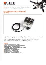
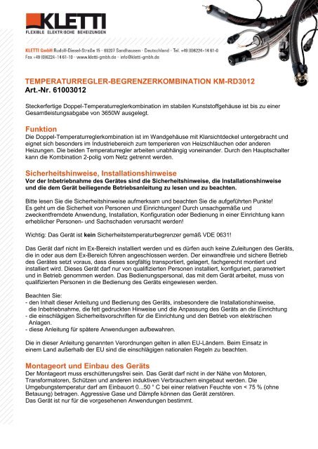
<strong>TEMPERATURREGLER</strong>-<strong>BEGRENZERKOMBINATION</strong> KM-RD3012<br />
Art.-Nr. 61003012<br />
Steckerfertige Doppel-Temperaturreglerkombination im stabilen Kunststoffgehäuse ist bis zu einer<br />
Gesamtleistungsabgabe von 3650W ausgelegt.<br />
Funktion<br />
Die Doppel-Temperaturreglerkombination ist im Wandgehäuse mit Klarsichtdeckel untergebracht und<br />
eignet sich besonders im Industriebereich zum temperieren von Heizschläuchen oder anderen<br />
Heizungen. Die beiden Temperaturregler arbeiten unabhängig voneinander. Durch den Hauptschalter<br />
kann die Kombination 2-polig vom Netz getrennt werden.<br />
Sicherheitshinweise, Installationshinweise<br />
Vor der Inbetriebnahme des Gerätes sind die Sicherheitshinweise, die Installationshinweise<br />
und die dem Gerät beiliegende Betriebsanleitung zu lesen und zu beachten.<br />
Bitte lesen Sie die Sicherheitshinweise aufmerksam und beachten Sie die aufgeführten Punkte!<br />
Es geht um die Sicherheit von Personen und Einrichtungen! Durch unsachgemäße und<br />
zweckentfremdete Anwendung, Installation, Konfiguration oder Bedienung in einer Einrichtung kann<br />
erheblicher Personen- und Sachschaden verursacht werden!<br />
Wichtig: Das Gerät ist kein Sicherheitstemperaturbegrenzer gemäß VDE 0631!<br />
Das Gerät darf nicht im Ex-Bereich installiert werden und es dürfen auch keine Zuleitungen des Geräts,<br />
die in oder aus dem Ex-Bereich führen angeschlossen werden. Der einwandfreie und sichere Betrieb<br />
des Gerätes setzt voraus, dass dieses sorgfältig transportiert, gelagert, fachgerecht montiert und<br />
installiert wird. Dieses Gerät darf nur von qualifizierten Personen installiert, konfiguriert, parametriert<br />
und in Betrieb genommen werden. Das Bedienungspersonal, das mit dem Gerät arbeitet, muss von<br />
qualifizierten Personen in die Bedienung des Geräts eingewiesen werden.<br />
Beachten Sie:<br />
- den Inhalt dieser Anleitung und Bedienung des Geräts, insbesondere die Installationshinweise,<br />
die Inbetriebnahme, die fett gedruckten Hinweise und die Anpassung des Geräts an die Einrichtung<br />
- die einschlägigen Sicherheitsvorschriften für die Einrichtung und den Betrieb von elektrischen<br />
Anlagen.<br />
- diese Anleitung für spätere Anwendungen aufbewahren.<br />
Die in dieser Anleitung genannten Verordnungen gelten in allen EU-Ländern. Beim Einsatz in<br />
einem Land außerhalb der EU sind die einschlägigen nationalen Regeln zu beachten.<br />
Montageort und Einbau des Geräts<br />
Der Montageort muss erschütterungsfrei sein. Das Gerät darf nicht in der Nähe von Motoren,<br />
Transformatoren, Schützen und anderen induktiven Verbrauchern eingebaut werden. Die<br />
Umgebungstemperatur darf am Einbauort 0...50 ° C bei einer relativen Feuchte von < 75 % (ohne<br />
Betauung) betragen. Aggressive Gase und Dämpfe können das Gerät zerstören.<br />
Das Gerät ist nur für die vorgesehenen Anwendungen bestimmt.
Abstimmung auf den Fühlertyp<br />
Vor jeder Inbetriebnahme des Geräts ist die Eingangsart für den Messeingang zu überprüfen.<br />
Es ist sicherzustellen, dass der für den vorgesehenen Betrieb bestimmte Fühlertyp korrekt an das<br />
Gerät angeschlossen ist.<br />
Installationshinweise<br />
Bitte lesen Sie die Installationshinweise aufmerksam und beachten Sie sämtliche aufgeführten<br />
Punkte bei der Installation des Geräts. Bei Missachtung dieser Installationshinweise kann es zu<br />
Funktionsstörungen kommen, oder es werden unter Umständen die geforderten EMV-Richtlinien<br />
nicht eingehalten, und es ist keine CE-Konformität mehr gegeben.<br />
Vergewissern Sie sich vor dem Anschluss und der Inbetriebnahme des Geräts, dass die Betriebs-<br />
spannung und die geforderten Betriebsspannungsverhältnisse des Geräts mit denen vor Ort<br />
übereinstimmen (siehe Typenschild und technische Daten). Treffen Sie wenn nötig entsprechende<br />
Maßnahmen.<br />
Vergewissern Sie sich, dass die Steuer- und Lastspannung vor Ort abgeschaltet und gegen<br />
Wiedereinschalten gesichert ist, während Sie das Gerät installieren. Die elektrischen Anschlüsse<br />
sind entsprechend dem Anschlussplan und den einschlägigen, nationalen Vorschriften vorzunehmen.<br />
Verlegen Sie die Zuleitungen zum Gerät so, dass sie unter allen Bedingungen frei<br />
von Zugbelastungen sind und unter keinen Umständen abscher- oder quetschgefährdet sind.<br />
Für die Fühlerleitungen und für die Signalleitungen sollten möglichst abgeschirmte Kabel ver-<br />
wendet werden, für Thermoelemente abgeschirmte Ausgleichsleitungen. Die Fühlerleitungen<br />
und die Signalleitungen müssen räumlich getrennt von Last- und Steuerleitungen (Starkstrom-<br />
leitungen) verlegt werden.<br />
Vom Gerät geschaltete induktive Verbraucher wie Schütze, Ventile, Motoren, Transformatoren<br />
etc. sowie im selben Schaltschrank bzw. in der selben Anlage installierte induktive Verbraucher<br />
sind mit gerätespezifischen Entstörmitteln zu entstören! Die Last- und Steuerkreise der Relais<br />
des Geräts müssen gegen Überstrom abgesichert werden.<br />
Das Gerät ist an einer separaten Netzzuleitung zu betreiben.<br />
Diese Anleitung enthält nicht alle Hinweise auf zu beachtende Vorschriften, Normen etc.,<br />
die beim Arbeiten mit dem Gerät in Verbindung mit Anlagen zu beachten und zu befolgen<br />
sind. Diese Vorschriften, Normen etc. sind vom Betreiber des Geräts anwendungsspezifisch zusammen<br />
zu stellen und zu beachten.<br />
Inbetriebnahme/Anschluß:<br />
Vor Inbetriebnahme der Temperaturregler-Begrenzerkombination muß folgendes beachtet werden:<br />
- Stimmen die Typenschildangaben mit Ihren Bestelldaten überein.<br />
- Die Netzspannung muß mit der Spannungsangabe auf dem Typenschild übereinstimmen.<br />
- Die Nennleistung des angeschlossenen Verbrauchers darf die Leistungsangabe auf dem Typenschild nicht<br />
überschreiten (ohmsche Last).<br />
- Es ist eine Schutzvorrichtung vorzusehen, die die Leitung bei Überlast vor zu hoher Temperatur schützt. Der<br />
Leitungsschutz nach VDE 0721 Teil 1, §19, muß gewährleisten, daß der Nennwert der Sicherung dem jeweiligen<br />
Verbraucher angepaßt wird und muß vor die Temperaturregler-Begrenzerkombination in Reihe geschaltet werden.<br />
Max. darf aber nur mit 16A abgesichert werden. Empfohlen wird ein Leitungsquerschnitt von mind. 1,5mm²<br />
- Haupt-Schalter auf Frontseite auf „0“ stellen.<br />
- Schukostecker in eine Schukosteckdose stecken<br />
- Die Heizung mit Ihrem Mehrpolstecker in die Mehrpolsteckdose stecken.<br />
Seite 2
Anpassung<br />
Das Gerät wird mit der in der Betriebsanleitung beschriebenen Grundeinstellung vorkonfiguriert<br />
ausgeliefert. Der Betreiber muss das Gerät auf die Regelstrecke der Anlage, in der es zum Einsatz<br />
kommt, anpassen. Insbesondere muss bei der Inbetriebnahme der max. Sollwert definiert werden.<br />
Einschalten<br />
Überprüfen Sie die Verdrahtung noch einmal sorgfältig! Eine falsche Verdrahtung des Geräts<br />
kann zu schweren Schäden an Gerät und Anlage führen! Achten Sie darauf, dass beim ersten<br />
Einschalten des Geräts die in einem unkritischen Betriebszustand ist, da das Gerät noch nicht<br />
auf die Anlage angepaßt ist und unter Umständen Fehlfunktionen auslösen kann.<br />
Haupt-Schalter einschalten – Grüne Signalleuchte im Schalter erstrahlt und LED-Display des Reglers und<br />
des Begrenzers gehen an.<br />
Die Alarmleuchte des Temperaturbegrenzers leuchtet. Sie leuchtet immer nach einem Netzausfall, einer<br />
Neueinschaltung oder wenn der Begrenzer ausgelöst hat.<br />
Einstellen<br />
Laut der nachstehenden Bedienung des Reglers und des Begrenzers, zuerst die Regelsollwerttemperatur<br />
einstellen, dann die Begrenzersollwerttemperatur. Die Begrenzersollwerttemperatur sollte möglichst<br />
immer mind. 20K höher sein als die Regelsollwerttemperatur.<br />
Danach muß im Parameter ^SN, der passende Fühlertyp zum eingesetzten Fühler angeglichen werden.<br />
Bei bedarf können Sie noch mehr Parameter ändern.<br />
Ist dies alles erledigt, und der Regler und der Begrenzer haben wieder die Soll-Ist-Anzeige, dann kann die<br />
Resettaste betätigt werden. Ist alles korrekt eingestellt gibt der Begrenzer den Regelausgang frei und die<br />
angeschlossene Heizung beginnt zu heizen. Durch das PID-Verhalten des Reglers schwingt die<br />
Isttemperatur beim ersten Hochheizen meistens deutlich über die eingestellte Solltemperatur.<br />
Ist nun die Begrenzersollwerttemperatur zu nah an der Isttemperatur des Reglers so löst der Begrenzer aus<br />
und schaltet die Heizung bleibend ab. Durch die Resettaste wird der Begrenzer entriegelt und gibt<br />
die Regelung wieder frei. Durch die Aktivierung der Selbstoptimierung beim Regler (Parameter AT)<br />
kann das Regelverhalten optimiert werden und somit auch das Überschwingen der Isttemperatur am Anfang.<br />
Beim Begrenzer sollten die Parameter möglichst nicht verändert werden.<br />
Nur erfahrenes Fachpersonal sollte eine Änderung der Parameter durchführen.<br />
Seite 3
Alarmausgang<br />
Der potentialfreie Alarmausgang kann zur Signalisierung in einer SPS oder Leitwarte herangezogen werden.<br />
Er signalisiert den Alarmfall wenn der Temperatur Begrenzer ausgelöst hat, d. h. wenn die Ist-Temperatur die<br />
eingestellte Solltemperatur am Temperatur Begrenzer überschritten bzw. erreicht hat.<br />
Der Alarmkontakt kann durch eine separate Kabelverschraubung im Klemmraum der Kombination auf Klemmen angeschlossen<br />
werden<br />
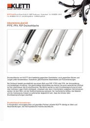
1. Namen und Funktionen der Teile:<br />
ST-48<br />
8.8.8.8.<br />
8.8.8.8.<br />
PV – Istwertanzeige<br />
SV – Sollwertanzeige<br />
ALM1 – Alarmwert 1<br />
ALM2 – Alarmwert 2<br />
A-M – Selbstoptimierung aktiv<br />
OUT – Relais Ausgang<br />
SET – Speichertaste<br />
(1) PV Fenster: zeigt die Ist-Temperatur (PV) rot beleuchtet an.<br />
(2) SV Fenster: zeigt die Soll-Temperatur (SV) grün beleuchtet an.<br />
Der Wert im SV-Fenster kann bei Tastennutzung eingestellt werden, z.B., Daten „Shift“ (Umschalten)<br />
Taste, „AB“ (Reduzieren) Taste und „AUF“ (Erhöhen) Taste.<br />
(3) ALM1 Anzeige: Wenn ALM1 Output an ist, die rote LED leuchtet auf.<br />
(4) ALM2 Anzeige: Wenn ALM2 Output an ist, die rote LED leuchtet auf.<br />
(5) A-M Anzeige: Wenn die Programmfunktion läuft, die grüne LED leuchtet auf.<br />
Gleichzeitige Blinken des A-M Indikators bedeutet, dass der aktueller Status läuft/hält.<br />
(6) OUT Anzeige: Wenn Ausgang “OUT” aktiv, dann leuchtet die grüne LED.<br />
(7) Modustaste (SET): Schaltet in den Einstellungsmodus um und registriert den Einstellungswert und den<br />
ausgewählte Wert. (Der Einstellungswert und der ausgewählte Wert werden durch das Drücken der<br />
Set-Taste registriert.)<br />
(8) SET-Taste ODER Programmfunktion Einstellungstaste ◄.<br />
Die ◄ Taste kombiniert mit der anderen Taste bestätigt alle Veränderungen.<br />
(9) Ab Taste (▼): Reduziert den numerischen Wert des Einstellungswertes.<br />
(10) Auf Taste (▲): Erhöht den numerischen Wert des Einstellungswertes.<br />
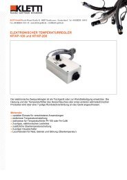
2. Display<br />
Nachdem Einschalten des Reglers erscheint folgende Anzeige im Display:<br />
1. Programmversion und eingestellter Fühler (ca. 2sec.)<br />
2. Danach wird in der oberen Anzeige der Istwert (rot; PV) angezeigt und in der unteren Anzeige der Sollwert<br />
(grün; SV).<br />
Power ON<br />
ST-48<br />
800.0<br />
800.5<br />
ST-48<br />
800.0<br />
A 60<br />
Sie können den Displaystatus � zum Displaystatus � ändern durch drücken der SET Taste. Dann wird der Output<br />
im unteren Displayfenster angezeigt. Status � und � ist der Basisstatus des Reglers (Siehe auch 2.1). Zwischen<br />
den zwei Basisstatus kann das SV Displayfenster den Systemstatus mit den nachfolgenden Signalen andeuten:<br />
"orAL", "outL", "ALM1", "ALM2", "Hy-1" oder " Hy-2".<br />
Seite 4<br />
ST-48<br />
800.0<br />
60
● Durch ein falsches Eingangssignal (verursacht durch falsche Sensorspezifikationen oder durch<br />
Kurzschluss), wird "orAL" blinkend angezeigt. Dann beendet der Regler seine Regelfunktion automatisch, und der<br />
Outputwert wird nach Parameter "outL" (0) gesetzt( Die Heizung wird unterbrochen).<br />
● Wenn der Alarm signalisiert wird, zeigt es "ALM1", "ALM2", "Hy-1" oder " Hy-2". Sie deuten die Max-Alarm,<br />
Min- Alarm, positive Abweichung und negative Abweichung der Alarme an.<br />
2.1 Basisfunktionen<br />
2.1.1 AUTO/Manuell<br />
Funktion muss in der Parameterebene (Parameter A-M) aktiviert sein. Durch drücken der SET-Taste kann<br />
zwischen Automatik und Manuell-Modus gewechselt werden. Wenn der Regler im Manuellmodus arbeitet, kann<br />
sein Outputwert prozentual durch das Drücken der ▲ und ▼ Tasten (unter Display-status �) erhöht oder<br />
reduziert werden.<br />
2.1.2 Parameterebene<br />
Drückt man die Set-Taste mehr als 3sec wechselt man in die Parameterebene (Parameter LOCK ist nicht<br />
aktiviert).<br />
Dann können die ▼\▲\◄ Tasten benutzt werden um die Parameter zu modifizieren. Durch das gleichzeitige<br />
Drücken der ◄ und SET Tasten verlässt man den Parametersetup. Der Regler kehrt automatisch in die<br />
Basisanzeige zurück, auch wenn keine Taste innerhalb von 30 Sekunden gedrückt wird.<br />
Notiz: Siehe Parametereinstellung LOOK 4.16 um den Parameterzugang zu sperren.<br />
Seite 5
Seite 6
3.0 Codes der Parameter-Einstellungen<br />
Code Beschreibung Einstellungsspektrum<br />
Einheit Bemerkungen<br />
ALM1 Hoch-Limit Alarm -1999~+9999 °C oder 1<br />
definierte Einheit<br />
ALM2 Tief-Limit Alarm -1999~+9999 °C oder 1<br />
definierte Einheit<br />
Hy-1 Positiver Ab- 0~9999 0.1°C oder 1<br />
weichungsalarm<br />
definierte Einheit<br />
Hy-2 Negativer Ab- 0~9999 1°C oder 1<br />
weichungsalarm<br />
definierte Einheit<br />
Hy Deadband 0~2000 Nur ON/OFFkontrolle<br />
u.<br />
Alarm<br />
At Kontrollmodus 0~3 Siehe nach<br />
Selbst-<br />
stehenden Text<br />
optimierung<br />
I Integralzeit 0~9999<br />
P Proportional-<br />
Bereich<br />
1~9999<br />
d Differentialzeit 0~2000 Sek.<br />
t Pausenzeit<br />
Ausgangsrelais<br />
0~120<br />
Sek.<br />
Sn Fühlerauswahl 0~21 Siehe nach<br />
stehenden Text<br />
dIP Dezimalstelle 0-3 0=0001°;<br />
1=000,1°<br />
P-SL Begrenzung<br />
unterer Sollwert<br />
-1999~9999<br />
P-SH Begrenzung<br />
oberer Sollwert<br />
-1999~9999<br />
Pb Istwertkorrektur -1999~1999 0.1°C oder 1<br />
definierte Einheit<br />
OP-A Outputmodus 0~3 Siehe nach<br />
Einstellung “0”<br />
stehenden Text<br />
nicht ändern<br />
outL Output Tief-Limit 0~110% 1% Nicht ändern<br />
outH Output HochLimit 0~110% 1% Nicht ändern<br />
Al-P Alarm Output 0~31<br />
Einstellung<br />
Definition<br />
„17“ nicht<br />
ändern<br />
CooL Definition: Heizen 0~7<br />
0 = Heizen<br />
Kühlen<br />
1 = Kühlen<br />
Addr Kommunikationsadresse<br />
0~63<br />
Nicht ändern<br />
bAud Baud Tempo 0~9600<br />
Nicht ändern<br />
FILT Digital Filter-input 0~20<br />
Digitalfilter<br />
definieren<br />
A-M A-M Status 0. Manuell<br />
1. Automatik/Manuell<br />
2. Automatik<br />
LocK Zugriffsparameter 0~9999 808 = uneingeschrängter<br />
EP1-EP8 Feldparameter<br />
Definition<br />
nonE-A-M<br />
4.0 Alarmparameter "ALM1", "ALM2", "Hy-1", " Hy-2”<br />
Seite 7<br />
Zugriff
Diese 4 Parameter stellen die Alarmfunktion des Reglers ein. Wird das Alarmsignal ALM1 ausgelöst, schließt das<br />
zusätzliche Alarmkontaktrelais (NC Kontakt). Optisch wird der Alarm durch die 2 Alarmleuchten ALM1 und ALM2<br />
signalisiert. So bald die Ursache für den Alarm entfernt wird, hört der Alarm automatisch auf.<br />
Alarmbedingungen:<br />
● ALM1: Absoluter Hoch-Limit Alarm. Wenn der Prozesswert größer ist als der "ALM1+Hy" Wert, ist der Alarm<br />
gesetzt. Er wird storniert, wenn der Prozesswert weniger ist als der "ALM1-Hy” Wert.<br />
● ALM2: Absoluter Tief-Limit Alarm. Wenn der Prozesswert größer ist als der "ALM2+Hy" Wert, ist der Alarm<br />
gesetzt. Er wird storniert, wenn der Prozesswert weniger ist als der "ALM2-Hy” Wert.<br />
ALM2 wird nicht auf das Alarmrelais geschaltet – nur optische Anzeige<br />
● Hy-1: Positiver Abweichungsalarm. Wenn PV minus SV größer ist als der "Hy-1+Hy" Wert, ist der Alarm<br />
gestellt. Es wird storniert, wenn der Prozesswert weniger ist als der "Hy-1-Hy". Wert. Es wird auch als zweiten<br />
Hoch-Limit Alarm benutzt bei On-Off Kontrolle.<br />
● Hy-2: Negativer Abweichungsalarm. Wenn PV minus SV größer ist als der "Hy-2+Hy" Wert, ist der Alarm<br />
gestellt. Es wird storniert, wenn der Prozesswert weniger ist als der "Hy-2+Hy" Wert. Es wird auch als zweiten<br />
Hoch-Limit Alarm benutzt bei On-Off Kontrolle.<br />
● orAL: Input über dem Bereich oder unter dem Bereich.<br />
Prozessvariabel übersteigt das konfigurierte Spektrum (Hoch-Limit oder Tief-Limit). Das wird von falscher<br />
Konfiguration des Sensortyps, von einem Sensorbruch oder Sensor-Kurzschluss verursacht. Das Ausgangsrelais<br />
fällt dann automatisch ab, bis die Ursache behoben ist.<br />
Unter anderem muss "orAL" nicht konfiguriert werden. Generell brauchen die Verbraucher all vier Alarme nicht.<br />
Die Limitwerte, die nicht benutzt werden können in den Parametern wie folgt eingestellt werden, um eine<br />
Alarmfunktion zu vermeiden.<br />
Beispiel:<br />
ALM1= 9999. ALM2 = -1999. Dann ist die Konfiguration Hy-1 = 9999 (999.9° C für Temperatur) oder Hy-2 =<br />
9999 (999.9° C für Temperatur) eingestellt. Wenn der Unterschied mehr als 9999 ist, werden die Hy-1 oder Hy-2<br />
Alarme nicht ausgelöst.<br />
4.1 Hystereseparameter "Hy"<br />
Der Hystereseparameter "Hy" kann als Schalt-Schutz bei hochfrequenten Störimpulsen im Stromnetz dienen. Der<br />
Hystereseparameter wirkt sowohl auf 4-Alarmkontrolle als auch auf das Auto-Tuning.<br />
Zum Beispiel: "Hy" Parameter kann den absoluter Hoch-Limit Alarm folgendermaßen beeinflussen. Es besorgt<br />
den Hoch-Limit Alarmparameter "ALM1" bei 800° C; "Hy" Parameter ist als 2.0° C eingestellt.<br />
● Der Kontroller ist am Anfang im normalen Status. Wenn der Prozesswert größer als 802° C ist (ALM1 +<br />
Hy), kann der absoluter Hoch-Limit Alarm ausgelöst werden.<br />
● Der Kontroller ist am Anfang im normalen Status. Wenn der Prozesswert größer als 798° C ist (ALM1 -<br />
Hy), kann der Alarm storniert werden.<br />
4.2 Parameter “At”<br />
At = 0, ON /OFF Regler, geeignet für einfache Regelaufgaben, oder wenn der Regler als Temperatur-Begrenzer<br />
eingesetzt wird.<br />
At = 1, Der läuft als PID-Regler mit und "Fuzzy" Kontrolle.<br />
At = 2, Gleiche Funktion wie vorher beschrieben. Mit zusätzlicher Auto-Tuning Aktivierung, d. h. der Regler wird<br />
automatisch auf die vorhandene Regelstrecke eingestellt um die bestmögliche Einstellung zu erlangen. Man sollte<br />
diese Einstellung beim Hochfahren der Heizung vornehmen. Angezeigt wird dieser Vorgang indem abwechselnd<br />
das Symbol „AT“ mit dem Sollwert im SV-Fenster angezeigt wird. Wenn die Einstellung abgeschlossen ist, wird<br />
"At" automatisch auf 3 gestellt .<br />
At = 3, diese Einstellung wird automatisch nachdem der Modus in AT=2 abgelaufen ist gestellt.<br />
Hier ist der Start des Auto-Tunings gesperrt, um die Widerholung der Funktion zu vermeiden.<br />
Sollte sich der Regelkreis ändern, wird empfohlen das Auto-Tuning zu wiederholen.<br />
4.3 Parameter “P”, “I”, “D”<br />
Der Proportional-Bereich , die Integralzeit und die Differentialzeit sind Regelbereichsspezifiche Einstellungen, die<br />
nur von geschultem Fachpersonal verändert werden sollten.<br />
4.4 PID Auto-Tuning dieses Reglers<br />
Seite 8
Um die bestmögliche Regleranpassung zu erzielen, sollte man über die Auto-Tuning Funktion die Regelstrecke<br />
automatisch anpassen lassen. Siehe dazu 4.2.<br />
4.5 Pausenzeit Ausgangsrelais "t"<br />
Der Parameter "t" kann zwischen 0 und 120 Sekunden eingestellt werden. Es stellt die Schalthäufigkeit des<br />
Ausgangsrelais und somit die Schaltgeschwindigkeit des Reglers dar. Die Schalthäufigkeit von<br />
10-20s hat sich als Praxiswert auch für nach geschaltete Leistungsrelais oder Schaltschütze bewährt,<br />
um die Lebensdauer der mech. Schaltkontakte nicht übermäßig zu reduzieren. Ist ein Solid-State-Relais<br />
nachgeschaltet, so kann der Wert auf < 5s minimiert werden.<br />
4.6 Fühlerauswahl “Sn”<br />
Bei diesem Regler kann man verschiedene Temperatur-Fühlerarten, wie Thermoelemente oder<br />
Widerstandselemente (RTD) einstellen. Durch eine automatische, nicht-lineare Kalibrierung der Thermoelemente<br />
und RTD ist der Eingangsfehler auf weniger als 0.2% reduziert. Die folgende Tabelle zeigt die Thermoelemente<br />
und RTD´s mit ihren dazugehörigen Auswahlziffern an.<br />
Sn Input Spez. Sn Input Spez.<br />
0 K 5 J<br />
1 S 20 Cu50<br />
4 E 21 Pt100<br />
4.7 Dezimalstelle Parameter "dIP"<br />
Dieser Parameter dient zur Einstellung der Anzeige mit einer Dezimalstelle, wenn der Mess-Regelbereich<br />
< 100°C ist.<br />
dIP = 0, ohne Dezimalstelle 0001°C.<br />
dIP = 1, mit Dezimalstelle 000.1°C.<br />
4.8 Untere und obere Eingabebegrenzung des Sollwertes: "P-SL" und "P-SH"<br />
Die untere und obere Eingabebegrenzung dient zur kontrollierten Begrenzung des Sollwertes bezogen auf den<br />
Prozess.<br />
Beispiel: Ein zu beheizendes Medium darf nur zwischen 20 und 100°C erwärmt werden – Einstellung<br />
„P-SL“ = 20 und „P-SH“ = 100 – so ist gewährleistet, dass der Sollwert nur in diesem Bereich geändert werden<br />
kann.<br />
4.9 Istwert Korrektur "Pb"<br />
Der Parameter "Pb" ist eine Istwertkorrektur, um Sensor/Inputsignal Fehler zu kompensieren.<br />
Z.B. kann man das Thermoelementsignal korrigieren, wenn Kompensationsfehler an möglichen Verbindungsstellen<br />
auftreten.<br />
Der Regler produziert keine Istwert- Fehler, weil die Technologie der digitalen Kalibrierung im Regler eingesetzt<br />
wird. Die automatische Nullmodulations garantiert keine Nulldrift.<br />
Beispiel: Das vorgegebene Signal bleibt unverändert, wenn Parameter "Pb" auf 0.0°C eingestellt wird.<br />
Entspricht das Eingangssignal einer Temperatur von 500.0°C und der Parameter "Pb" ist auf 10.0°C eingestellt<br />
wird, wird die Temperaturanzeige des Reglers 510.0°C sein.<br />
Notiz: Die Regler sind alle vor Auslieferung kalibriert, die Werkseinstellung des Parameter "Pb" ist also<br />
null. Stellen Sie nur diesen Parameter ein, wenn eine Abeichung durch vorgeschaltete Bauelemente (z. B.<br />
Zenerbarrieren) , lange Zuleitungen (2-Leiter Pt100) oder verschiedene Leitungsarten bei Thermoelementen<br />
vorgeschaltet sind – Den Korrekturwert ist jeweils selbst zu ermitteln.<br />
4.10 Output Definitionsparameter "OP-A", "outL" und "outH"<br />
Parameter "OP-A" definiert den Modus des Hauptoutputsignals, und die Parameter "outL" und "outH" definieren<br />
die Output Tief- und Obergrenzwerte.<br />
Notiz: Dieser Parameter ist für eine hier nicht verwendete Reglervariante gedacht um das Analog-<br />
Outputsignal einzustellen – bitte Einstellungen nicht ändern.<br />
4.11 Alarm Output Definitionsparameter "AL-P"<br />
● Einstellung "AL-P" = 17 bitte nicht ändern !!!<br />
"ALM1" ist Hoch-Limit Alarm<br />
Seite 9
"ALM2" ist Tief-Limit Alarm<br />
"Hy-1" ist Positiver Abweichungsalarm<br />
"Hy-2" ist Negativer Abweichungsalarm<br />
4.12 Funktionsparameter "CooL"<br />
Der Parameter "CooL" wird verwendet, um den Regler als Heiz- oder Kühlregler zu verwenden.<br />
● CooL = 0, Heizmodus für Heizprozesse.<br />
● CooL = 1, Kühlmodus für Kühlprozesse<br />
.<br />
4.13 Kommunikationsinterface Parameter “Addr” und "bAud"<br />
Notiz: Dieser Parameter ist für eine hier nicht verwendete Reglervariante gedacht um die möglichen<br />
RS232C oder RS4S5 Kommunikationsinterface als Zusatzfunktion zu installieren – bitte Einstellungen nicht<br />
ändern.<br />
.<br />
4.14 Input Digitalfilterparameter "FILT"<br />
Wenn das Eingangssignal auf Grund von externen Störungen stark beeinträchtigt wird, kann der Digitalfilter<br />
verwendet werden. Parameter "FILT" kann von 0 bis auf 20 konfiguriert werden.<br />
Filtereinstellung = 0 kein Filter aktiv<br />
Filtereinstellung = 2-5 bei kleinen Störungen<br />
Filtereinstellung = 6-20 bei größeren Störungen<br />
Grundsätzlich sollten die Störungen extern minimiert bzw. gar nicht erst auftreten.<br />
Der Filter sollte nur verwendet werden, wenn keine andere Möglichkeit besteht, die Störungen zu beseitigen.<br />
4.15 Systemparameter "A-M"<br />
Mit dem Parameter "A-M" kann der Regler nur Leistungssteller oder als Regler eingestellt.<br />
●A-M = 0 Manuell (Nur Leitungssteller)<br />
●A-M = 1 Automatik/Manuell Umschaltung mittels der ◄ Taste<br />
●A-M = 2 Automatik (PID-Regler)<br />
4.16 Zugangsbeschränkung Parametereinstellung "LocK"<br />
Wenn der Parameter "LocK" auf 808 eingestellt wird, können alle Parameter frei ohne Zugangsbeschränkung<br />
geändert werden. Bei anderen Einstellungen von „Lock“, kann man nur die Feldparameter 0~8 (EP1~EP8) und den<br />
LocK Parameter selbst ändern.<br />
● LocK = 0, erlaubt die Modifizierung der eingestellten Feldparameter, und den Sollwert.<br />
● LocK = 1, erlaubt das Ändern des Sollwerts im Display aber nicht die Änderung der ausgewählten Parameter.<br />
(außer Parameter LocK selbst)<br />
● LocK = 2, erlaubt nur die Ansicht des Sollwertes und der ausgesuchten Feldparameter (außer Parameter<br />
LocK selbst)<br />
● LocK = 808, erlaubt den ungehinderten Zugang zu allen Parameter und den Sollwert.<br />
Der „LocK“-Parameter sollte nur auf die o.g. Werte eingestellt werden.<br />
4.17 Feldparameter Definitionen "EP1-EP8"<br />
EP1-EP8 definieren die Feldparameter 1-8 für den Gebrauch in der Parametertabelle. Ihre Werte sind Parameter<br />
(außer Parameter EP selbst) wie "ALM1", "ALM2", etc., wenn LocK auf 0, 1, 2 und so weiter eingestellt wird. Nur<br />
die Parameter oder Einstellungswerte definierter Programme können eingestellt werden. Andere Parameter<br />
können nicht eingestellt oder modifiziert werden. Diese Funktion kann die Parametermodifikation beschleunigen<br />
und gegen falsche Modifizierung wichtiger Parameter (wie Input- und Outputparameter) vorbeugen.<br />
Die Parameter EP1 bis zu EP8 können 8 Parameter definieren (oder keiner). Es ist deshalb notwendig nutzvolle<br />
Parameter von EP1 bis zu EP8 in logischer Abfolge zu definieren. Der erste unbenutzte Parameter wird als null<br />
definiert. Zum Beispiel, die zwei Parameter "ALM1" und "ALM2" müssen bei Feldbedienern modifiziert werden.<br />
Der Parameter EP kann als folgendes eingestellt werden:<br />
LocK = 0, EP1 = ALM1, EP2 = ALM2, EP3 = nonE<br />
Manchmal werden Feldparameter nicht gebraucht, nachdem der Regler eingestellt wurde. Der EP1 Parameter<br />
kann als nonE eingestellt werden.<br />
Wartung und Reparatur:<br />
Reparaturen dürfen nur im Werk durchgeführt werden!<br />
Das Gerät muß nach den gültigen Bestimmungen (VDE 0105 Teil 100: 2000-06; SEV etc.) zum Erstellen und Warten nur<br />
vom Fachpersonal überprüft werden.<br />
Seite 10
Prüffristen nach BGV A3 sind einzuhalten.<br />
Auswechseln der internen Sicherungen für den Elektronikeinsatz.<br />
Bei einem Defekt kann die entsprechende Sicherung vom Fachpersonal wie folgt getauscht werden:<br />
- Regler spannungsfrei setzen – Netz freischalten und gegen wiedereinschalten sichern.<br />
- Wenn der Reglereinschub nichts mehr anzeigt muß die interne Schmelzsicherung getauscht werden, indem der<br />
Klarsichtdeckel geöffnet werden muß, und mittels Schraubendrehers die Verschlußkappe des Sicherungshalters auf<br />
der Frontplatte aufgedreht wird.<br />
- Schmelzsicherung durch neue gleichen Wertes ersetzen (20x5; 1A flink).<br />
- Einbau in umgekehrter Reihenfolge .<br />
Tech. Daten:<br />
Nennspannung: 230V/50Hz<br />
Nennleistung: max. 3650Watt ohmsche Last,<br />
Schutzklasse: I<br />
Schutzart: IP 65<br />
Regelverhalten: PID Regelgenauigkeit 0,5%<br />
Fühlerbruchsicherung: ja<br />
Fühlerart: PT100 oder FeCu-Ni (J), NiCr-Ni (K) !!!Typenschild beachten!!!<br />
Fühleranschluß: Mehrpolsteckdose 10-pol<br />
Verbraucheranschluß: Mehrpolsteckdose 10-pol max. 16A ohmsche Last<br />
Netzanschluß: Zuleitung mit Schukostecker 1,5mm²<br />
Hauptschalter beleuchtet: 2-polig<br />
Gehäuse: Kunststoff PC; Farbe: Lichtgrau ähnl. RAL 7035<br />
Maße: 166x160x134mm (BxHxT)<br />
Betriebstemperatur: 0 - 50°C<br />
Schaltausgang: Relais 16A ohmsche Last<br />
Anzeige: LED-Display<br />
Anzeige Alarm: Signalleuchte<br />
EMV-Verträglichkeit nach EN 61326<br />
Elektr. Sicherheit nach DIN EN 60204, EN 61010, BGV A3<br />
<strong>Kletti</strong> <strong>GmbH</strong><br />
Rudolf-Diesel-Straße 15<br />
D-69207 Sandhausen<br />
Telefon: +49 (0)6224/1461-0, Fax: +49 (0)6224/146110<br />
Mail: info@kletti-gmbh.de; Internet: www.kletti-gmbh.de<br />
Seite 11
temperature controller-limiter combination KM-RD3012<br />
Art-No.: 61003012<br />
Connector finished temperature controller-limiter combination in the stable plastic housing is displayed to a total<br />
achievement duty of 3650W.<br />
Function:<br />
The temperature controller-limiter combination is accommodated in the wall housing with clear visibility cover and suits<br />
temper itself especially in the industry area to that by heating tubes or other heatings.<br />
The temperature controller and the limiter work independently from one another. The limiter supervises the temperature of<br />
the heating through a characteristic temperature sensor and turns exceed in the adjusted triggering temperature the<br />
heating remaining off.<br />
Can be separated the combination 2-pole from the network by the main switch.<br />
Security references, installation references<br />
Before the starting of the device, the security references are, to read and are to be noted the<br />
installations of references and the operating instructions enclosed the device.<br />
You read security references favor the security references attentively and note you the itemized points!<br />
It concerns the security of persons and arrangements! Can be caused considerable persons and property damage by<br />
improper use, installation, configuration or operation in an arrangement!<br />
Important! The device is no Security temperature limiter in accordance with VDE 0631!<br />
The device may not be installed in the Ex-area and may lead connected become it also no cable of the device, that in, or<br />
out of the Ex-area! The flawless and certain business of the device prefaces that this carefully transports, stored, correctly<br />
mounted and installed becomes. This device may only of qualified persons installed, configures, taken become<br />
parametriert and in operation. The operation personnel that works with the device must become on manner of qualified<br />
persons into the operation of the device.<br />
Note:<br />
- the pertinent security directions for the arrangement and the business of electric units.<br />
- Store this instructions for later uses. The<br />
ordinances named in this instructions count in all EU-countries. In the use in a country<br />
outside of the EU, the pertinent national rules are to be noted.<br />
Mounting place and installation of the device<br />
The mounting places must be shock free. The device may not be incorporated in the vicinity by motors, transformers,<br />
marksmen and other inductive consumers. The Environment temperature may amount to at the<br />
installation place 0...50 ° C in one relative humidity of
tension and the demanded operating voltage of the device with which on the spot agree (see types sign and technical<br />
data). Encounter if compel corresponding measures. Reassure yourself that the tax tension and load tension is<br />
disengaged on the spot and is secured against automatic switching while you install the device.<br />
The electric connections are to be undertaken corresponding to the connection plan and the<br />
pertinent, national directions. In devices not connector finished you use sheaths in wiring with flexible cable. You transfer<br />
the power cable to the device so that they are under all conditions freely of train loads and shear off under no<br />
circumstances or bruise danger.<br />
For the sensor directions and for the signal directions, cables should as shielded as possible relative will turn, for<br />
thermocouple shielded balance directions. The sensor directions and the signal directions must<br />
spatially separated transferred become by load directions and tax directions (power current directions). Consumers<br />
turned inductive by the device as well as marksmen, valves, motors, transformers etc. as well as in the same housing<br />
and/or in the same unit installed inductive consumers are with devices specific undisturb! The load circle and tax circles<br />
of the relays of the device must be protected against over current. The device is to be operated at a separate power<br />
cable. This instructions do not contain are all references to directions to be noted, standards etc. to note and to follow that<br />
in the working with the device in connection with units. These directions, standards etc. are to be placed and are to be<br />
noted of the operator of the device use specific together.<br />
Starting connection:<br />
Before starting of the temperature regulator, following must be noted:<br />
- voices the types sign statement with your Order datas unanimously.<br />
- The network tension must agree with the tension statement on the types sign.<br />
- The achievement statement may not exceed (ohmsche load) the switching power of the connected consumer on the<br />
types sign.<br />
- A protection device is to be planned it, that protects the direction in overload against to high temperature. The<br />
direction protection after VDE 0721 parts 1, must guarantee, adapted becomes and must be turned that the nominal<br />
values of the security the respective consumer before the temperature regulator in row. Max. may be protected<br />
however only with 16A. Is recommended a direction cross-section of mind. Place 1,5mm²<br />
- head-switch on front side on „0“.<br />
- Stick Schuko power connector into a Schuko power outlet.<br />
- Heating and temperature sensors with the connectors into the more pole outlet.<br />
Alarm exit<br />
The potential free alarm exit can be requisitioned to signaled in a SPS or something else. It signaled the alarm case if the<br />
temperature limiter released, i.e. if the actual temperature the adjusted set temperatur exceeded at the temperature limiter<br />
and/or reaches has. The alarm contact can be connected<br />
by a separate cable introduction in the clamp room of the combination on clamps.<br />
Seite 13
Adaptation<br />
The device is delivered with the basic outlook described in the operating instructions preconfigured. The operator must<br />
adapt the device on the rule stretch of the unit, in which it comes to the use. Especially must in the starting of that max.<br />
Set value defined become.<br />
Turning on<br />
Reviewing you the wiring once again carefully! An incorrect wiring of the device can lead to heavy damages at device and<br />
unit! Eighth you on that that in the first turning on of the device that in an undiscerning operating status is, because the<br />
device is adapted not yet on the unit and can release under circumstances false functions. Turn on head-switches – green<br />
signal lamp in the switch light and the LED-displays of the controller and the limiter goes on. The alarm lamp of the<br />
temperatur limiter illuminates. It illuminates always after a network loss, a new insertion or if the limiter released.<br />
Adjust<br />
Adjust loudly the following operation of the controller and the limiter, first set the temperature controller control setpoint,<br />
then set the temperature limiter control setpoint. The temperature limiter control setpoint should if possible always at least<br />
20K more highly its than the temperature controller control setpoint. After that must in the parameter SN, that are adjusted<br />
suitable sensor type to the used sensor. In can need you yet more parameter change. This is settled everything, and the<br />
controller and the limiter shows again the actual value and the set value, then can be actuated the reset push key. All<br />
correctly is adjusted gives the limiter the rule exit free and the connected heating begins to heat. Through the PIDbehavior<br />
of the controller, the temperature swings in the first highly heat usually clearly over the adjusted temperature<br />
control setpoint. The temperature limiter control setpoint is so releases now too closely at the temperature of the controller<br />
the limiter disengages the heating remaining. Through the reset push key, the limiter gives the controller free again. In the<br />
controller (parameters AT), the rule behavior can be optimized by the activation of the even optimization and therefore<br />
also the over swing of the its temperature at the beginning.. In the limiter parameters not if possible should be changed.<br />
Only learned specialist staff should carry out a change of the parameters.<br />
Seite 14
1.2 Name and function of the section:<br />
(1) PV display: Indicate the process variable (PV) with the red LED.<br />
PV window shows real time temperature measuring value .<br />
(2) SV display: Indicate the setting value (SV) or manipulated variable (MV) with the green LED.<br />
The value of SV windows can be adjusted by using the key like data shift key, decrease key,<br />
increase Key.<br />
(3) ALM1 indicator: When ALM1 output is ON, the red LED lights<br />
(4) ALM2 indicator: When ALM2 output is ON, the red LED lights<br />
(5) A-M indicator: The programming function is valid, the green LED lights.<br />
At the same time A-M indicator lights on/off means current status run/hold.<br />
(6) OUT indicator: When OUT is ON, the green LED lights<br />
(7) Mode key (SET): Switches the setting mode and registers the setting value and selected value<br />
respectively. (Setting value and selected value are registered by pressing the mode key.)<br />
(8) Data shift key OR programming function setting ◄ key<br />
When the ◄key combined with the other key can made data changing come true.<br />
(9) Decrease key (▼): Decrease numeric value of the setting value.<br />
(10) Increase Key (▲): Increase numeric value of the setting value.<br />
2.0 Display Status<br />
After power on, display status (1) will be shown: the upper display window displays four digital<br />
measured value (PV).The lower display window displays four-digit setting value (SV) and can<br />
set radix-point (or precision).<br />
You can change the display status (1) into the status (2) by pressing SET key, then output<br />
value will be displayed in the lower display window. The status (1) and (2) are the basal status of<br />
the controller. Between the basal status, SV display window can indicate some certain state of the<br />
system by some signals, such as "orAL", “outL” "ALM1", “ALM2” "Hy-1", or " Hy-2".<br />
- If the input signal value beyond the measurement range (caused by wrong setting of<br />
sensor spec. or open (short) circuit). "orAL" will be displayed with blinking Then the<br />
controller terminate its control function automatically, and the output value is fixed<br />
according to the parameter “outL:”<br />
Seite 15
- When alarm occurred, it will d isplay "ALM1", “ALM2” "Hy-1", or " Hy-2". They<br />
indicate the upper limit alarm, lower limit alarm, positive deviation alarm, and negative<br />
deviation alarm<br />
2.1 Basal operation description<br />
2.1.1 Display transfer<br />
Press SET key can change the display status. It can be transferred among the display<br />
status (1) and (2).<br />
2.1.2 Data setup<br />
If the parameter LOCK is void, we can setup most of the data displayed in SV display<br />
Window. For example, set radix point input of display precision as follows:<br />
To set SV value and radix point input must be under status (1) key to. Press ▼<br />
decrease the value, press ▲ key to increase the value, Press ◄ key to shift and<br />
set radix point, press once the point move one unit forward.<br />
When the point shift a certain digit you can change the number of the digit by pressing ▼\ ▲,<br />
in the end please press SET again to confirm the setting.<br />
2.1.3 Man/Auto mode switch<br />
Alternate switching between AUTO and MAN can be performed by pressing SET key<br />
once. If the controller is working on Manual mode, its output value can be increased or decreased<br />
by pressing ▲ and ▼ key under display status (2) .<br />
2.1.4 Setting parameters<br />
If the controller s hows basal display status (display status (1) or (2)), press SET and<br />
hold about 2 seconds until parameter is displayed (display status (3)).Then the key ▼ / ▲ / ◄<br />
be used to modify parameters. Press and hold the ◄ key can return to the<br />
preceding parameter. Press ◄ key (don’t release) and then press SET key<br />
simultaneously can escape from the parameter setup .The controller will escape<br />
automatically from the parameter setup operation if no key is pressed within 30 seconds.<br />
Note: refer to the controller whose parameters are locked by setting parameter “Lock”,<br />
Most of its parameters are inhabited except those defined by field parameter “EP”<br />
2.2 Artificial intelligence control and auto tuning<br />
So if you want to execute auto tuning, you must adjust set point to an often-used value first,<br />
and then press and hold the ◄ key for about 2 seconds until the "At" symbol is displayed in the<br />
lower display window if you want to start up auto tuning function (Auto tuning a not allowed to<br />
start up again unless you set parameter Ctrl to 2 manually if the function has been executed once).<br />
During auto tuning, the controller executes on-off control After 2-3 times on-off action, the<br />
microprocessor in the controller will analyze the period, amplitude, waveform of the oscillation<br />
generated by the on-off control, and calculate the optimal control parameter value. The controller<br />
begins to perform accurate artificial intelligence control after parameter auto tuning is finished If<br />
you want to escape from auto tuning status, press and hold ◄key for about 2 seconds until<br />
the blinking of “At” symbol is stopped in the lower display window. Generally it will meet your<br />
need to perform auto tuning one time only. After the auto tuning is finished, the controller will set<br />
parameter “At” to 3(factory set is 1), and now it is not allowed to start up auto tuning by pressing<br />
◄ key on front panel. This will avoid repeat auto tuning by mistake.<br />
Seite 16
Seite 17
Code setting mode<br />
Code description Setting range Engineer unit remarks<br />
ALM1 High limit alarm -1999 +9999 °C or defined unit Linear unit defined<br />
ALM2 Low limit alarm -1999 +9999 °C or defined unit by para P-SL and P-<br />
SH<br />
Hy-1 Positiv deviation<br />
0 - 9999 0,1°C or defined unit When linear voltage/<br />
alarm<br />
resistance<br />
Hy-2 Negativ deviation<br />
alarm<br />
0 - 9999 0,1°C or defined unit Input is selected<br />
Hy Dead band 0-2000 ON/OFF control and<br />
alarm only<br />
At Control mode 0-3<br />
See the text for<br />
details<br />
I Hold parameter 0-9999 0,1°C or defined unit 0 disable integral<br />
function<br />
P Rating parameter 1-9999<br />
d Lag time 0-20000 sec.<br />
t Control period/<br />
Output smooth<br />
0-125 sec.<br />
Sn Input spezification 0-21<br />
Configure varied<br />
See the text for detail<br />
resolution<br />
dIP Decimal point<br />
position<br />
0-3<br />
P-SL Input Low limit -1999 +1999<br />
P-SH Input High limit -1999 +1999<br />
pb Input shift -1999 +1999 0,1°C or defined unit<br />
OP-A Output mode 0-2<br />
See the text for detail<br />
outL Output Low limit 0-110% 1%<br />
outH Output High limit 0-110% 1%<br />
AL-P Alarm output<br />
0-31<br />
definition See the text for detail<br />
Cool System function<br />
0-7<br />
definition See the text for detail<br />
Addr Communication<br />
address<br />
0-63<br />
Baud Baud rate 0-9600<br />
FILT Digital filter output 0-20 Define digital filter<br />
intensity<br />
A-M A-M status 0 – Manual<br />
1 – automatic<br />
2 – automatic and<br />
suppress manual<br />
Lock Configureation<br />
privilege<br />
0-9999<br />
EP1- Filed parameter noneE-A-M<br />
EP8 definition<br />
Seite 18
4.1 Alarm parameter "ALM1", "AIM2", "Hy-1", " Hy-2”<br />
These 4 parameters set controller's alarm function. Alarm signal will be triggered to make<br />
controller's relay contact close (NC contact open), if alarm condition is satisfied.<br />
Alarm message is displayed in turn in SV display window. When the cause of alarm is removed, then the alarm<br />
is cleared automatically.<br />
Alarm condition is following:<br />
- ALM1: Up limit absolute alarm. If the process value is greater than the value specified as<br />
"ALM1+Hy” then the alarm is set, and the alarm will be cancelled if the process value is less than<br />
the value of “ALM1-Hy”.<br />
- ALM2: Low limit absolute alarm. If the process value is greater than the value specified<br />
as "ALM2+Hy”, then the alarm is set, and the alarm will be cancelled if the process value is less<br />
than the value of “ALM2-Hy”.<br />
Hy-1: Positive alarm. If PV minus SV is greater than the value specified as " Hy-1+Hy”<br />
the alarm is set, and the alarm will be cancelled if the process value is less than the value of<br />
“Hy-1-Hy ". It also used as the second high limit alarm in case of on-off control.<br />
Hy-2: Negative deviation alarm. If PV minus SV is greater than the value specified as<br />
"Hy-2 +Hy ", the alarm is set, and the alarm will be cancelled if the process value is less than the value of<br />
“Hy-2+Hy”. It also used as the second high limit alarm in case of on-off control.<br />
- orAL -Input over range or under range<br />
Process variable exceeds the configured range (High limit or low limit), caused by error<br />
configuration of sensor type, sensor disconnection or short-circuit. In the event of input over range,<br />
controller will stop control automatically and the value specified in advance as the parameter<br />
"outL”~ is Output as the manipulated value.<br />
Among which "orAL" don't need to be configured. Generally users don't need the whole 4<br />
alarms. Limit value can be set to those parameters not used to avoid alarm function. Ex, the<br />
following configuration:<br />
ALM1=9999. ALM2=-1999. When the configuration Hy-1=9999 (999.9 for temperature)<br />
or Hy-2 =9999 (999.9 for temperature) is set. Even if the difference value is<br />
greater than 9999, Hy-1 Hy-2 or alarm will not be triggered.<br />
4.2 Dead band parameter "Hy"<br />
Dead band parameter "Hy" is set to permits protection of position control output from<br />
high switching frequencies caused by process input fluctuation. Dead band parameter is used for<br />
position control. 4-alarm control as well as the position control at auto tuning.<br />
For example: " Hy " parameter can affect upper absolute alarm as the following, provided<br />
upper alarm parameter " ALM1” is set as 800"C, "Hy" parameter is set as 2.0°C<br />
- Controller is in normal status at the beginning. When the process value is greater than<br />
802°C (ALM1 + Hy), the upper absolute alarm can be triggered.<br />
- controller is in normal status at the beginning. When the process value is less than 798°C<br />
(ALM1-Hy ), the alarm can be canceled.<br />
4.3 Control mode parameter “At”<br />
At =0 ON /OFF control, suitable for the occasions which don't need high precision.<br />
At =1 It is improved on the basis of PID control and fuzzy control, having more extensive<br />
adaptabilities with the process, and this can get a good control to processes .Under<br />
the situation, ”At” function can work by setting the panel.<br />
At =2 Auto-tuning function is enabled. (points for attention have been described in<br />
preceding text.) When completing the setting, “At” is set to 3 automatically.<br />
At =3 Artificial-intelligence adjusting. The state is automatically set after auto-tuning<br />
completting. On this setting, start-up of auto- tuning from the front panel is inhibited<br />
to prevent the same function again.<br />
Seite 19
4.4. Control action explanations<br />
4.4.1 PID<br />
(1) Proportional band "p"<br />
Proportional action is the action which the control output varies in proportion to the<br />
deviation between the setting value and the processing temperature<br />
If the proportional band is narrowed, even if the output changes by a slight variation of the<br />
processing temperature, better control results can be obtained as the offset decreases.<br />
However, if the proportional band is narrowed too much, even slight disturbances may<br />
cause variation in the processing temperature, control action changes to ON/OFF action and the so called<br />
hunting phenomenon occurs.<br />
Therefore, when the processing temperature comes to the balanced position near the<br />
setting value and a constant temperature is maintained, the most suitable value is selected by<br />
gradually narrowing the proportional band while observing the control results.<br />
(2) Integral time "I”<br />
Integral action is used to eliminate offset When the integral time is shortened, the returning<br />
speed to the setting point is accelerated However, the cycle of oscillation is also accelerated and<br />
the control becomes unstable.<br />
(3) Derivative time “D”<br />
Derivative action is used to restore the change in the processing temperature according to<br />
the rate of change. It reduces the amplitude of overshoot and undershoot width .<br />
If the derivative time is shortened, restoring value becomes small, and if the derivative<br />
time is made longer, an excessive returning phenomenon may occur and the control system may<br />
be oscillated<br />
4.4.2 PID auto-turning of this controller<br />
In order to decide each value of P, I. D and ARW automatically, this system forcibly<br />
fluctuates the object being controlled.<br />
Seite 20
4.4.3 Auto reset (offset correction)<br />
Auto-reset is performed to correct the offset at the point at which PV indication is stabilized<br />
within the proportional band during the PD action<br />
Since the corrected value is internally memorized. It is not necessary to perform the<br />
auto-reset again as long as the process is the same.<br />
However, when the proportional band is set to 0 the corrected value is cleared.<br />
Seite 21
4.5 Output period "t"<br />
Parameter "t" can be set between 0.5 to 125 seconds. It represent the calculate speed of the<br />
controller When t increased, proportion function will be increased and derivative function<br />
will be derivative function is absolutely eliminated, then the system is a proportional decreased.<br />
If t > =5s, or proportional-integral system The change of this parameter will nearly have no<br />
influence to the system if t is less than 1/5 of its original value.<br />
The following principle is for adjusting parameter "t"<br />
- In case of time proportional output mode, if SSR (Solid state relay) or PBR is used as<br />
executive bodies, then control period can be set smaller (generally 0.5 through 2 seconds) to<br />
improve control precision. If relay contact output is used, then parameter "t" should be set<br />
to be larger than or equal 4 seconds generally, because a small value set will decrease<br />
service life of mechanical contacts. A large value set will increase service life of relay, but<br />
will decrease control precision, so select a value to satisfy both sides.<br />
- In case of liner current output, decreasing parameter "t" will speed up output<br />
responsibility and improve control precision, but will lead to frequently changed output<br />
current and arising there from frequent movement of executive bodies (ex. Control value).<br />
Now increasing parameter "t" appropriately will make value move smoothly.<br />
4.6 Input specification parameter “Sn”<br />
The controller is available with varied input function. Different input type such as<br />
thermocouple and RTD can be selected in the same controller through parameter setting.<br />
Automatic non-linear calibration of high precision for thermocouple and RTD is available in the<br />
controller, with measurement input accuracy less than 0.2%F.S. The following table shows input<br />
pecification corresponding to the set value of parameter Sn .<br />
SN Input spec. SN Input spec.<br />
0 K 5 J<br />
1 S 20 CU50<br />
4 E 21 Pt100<br />
4.7 Decimal point setting parameter "dIP"<br />
In case of thermocouple or RTD input, dIP is used to define temperature display resolution.<br />
dIP=0 , temperature display resolution is 1 .<br />
dIP=1 , temperature display resolution is 0.1 .<br />
Adjustment of this parameter only affects the display, and gives no effect on control or<br />
retransmission output because the internal temperature measurement resolution is fixed at 0.1 ,<br />
then temperature will be display at resolution of 0.1 : for input below 1000 and 1 for input<br />
over 1000<br />
4.8 “P-SL” and "P-SH": Scale definition parameter for linear<br />
input/retransmission output<br />
Parameter "P-SL" and "P-SH" are used to define the display span for linear input, and to set<br />
the engineering unit for measurement. In case of thermocouple or RTD input Parameter "P-SL"<br />
and "P-SH" are not used.<br />
Seite 22
4.9 Input shift parameter "Pb"<br />
Parameter “Pb” is used to make input shift to compensate the error produced by sensor or<br />
input signal itself.<br />
For thermocouple input, parameter "Pb" is used to correct reference junction compensation<br />
error.<br />
The controller itself will not produce error after a long lime used, because the technology of<br />
digital calibration is used in the controller to substitute potentiometer of bad stability,<br />
and function of automatic zero modulation will guarantee no zero drift produced in the controller .<br />
Parameter "Pb " is used to make input shift to compensate the error produced by<br />
measurement. For example, provided input signal keep unchanged, if when parameter " Pb "<br />
is set to 0.0°C the temperature measurement of the controller is 500.0°C, then when parameter<br />
"Pb" is set to 10.0°C the temperature measurement display will be 510.0°C.<br />
Note: controller are all calibrated before delivering, and so the default value of<br />
Parameter "Pb" is zero. Only adjust this parameter when recalibration of measurement<br />
is necessary.<br />
4.10 Output definition parameter "OP-A", "outL" and "outH"<br />
Parameter “OP-A” is used to define the mode of main output signal, and parameter “outL”<br />
and “outH” is used to define output lower limit and upper limit.<br />
Note: setting of parameter " OP-A" must conform to the module type installed as<br />
main output.<br />
- OP-A =0, the mode of main output is time-proportional output of on-off mode (for<br />
on-off control).<br />
If output modules such as SSR voltage output, relay contact discrete output, BCR cross<br />
zero trigger output and BCR n0-contact discrete output are installed as main output, then<br />
“OP-A = 0" should set.<br />
- OP-A = 1, any specification DC current output, continuous output mode. Linear current<br />
output module should be installed to main output.<br />
- OP-A = 2, actuation is time proportional output of on-off mode.<br />
- outL, restrain minimum value of adjust output. When the function of sectional power<br />
restriction is executed, it’s the output upper limit if output value is lower than the value of<br />
lower limit alarm If bi-directional adjustment software is installed, then controller is<br />
turned to be duo directional output system, when outL
4.12 Fanction parameter "CooL"<br />
Parameter “CooL” is used to select some system functions<br />
- CooL =0, reverse action control mode. When this mode is selected, an increase in PV<br />
results in decrease in control output .Ex, heating control.<br />
- CooL=1, direct action control mode. When this mode is selected, an increase in PV<br />
results an increase in the control output, Ex. cooling control.<br />
4.13 Communication interface related parameters “Addr” and "bAud"<br />
When RS232C or RS4S5 communication interface is installed as auxiliary function,<br />
parameter "Addr" and "bAud" is used to define the communication address and baud rate define<br />
respectively for communication modules in the controller.<br />
4.14 Input digital filter parameter "FILT"<br />
If input fluctuates engender due noise, then digital filter can be used to smooth the input.<br />
Parameter "FILT" may be configured in the range of 0 to 20, among which, 0 means no filter,<br />
1 means intermediate-value filter and 2-20 means that intermediate-value filter and second order<br />
integral filter can be selected simultaneously.<br />
The multiples of second filter is the square parameter "FILT", and can be up to hundreds<br />
times. When a large value is set, the measurement input is stabilized but the responsibility at the<br />
time is deteriorated. Generally if great interference exists, then you can increase parameter<br />
“FILT” gradually to make momentary fluctuation of measurement input less than 2 to 5 values.<br />
If the controller is being tested at laboratory, then parameter "FILT" should be sit to 0 or 1 to<br />
shorten the time responsibility.<br />
4.15 System parameter "A-M"<br />
Parameter “A-M” is used to define Auto /Manual status, as below:<br />
A-M =0 Manual control mode<br />
A-M =1 control mode<br />
A-M =2 Automatic control state ,in this state manual operation is prohibited.<br />
4.16 Privilege for parameter set "Lock"<br />
When parameter “LocK” is set as 808, you can set all the parameters, while LocK is set the<br />
other value ,then you only can set 0~8(EP1~EP8) field parameter and Lock value itself.<br />
Parameter LocK provides several operation privileges, as following:<br />
- Lock=0, allowed to modify field parameters, and set point is allowed.<br />
- Lock=1, allowed to display and view field parameters, and to set point . But the<br />
modification of field parameters (except parameter Lock itself) is allowed.<br />
- Lock=2, allowed to display and view field parameters, and to set point . But the<br />
modification of field parameters (except parameter Lock itself) is not allowed.<br />
- Lock=808, allowed to set all parameters.<br />
If Lock is set to other values than the above mentioned, the result may be one of those<br />
above mentioned, and most of them are the same as when Lock=1 is set.<br />
If you set LocK to be 808 during field parameter (EPI-EP8) setting, parameter Lock will<br />
automatically turned to be 0 when you finished setting field parameter, but if you set Lock to be<br />
808 after the parameters are unlocked, parameter LocK will be saved as 808 permanently.<br />
Seite 24
.<br />
4.17 Field parameter definition: "EP1-EP8"<br />
EPI-EP8 define 1-8 field parameters for operators use in parameter table. Their parameter<br />
values are parameters except parameter EP itself like "ALM1", "ALM2", etc. when LocK is set to<br />
0,1,2, and so on. Only parameters or setting values of program defined can be displayed, other<br />
parameters can not be displayed and modified. This function can speed up the parameter<br />
modification and prevent important parameters (like input, output parameters) from modifying<br />
falsely.<br />
Parameters from EPI to EP8 can define 8 field parameters at most, if the number of field<br />
parameters is less than 8 (sometimes even none), it is necessary to define useful parameters from<br />
EP1 to EP8 in order, the first (parameter which are not used is defined as none. For example, two<br />
parameters of "ALM1" and "ALM2" need to be modified by field operators, the parameter EP can<br />
be set as following:<br />
Lock=0, EP1=ALM1, EP2=ALM2, EP3=nonE.<br />
Sometimes field parameters are not needed after we finish adjusting the controller, we can<br />
set EP1 parameter as nonE.<br />
5.00 Additional remarks of Time proportional output (when OP-A=0)<br />
In case of time proportional output mode, the output value can change by adjusting, during<br />
a fixed base period, the ratio of relay on-off time (or the ratio of the time during which SSR high<br />
voltage output or low voltage output is activated).<br />
Time proportional output can be regarded as a square wave, the base period of which<br />
equals to control period "T", and the output value of which direct proportional to the on-off ratio<br />
of the square wave. The on-off ratio may be configured to be in the range of 0% to 100%. For<br />
special applications, the range of time proportional output can be clamped by tuning parameters<br />
"outL" and “outH”. Fox example, if the output need to be clamped to between 20% and 60%,<br />
then "outL=20, outH=60" may just be set. Normally in case of time proportional output, if<br />
"outL=0, outH=100" is set, there will be no output limit.<br />
Below is a schematic diagram for time proportional output (waveform respectively for<br />
output being 40% and 60%)<br />
6.00 Further description about general work mode<br />
6.1 ON-OFF control (simple temperature controller)<br />
Dead band of ON-OFF control can be set by parameter “Hy”. When controller are used for<br />
ON-OFF control, it should be set as below: t=0. OP-A=0<br />
Parameter for artificial intelligence control, such as P, I, D and T, have no function in this occasion.<br />
LocK=l : inhibit the modification of field parameters, and the display and modification of<br />
other parameters.<br />
EP1=nonE: field parameters are not defined.<br />
6.20 3-point (upper, lower alarm) control<br />
To make the controller have upper, lower alarm function, the parameters should be set as below:<br />
At=0, OP-A=2, COOL=0, AL-P=l7, LocK=0, EP1=ALM1, EP2=none<br />
Seite 25
Maintenance and repair:<br />
Repairs may be carried out only in the work! The device must be reviewed after the valid determinations (VDE<br />
0105 parts 100: 2000-06; SEV etc.) for generation and maintenance men only by the specialist staff. Test time<br />
periods after BGV A3 are to be kept.<br />
Exchanging of the internal securities for the electronics use and the Schuko power outlet.<br />
In one defective the corresponding security of the specialist staff can follow traded become how.<br />
- combination tension free set – disconnect network and against switching of certain.<br />
- If the displays shows nothing more must indicate the internal enamel security traded become in that the<br />
clear visibility cover must be opened, and by means of srewdriver the fastener cap the security holder is turn<br />
up on the front disk.<br />
- Replace enamel security by new same value (rule pure push 1x 20x5mm, 1A agilely).<br />
- Installation in reversed sequence.<br />
Technical Data:<br />
Operating voltage: 230V/50Hz<br />
Switching power: max. 3650Watt ohmsche load<br />
Electrical protection class: I<br />
protection type: IP 65<br />
rule behavior: PID; contrller- accuracy 0,5%<br />
sensor breach security: yes<br />
sensor type: PT100 oder FeCu-Ni (J), NiCr-Ni (K) !!!types sign!!!<br />
sensor connection: 10 pole outlet<br />
consumer connection: 10 pole outlet 16A ohmsche load<br />
network connection: power cable with Schuko power connector 1,5mm²<br />
main switch illuminates: 2-pole<br />
housing:plastic ABS and PC<br />
masses: 160x166x134mm (BxHxT)<br />
Ambient temperature: 0 - 50°C<br />
scarf cable gear: relay 16A ohmsche load<br />
LED-display<br />
EMV-compatibility: EN 61326<br />
Safety instructions: DIN EN 60204, EN 61010, BGV A3<br />
<strong>Kletti</strong> <strong>GmbH</strong><br />
Rudolf-Diesel-Straße 15<br />
D-69207 Sandhausen<br />
Telefon: +49 (0)6224/1461-0, Fax: +49 (0)6224/146110<br />
Mail: info@kletti-gmbh.de; Internet: www.kletti-gmbh.de<br />
Seite 26