an alternative proposal for the design of balanced cantilever bridges ...
an alternative proposal for the design of balanced cantilever bridges ...
an alternative proposal for the design of balanced cantilever bridges ...

Create successful ePaper yourself
Turn your PDF publications into a flip-book with our unique Google optimized e-Paper software.
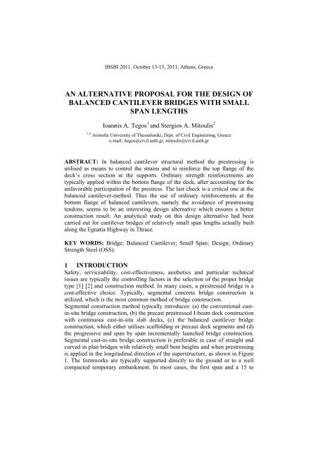
IBSBI 2011, October 13-15, 2011, A<strong>the</strong>ns, Greece<br />
AN ALTERNATIVE PROPOSAL FOR THE DESIGN OF<br />
BALANCED CANTILEVER BRIDGES WITH SMALL<br />
SPAN LENGTHS<br />
Io<strong>an</strong>nis A. Tegos 1 <strong>an</strong>d Stergios A. Mitoulis 2<br />
1,2 Aristotle University <strong>of</strong> Thessaloniki, Dept. <strong>of</strong> Civil Engineering, Greece<br />
e-mail: itegos@civil.auth.gr, mitoulis@civil.auth.gr<br />
ABSTRACT: In bal<strong>an</strong>ced c<strong>an</strong>tilever structural method <strong>the</strong> prestressing is<br />
utilised as me<strong>an</strong>s to control <strong>the</strong> strains <strong>an</strong>d to rein<strong>for</strong>ce <strong>the</strong> top fl<strong>an</strong>ge <strong>of</strong> <strong>the</strong><br />
deck’s cross section at <strong>the</strong> supports. Ordinary strength rein<strong>for</strong>cements are<br />
typically applied within <strong>the</strong> bottom fl<strong>an</strong>ge <strong>of</strong> <strong>the</strong> deck, after accounting <strong>for</strong> <strong>the</strong><br />
unfavorable participation <strong>of</strong> <strong>the</strong> prestress. The last check is a critical one at <strong>the</strong><br />
bal<strong>an</strong>ced c<strong>an</strong>tilever-method. Thus <strong>the</strong> use <strong>of</strong> ordinary rein<strong>for</strong>cements at <strong>the</strong><br />
bottom fl<strong>an</strong>ge <strong>of</strong> bal<strong>an</strong>ced c<strong>an</strong>tilevers, namely <strong>the</strong> avoid<strong>an</strong>ce <strong>of</strong> prestressing<br />
tendons, seems to be <strong>an</strong> interesting <strong>design</strong> <strong>alternative</strong> which ensures a better<br />
construction result. An <strong>an</strong>alytical study on this <strong>design</strong> <strong>alternative</strong> had been<br />
carried out <strong>for</strong> c<strong>an</strong>tilever <strong>bridges</strong> <strong>of</strong> relatively small sp<strong>an</strong> lengths actually built<br />
along <strong>the</strong> Egnatia Highway in Thrace.<br />
KEY WORDS: Bridge; Bal<strong>an</strong>ced C<strong>an</strong>tilever; Small Sp<strong>an</strong>; Design; Ordinary<br />
Strength Steel (OSS).<br />
1 INTRODUCTION<br />
Safety, serviceability, cost-effectiveness, aes<strong>the</strong>tics <strong>an</strong>d particular technical<br />
issues are typically <strong>the</strong> controlling factors in <strong>the</strong> selection <strong>of</strong> <strong>the</strong> proper bridge<br />
type [1] [2] <strong>an</strong>d construction method. In m<strong>an</strong>y cases, a prestressed bridge is a<br />
cost-effective choice. Typically, segmental concrete bridge construction is<br />
utilized, which is <strong>the</strong> most common method <strong>of</strong> bridge construction.<br />
Segmental construction method typically introduces: (a) <strong>the</strong> conventional castin-situ<br />
bridge construction, (b) <strong>the</strong> precast prestressed I-beam deck construction<br />
with continuous cast-in-situ slab decks, (c) <strong>the</strong> bal<strong>an</strong>ced c<strong>an</strong>tilever bridge<br />
construction, which ei<strong>the</strong>r utilises scaffolding or precast deck segments <strong>an</strong>d (d)<br />
<strong>the</strong> progressive <strong>an</strong>d sp<strong>an</strong> by sp<strong>an</strong> incrementally launched bridge construction.<br />
Segmental cast-in-situ bridge construction is preferable in case <strong>of</strong> straight <strong>an</strong>d<br />
curved in pl<strong>an</strong> <strong>bridges</strong> with relatively small bent heights <strong>an</strong>d when prestressing<br />
is applied in <strong>the</strong> longitudinal direction <strong>of</strong> <strong>the</strong> superstructure, as shown in Figure<br />
1. The <strong>for</strong>mworks are typically supported directly to <strong>the</strong> ground or to a well<br />
compacted temporary emb<strong>an</strong>kment. In most cases, <strong>the</strong> first sp<strong>an</strong> <strong>an</strong>d a 15 to
2 Proceedings IBSBI 2011<br />
20% <strong>of</strong> <strong>the</strong> length <strong>of</strong> <strong>the</strong> second sp<strong>an</strong> are casted toge<strong>the</strong>r. The construction <strong>of</strong><br />
<strong>the</strong> next bridge segment follows after <strong>the</strong> application <strong>of</strong> <strong>the</strong> prestressing <strong>for</strong>ce,<br />
while keeping <strong>the</strong> immediate prestress losses within normal levels. The final<br />
loading <strong>of</strong> <strong>the</strong> bridge due to <strong>the</strong> self-weight <strong>of</strong> <strong>the</strong> superstructure is varying with<br />
time due to <strong>the</strong> influence <strong>of</strong> <strong>the</strong> creep effect [3] [4].<br />
A new bridge construction method is investigated in this paper. The method has<br />
similarities with <strong>the</strong> bal<strong>an</strong>ced c<strong>an</strong>tilever method. The connection <strong>of</strong> <strong>the</strong><br />
c<strong>an</strong>tilevers is achieved by <strong>the</strong> use <strong>of</strong> tendon couplers. The tendons are straight<br />
<strong>an</strong>d <strong>the</strong> scaffolding, which is used <strong>for</strong> <strong>the</strong> deck casting, is removed after <strong>the</strong><br />
application <strong>of</strong> <strong>the</strong> prestressing <strong>for</strong>ce. The applicability <strong>of</strong> <strong>the</strong> proposed<br />
construction method has been attempted to a cast-in-situ benchmark bridge<br />
actually built along a major motorway that runs across Nor<strong>the</strong>rn Greece.<br />
2 THE PROPOSED CONSTRUCTION METHOD<br />
2.1 Structural assumptions<br />
The proposed structural method, which c<strong>an</strong> be utilised <strong>for</strong> <strong>the</strong> construction <strong>of</strong><br />
cast-in-situ <strong>bridges</strong>, is based on <strong>the</strong> following structural assumptions: (a) The<br />
deck cross section has a variable height along <strong>the</strong> longitudinal direction <strong>of</strong> <strong>the</strong><br />
bridge with a symmetrical bottom fl<strong>an</strong>ge, which is modulated by a polygonal<br />
shape inscribed in a parabolic arch, as shown in Figure 1. The cross section <strong>of</strong><br />
<strong>the</strong> deck c<strong>an</strong> be ei<strong>the</strong>r a box girder or a voided slab. (b) The prestressing<br />
tendons are straight <strong>an</strong>d continuous in all <strong>the</strong> deck sp<strong>an</strong>s <strong>an</strong>d <strong>the</strong>y are installed<br />
in <strong>the</strong> top fl<strong>an</strong>ge <strong>of</strong> <strong>the</strong> deck. The appropriate concrete cover [5] [6] is provided<br />
to protect <strong>the</strong> tendons against corrosion. Within <strong>the</strong> bottom fl<strong>an</strong>ge <strong>of</strong> <strong>the</strong> deck<br />
only ordinary strength steel is utilised. (c) The construction <strong>of</strong> <strong>the</strong> end sp<strong>an</strong>s c<strong>an</strong><br />
follow two different <strong>design</strong> <strong>alternative</strong>s: (c1) The first <strong>alternative</strong> introduces <strong>the</strong><br />
construction <strong>of</strong> <strong>the</strong> end sp<strong>an</strong>s by maintaining <strong>the</strong> geometry <strong>of</strong> <strong>the</strong> intermediate<br />
sp<strong>an</strong>s <strong>for</strong> reasons <strong>of</strong> aes<strong>the</strong>tics. In that case, <strong>the</strong> deck is chosen to be seated on a<br />
wall-like abutment web, as shown in Figure 1 <strong>an</strong>d 2. (c2) The second <strong>design</strong><br />
<strong>alternative</strong> introduces <strong>the</strong> construction <strong>of</strong> <strong>the</strong> end sp<strong>an</strong>s with lengths smaller<br />
th<strong>an</strong> <strong>the</strong> ones <strong>of</strong> <strong>the</strong> intermediate ones. Half <strong>of</strong> <strong>the</strong> length <strong>of</strong> <strong>the</strong> end sp<strong>an</strong> has a<br />
deck cross section with variable height. This corresponds to <strong>the</strong> part <strong>of</strong> <strong>the</strong> deck<br />
which extends from <strong>the</strong> end pier towards <strong>the</strong> abutment. The o<strong>the</strong>r part <strong>of</strong> <strong>the</strong><br />
sp<strong>an</strong> is seated through bearings to <strong>the</strong> abutment, as shown on <strong>the</strong> right abutment<br />
<strong>of</strong> Figure 1. It extends from <strong>the</strong> abutment towards <strong>the</strong> pier <strong>an</strong>d has a const<strong>an</strong>t<br />
cross section height. The need <strong>for</strong> <strong>the</strong> smaller length <strong>of</strong> <strong>the</strong> end sp<strong>an</strong>s was found<br />
to be dictated by <strong>the</strong> relatively small height <strong>of</strong> <strong>the</strong> deck cross section that is 0,80<br />
m <strong>an</strong>d by <strong>the</strong> use <strong>of</strong> ordinary rein<strong>for</strong>cements in <strong>the</strong> bottom fibre <strong>of</strong> <strong>the</strong> deck.<br />
It is noted that <strong>the</strong> use <strong>of</strong> prestressing within <strong>the</strong> bottom fl<strong>an</strong>ge <strong>of</strong> <strong>the</strong> deck was<br />
not deemed to be a rational <strong>design</strong> selection, as <strong>the</strong> tendons would induce a<br />
large vertical load downwards, due to <strong>the</strong> variation <strong>of</strong> <strong>the</strong> height <strong>of</strong> <strong>the</strong> deck<br />
cross section. This constraint loading, namely <strong>the</strong> one induced by possible
I.A. Tegos <strong>an</strong>d S.A. Mitoulis 3<br />
negative prestressing, would not be compatible with <strong>the</strong> rational use <strong>of</strong> tendons,<br />
which are typically utilised in order to compensate <strong>for</strong> <strong>the</strong> vertical loading.<br />
a-a<br />
a<br />
a<br />
h2=0,80m<br />
h1=2.20m<br />
A1<br />
bearing<br />
b-b<br />
a<br />
a<br />
P1<br />
b<br />
b<br />
c-c<br />
centre <strong>of</strong> gravity<br />
<strong>of</strong> <strong>the</strong> deck<br />
c<br />
c<br />
A2<br />
h3=0,80m<br />
Figure 1. The first stage <strong>of</strong> <strong>the</strong> proposed construction method with <strong>alternative</strong> abutment<br />
configurations.<br />
2.2 Particular <strong>design</strong> issues<br />
Τhe rigid connection <strong>of</strong> <strong>the</strong> deck with <strong>the</strong> abutments was achieved by <strong>the</strong><br />
construction <strong>of</strong> a counterbal<strong>an</strong>ce that is a c<strong>an</strong>tilever which extends from <strong>the</strong><br />
abutment towards <strong>the</strong> backfill soil, as shown in Figure 1 <strong>an</strong>d 2. The length <strong>of</strong><br />
this c<strong>an</strong>tilever is 5,0 m <strong>an</strong>d its cross section height reduces from <strong>the</strong> abutment to<br />
<strong>the</strong> backfill. The end cross section <strong>of</strong> <strong>the</strong> c<strong>an</strong>tilever is utilised <strong>for</strong> <strong>the</strong> <strong>an</strong>chorage<br />
<strong>of</strong> <strong>the</strong> tendons. The tendons are slightly lowered at <strong>the</strong>ir <strong>an</strong>chorages in order to<br />
provide <strong>the</strong> appropriate cover <strong>for</strong> <strong>the</strong>ir <strong>an</strong>choring devices, namely <strong>the</strong> bearing<br />
plates. A structural tie, namely a rein<strong>for</strong>ced concrete wall with a thickness <strong>of</strong><br />
0,30 m, is utilized in order to receive <strong>the</strong> bending moments <strong>of</strong> <strong>the</strong><br />
counterbal<strong>an</strong>ce-c<strong>an</strong>tilever, which are developed due to <strong>the</strong> vertical loading <strong>of</strong><br />
<strong>the</strong> deck. In fact this wall, namely <strong>the</strong> structural tie, is under tension, while <strong>the</strong><br />
abutment web, which receives <strong>the</strong> vertical loading through <strong>the</strong> bearings, is<br />
under compression. The structural tie has a tr<strong>an</strong>sverse dimension equal to <strong>the</strong><br />
dist<strong>an</strong>ce between <strong>the</strong> wing walls, with which it is in contact but not connected.<br />
The rein<strong>for</strong>cement bars <strong>of</strong> <strong>the</strong> structural tie are <strong>an</strong>chored in <strong>the</strong> pile cap <strong>of</strong> <strong>the</strong><br />
abutment’s foundation. This pile cap has a relatively small thickness, as <strong>the</strong><br />
wing walls <strong>an</strong>d <strong>the</strong> wall that retains <strong>the</strong> backfill soil <strong>for</strong>mulate a stiff concrete<br />
“box”, which increases <strong>the</strong> stiffness <strong>of</strong> <strong>the</strong> pile cap. In case <strong>the</strong> web is integral<br />
with <strong>the</strong> deck, its in-service constrained movements c<strong>an</strong> be accommodated by<br />
subdividing it in walls.<br />
c<br />
c
4 Proceedings IBSBI 2011<br />
backfill<br />
inspection<br />
opening<br />
retaining<br />
wall<br />
lowered<br />
tendons<br />
counterbal<strong>an</strong>ce<br />
c<strong>an</strong>tilever<br />
structural<br />
tie<br />
pile cap<br />
(Detail)<br />
straight<br />
tendons<br />
bearing<br />
450mm<br />
Detail<br />
Figure 2. The abutment <strong>of</strong> <strong>the</strong> proposed construction method.<br />
2,75<br />
R=30m<br />
2,75<br />
R=30m<br />
150mm<br />
The minimum height <strong>of</strong> <strong>the</strong> deck cross section is proposed to be not smaller<br />
th<strong>an</strong> 0,80 m. After <strong>the</strong> curing <strong>of</strong> <strong>the</strong> casted c<strong>an</strong>tilevers, <strong>the</strong> tendons are stressed.<br />
The <strong>design</strong> <strong>of</strong> <strong>the</strong> prestressing <strong>for</strong>ce is based on <strong>the</strong> objective <strong>of</strong> <strong>the</strong> method that<br />
is to provide a slight pre-cambering <strong>of</strong> <strong>the</strong> c<strong>an</strong>tilevers that is a slight bending<br />
deflection upwards. There<strong>for</strong>e, at this stage <strong>the</strong> c<strong>an</strong>tilevers <strong>of</strong> <strong>the</strong> deck are set<br />
higher th<strong>an</strong> <strong>the</strong> final <strong>design</strong> height <strong>of</strong> <strong>the</strong> bridge. After <strong>the</strong> application <strong>of</strong><br />
prestressing, <strong>the</strong> steel <strong>for</strong>mwork is removed <strong>an</strong>d <strong>the</strong> construction procedure is<br />
repeated <strong>for</strong> <strong>the</strong> adjacent sp<strong>an</strong>s. The tendons <strong>of</strong> <strong>the</strong> subsequent sp<strong>an</strong>s are<br />
coupled with <strong>the</strong> ones <strong>of</strong> <strong>the</strong> casted c<strong>an</strong>tilever <strong>an</strong>d <strong>the</strong> adjacent c<strong>an</strong>tilever is<br />
constructed. A detailed description <strong>of</strong> <strong>the</strong> prestressing application <strong>an</strong>d <strong>the</strong> rebar<br />
<strong>of</strong> <strong>the</strong> deck is given in section 3 <strong>of</strong> <strong>the</strong> paper.<br />
After <strong>the</strong> completion <strong>of</strong> <strong>the</strong> deck construction <strong>an</strong>d <strong>the</strong> application <strong>of</strong> <strong>the</strong><br />
prestressing <strong>for</strong>ce, positive bending moments, which are caused due to <strong>the</strong><br />
eccentricity <strong>of</strong> <strong>the</strong> straight tendons from <strong>the</strong> deck’s centre <strong>of</strong> gravity, are<br />
induced along <strong>the</strong> deck. These positive bending moments overbal<strong>an</strong>ce <strong>the</strong><br />
negative ones that are imposed by <strong>the</strong> self-weight <strong>of</strong> <strong>the</strong> deck. Hence, <strong>the</strong><br />
a<strong>for</strong>ementioned pre-cambering <strong>of</strong> <strong>the</strong> c<strong>an</strong>tilevers is achieved. The precambering<br />
was deemed necessary in order to compensate <strong>for</strong> <strong>the</strong> pre-determined<br />
long-term prestress losses due to <strong>the</strong> creep <strong>an</strong>d shrinkage <strong>of</strong> <strong>the</strong> deck <strong>an</strong>d due to<br />
<strong>the</strong> relaxation <strong>of</strong> prestressing steel. The rest <strong>of</strong> <strong>the</strong> vertical loads <strong>of</strong> <strong>the</strong> deck that<br />
are <strong>the</strong> additional perm<strong>an</strong>ent <strong>an</strong>d <strong>the</strong> variable loading [7] are imposed after <strong>the</strong><br />
completion <strong>of</strong> <strong>the</strong> total bridge system. Thus, <strong>the</strong> frame action <strong>of</strong> <strong>the</strong> total bridge<br />
structure, in which <strong>the</strong> meeting c<strong>an</strong>tilevers are connected, receives <strong>the</strong><br />
additional vertical loading. The final bridge system is <strong>the</strong>n checked against <strong>the</strong><br />
resulting bending moments, <strong>the</strong> shear actions <strong>an</strong>d <strong>the</strong> torsion effects after<br />
considering <strong>the</strong> re-distribution <strong>of</strong> actions. In particular, <strong>the</strong> <strong>design</strong> <strong>of</strong> <strong>the</strong> deck<br />
against shear actions is facilitated due to <strong>the</strong> beneficial inclination to <strong>the</strong><br />
horizontal <strong>of</strong> <strong>the</strong> compression zone <strong>of</strong> <strong>the</strong> deck in <strong>the</strong> critical section <strong>for</strong> shear,<br />
namely where <strong>the</strong> maximum shear stress is acting. Possible deficiency <strong>of</strong> <strong>the</strong><br />
deck at <strong>the</strong> supports against <strong>the</strong> bending moments caused by ei<strong>the</strong>r <strong>the</strong> ultimate<br />
or <strong>the</strong> serviceability limit states [6] [8] shall be covered by additional
I.A. Tegos <strong>an</strong>d S.A. Mitoulis 5<br />
rein<strong>for</strong>cement bars <strong>of</strong> ordinary strength steel. The additional rein<strong>for</strong>cements<br />
cover <strong>the</strong> safety criteria set by codes [6] [8] <strong>an</strong>d <strong>the</strong> serviceability requirements<br />
by limiting <strong>the</strong> crack width according to <strong>the</strong> code provisions [5] [6].<br />
3 APPLICATION OF THE CONSTRUCTION METHOD TO A<br />
CAST-IN-SITU BRIDGE<br />
3.1 Description <strong>of</strong> <strong>the</strong> benchmark bridge<br />
The bridge <strong>of</strong> Kleidi-Kouloura belongs to Egnatia Motorway that runs across<br />
Nor<strong>the</strong>rn Greece. It is a cast-in-situ structure with a total <strong>of</strong> three sp<strong>an</strong>s <strong>an</strong>d a<br />
total length equal to 135.8 m. More details on <strong>the</strong> bridge are given in <strong>an</strong> <strong>an</strong>o<strong>the</strong>r<br />
paper <strong>of</strong> IBSBI 2011 conference.<br />
3.2 Results<br />
The benchmark bridge was re-<strong>an</strong>alysed <strong>an</strong>d re-<strong>design</strong>ed according to current<br />
code provisions concerning serviceability [6] [8] <strong>an</strong>d earthquake resist<strong>an</strong>ce [9].<br />
The re-<strong>design</strong> took into account <strong>the</strong> construction phases <strong>of</strong> <strong>the</strong> proposed method<br />
<strong>an</strong>d <strong>the</strong> following predomin<strong>an</strong>t <strong>design</strong> parameters were revealed:<br />
(1) The required number <strong>of</strong> straight tendons was less th<strong>an</strong> <strong>the</strong> one needed in<br />
case a classification category A or B was chosen, (table 4.118 in [6] [8]).<br />
However, <strong>the</strong> total number <strong>of</strong> tendons ensures that <strong>the</strong> bridge is classified in<br />
category C, when this requirement refers to <strong>the</strong> per<strong>for</strong>m<strong>an</strong>ce <strong>of</strong> <strong>the</strong> top fibre <strong>of</strong><br />
<strong>the</strong> deck, while <strong>the</strong> use <strong>of</strong> ordinary strength rein<strong>for</strong>cements in <strong>the</strong> bottom fibre<br />
<strong>of</strong> <strong>the</strong> deck leads to <strong>the</strong> classification category D. It is noted that, <strong>the</strong> <strong>design</strong> <strong>of</strong><br />
<strong>the</strong> prestressing <strong>for</strong>ce <strong>an</strong>d <strong>the</strong> resulting number <strong>of</strong> tendons aims at providing <strong>the</strong><br />
required pre-cambering <strong>of</strong> <strong>the</strong> c<strong>an</strong>tilevers against <strong>the</strong> self weight <strong>of</strong> <strong>the</strong> bridge<br />
deck, whose length was half <strong>of</strong> <strong>the</strong> total sp<strong>an</strong> length that is 45,60/2 = 22,80 m.<br />
(2) The re-<strong>design</strong> <strong>of</strong> <strong>the</strong> prestressing showed that 15x19T15 (15 tendons <strong>of</strong> 19<br />
wires with diameter 15mm each) <strong>of</strong> high strength steel St 1500/1770 are<br />
adequate to receive <strong>the</strong> bending moment <strong>of</strong> <strong>the</strong> deck above its support.<br />
Additionally, ordinary steel rebar 76Ø16 (76 bars with diameter 16mm each)<br />
above <strong>the</strong> support were utilized, which gradually reduced to 28Ø16 at <strong>the</strong> bridge<br />
mid-sp<strong>an</strong>. The tendons <strong>an</strong>d <strong>the</strong> rein<strong>for</strong>cements needed in <strong>the</strong> top fl<strong>an</strong>ge <strong>of</strong> <strong>the</strong><br />
deck are illustrated in Figure 3. The ordinary strength steel bars, which are also<br />
required by <strong>the</strong> code [6], are <strong>the</strong> ones which allow <strong>the</strong> safe tr<strong>an</strong>sition from <strong>the</strong><br />
uncracked to <strong>the</strong> cracked deck section <strong>an</strong>d <strong>the</strong> avoid<strong>an</strong>ce <strong>of</strong> non-ductile failure<br />
modes. The lengths <strong>of</strong> <strong>the</strong> steel bars were chosen to be sub-multiples, namely<br />
half, <strong>of</strong> <strong>the</strong> conventionally produced ones by <strong>the</strong> steel m<strong>an</strong>ufactures in order to<br />
avoid material waste. Figures 4 <strong>an</strong>d 5 show in detail <strong>the</strong> rein<strong>for</strong>cement layout at<br />
<strong>the</strong> support <strong>an</strong>d at <strong>the</strong> mid-sp<strong>an</strong>. Figure 6 shows <strong>the</strong> steel rebar <strong>of</strong> <strong>the</strong> bottom<br />
part <strong>of</strong> <strong>the</strong> deck. The bars are installed in couples that are 2x71Ø25 (71 couples<br />
<strong>of</strong> bars with diameters 25mm each) at <strong>the</strong> mid-sp<strong>an</strong>, while 2x41Ø25 were found<br />
to be required at <strong>the</strong> bottom fl<strong>an</strong>ge <strong>of</strong> <strong>the</strong> deck at <strong>the</strong> supports. The
6 Proceedings IBSBI 2011<br />
rein<strong>for</strong>cement splices were required to extend 2,15 m. The lengths <strong>of</strong> <strong>the</strong> bars<br />
were selected to be 7,0 m <strong>an</strong>d <strong>the</strong>y were set parallel to <strong>the</strong> sides <strong>of</strong> <strong>the</strong> polygonal<br />
shape <strong>of</strong> <strong>the</strong> bottom fl<strong>an</strong>ge, as shown in Figure 6. (4) The thickness <strong>an</strong>d <strong>the</strong><br />
rein<strong>for</strong>cement <strong>of</strong> <strong>the</strong> structural tie, that is <strong>the</strong> wall that restrains <strong>the</strong> vertical<br />
movements <strong>of</strong> <strong>the</strong> counterbal<strong>an</strong>ce-c<strong>an</strong>tilever at <strong>the</strong> abutment shown in Figure 1<br />
<strong>an</strong>d 2, were found to be 0,30m <strong>an</strong>d 3xØ16/100 (3 lines <strong>of</strong> bars with diameter<br />
16mm at a spacing 100 mm) correspondingly.<br />
Y<br />
X<br />
28O16<br />
L=14,0m<br />
couplers<br />
52O16<br />
L=7,0m<br />
Pier<br />
76O16<br />
L=14,0m<br />
tendons 15x19T15 (St 1500/1770)<br />
52O16<br />
L=7,0m<br />
28O16<br />
L=14,0 m<br />
lapping<br />
3,50 m<br />
Figure 3. The layout <strong>of</strong> <strong>the</strong> straight tendons <strong>an</strong>d <strong>the</strong> ordinary strength steel bars <strong>of</strong> <strong>the</strong> deck’s top<br />
fl<strong>an</strong>ge at <strong>the</strong> support, (<strong>the</strong> scale is distorted: 1 unit at X equals 2 units at Y axis).<br />
1,00<br />
Pier<br />
7,00 7,00<br />
8,50 5,50<br />
5,50 8,50<br />
L=14,0 m<br />
tendons<br />
Figure 4. Detail <strong>of</strong> <strong>the</strong> straight tendons <strong>an</strong>d <strong>the</strong> ordinary strength steel bars <strong>of</strong> <strong>the</strong> deck’s top<br />
fl<strong>an</strong>ge at <strong>the</strong> support.
I.A. Tegos <strong>an</strong>d S.A. Mitoulis 7<br />
7,00<br />
14,00<br />
couplers<br />
tendons structural joint<br />
Figure 5. Detail <strong>of</strong> <strong>the</strong> ordinary strength steel bars <strong>of</strong> <strong>the</strong> deck’s top fl<strong>an</strong>ge at <strong>the</strong> mid-sp<strong>an</strong> <strong>an</strong>d<br />
coupling <strong>of</strong> <strong>the</strong> tendons.<br />
2,0-2,50m<br />
pier<br />
top fl<strong>an</strong>ge<br />
7,0m<br />
2X41Φ25<br />
polygonal<br />
bottom<br />
fl<strong>an</strong>ge<br />
straight tendons<br />
15x19T15 (St 1500/1770)<br />
2,15m<br />
7,0m<br />
2X51Φ25<br />
splicing<br />
length<br />
7,00<br />
7,0m<br />
lapping<br />
3,52<br />
~4,50m<br />
corners <strong>of</strong> <strong>the</strong> polygon<br />
d=150mm d>150mm<br />
2X51Φ25<br />
2X61Φ25<br />
l=35,0-50,0m<br />
Figure 6. Detail <strong>of</strong> <strong>the</strong> ordinary strength steel bars at <strong>the</strong> bottom fl<strong>an</strong>ge <strong>of</strong> <strong>the</strong> deck.<br />
2X71Φ25<br />
mid-sp<strong>an</strong><br />
structural joint<br />
4 CONCLUSIONS<br />
This paper proposes a new bridge construction method, which c<strong>an</strong> be used as a<br />
<strong>design</strong> <strong>alternative</strong> to <strong>the</strong> conventional construction practices. The method has<br />
m<strong>an</strong>y similarities with <strong>the</strong> bal<strong>an</strong>ced c<strong>an</strong>tilever method. The prestressing tendons<br />
are straight <strong>an</strong>d installed within <strong>the</strong> top fl<strong>an</strong>ge <strong>of</strong> <strong>the</strong> deck cross section, while<br />
ordinary strength steel is utilized <strong>for</strong> <strong>the</strong> rein<strong>for</strong>cement within <strong>the</strong> bottom<br />
fl<strong>an</strong>ge. The deck has a variable cross section height along its longitudinal<br />
direction. A benchmark bridge, actually built along <strong>the</strong> Egnatia Motorway by<br />
<strong>the</strong> conventional segmental cast-in-situ method, was utilized to identify <strong>the</strong><br />
applicability <strong>of</strong> <strong>the</strong> proposed method. The bridge was checked according to <strong>the</strong><br />
current code provisions <strong>an</strong>d <strong>the</strong> study came up with <strong>the</strong> following findings:<br />
• The application <strong>of</strong> <strong>the</strong> proposed construction method revealed signific<strong>an</strong>t<br />
structural benefits. The use <strong>of</strong> straight tendons <strong>for</strong> <strong>the</strong> prestressing <strong>of</strong> <strong>the</strong><br />
deck facilitates <strong>an</strong>d accelerates <strong>the</strong> construction <strong>of</strong> <strong>the</strong> bridge. The tendons<br />
are installed within <strong>the</strong> upper slab <strong>of</strong> <strong>the</strong> deck’s cross section, which is more<br />
preferable th<strong>an</strong> using tendons which are installed in <strong>the</strong> webs <strong>of</strong> <strong>the</strong> box<br />
girder. It is noted that <strong>the</strong> use <strong>of</strong> tendons in <strong>the</strong> webs <strong>of</strong> <strong>the</strong> box-girder decks<br />
is not allowed according to current code <strong>design</strong>, at least <strong>for</strong> <strong>bridges</strong><br />
constructed by <strong>the</strong> bal<strong>an</strong>ced c<strong>an</strong>tilever method. Fur<strong>the</strong>rmore, <strong>the</strong> prestressing<br />
losses due to friction are signific<strong>an</strong>tly reduced when <strong>the</strong> proposed
8 Proceedings IBSBI 2011<br />
construction method is employed. The dead load <strong>of</strong> <strong>the</strong> bridge deck, which<br />
typically constitutes <strong>the</strong> largest portion <strong>of</strong> <strong>the</strong> bridge’s vertical loading, is<br />
decreased due to <strong>the</strong> reduction in <strong>the</strong> height <strong>of</strong> <strong>the</strong> deck cross section.<br />
However, <strong>the</strong> variation <strong>of</strong> <strong>the</strong> deck cross section along <strong>the</strong> bridge deck<br />
obstructs <strong>the</strong> falsework as <strong>the</strong> scaffolding is more dem<strong>an</strong>ding in terms <strong>of</strong><br />
geometry, compared to <strong>the</strong> conventional segmental bridge construction.<br />
• The bridge aes<strong>the</strong>tics are signific<strong>an</strong>tly improved compared to <strong>the</strong><br />
conventional segmental bridge construction. This is due to <strong>the</strong> refined archtype<br />
view <strong>of</strong> <strong>the</strong> bridge constructed by <strong>the</strong> proposed method <strong>an</strong>d <strong>the</strong> reduced<br />
deck cross section height.<br />
• As far as it concerns <strong>the</strong> cracking <strong>of</strong> <strong>the</strong> deck, <strong>the</strong> proposed construction<br />
method c<strong>an</strong> be utilized <strong>for</strong> <strong>the</strong> construction <strong>of</strong> <strong>bridges</strong> with short to medium<br />
sp<strong>an</strong>s up to 35 m. The check against cracking due to <strong>the</strong> short term vertical<br />
loading <strong>of</strong> <strong>the</strong> deck, namely against <strong>the</strong> infrequent loading, showed that <strong>the</strong><br />
deck does not exhibit cracking. In case <strong>of</strong> <strong>bridges</strong> with longer sp<strong>an</strong>s up to<br />
50m <strong>the</strong> use <strong>of</strong> partial prestress shall be used.<br />
• The deflections <strong>of</strong> <strong>the</strong> deck were signific<strong>an</strong>tly reduced due to <strong>the</strong> objective<br />
set during <strong>the</strong> <strong>design</strong> <strong>of</strong> <strong>the</strong> prestressing <strong>for</strong>ce, which ensured that <strong>the</strong><br />
c<strong>an</strong>tilevers had a pre-cambering upwards, at least when <strong>the</strong> scaffolding was<br />
removed.<br />
• Possible differential settlements <strong>of</strong> <strong>the</strong> piers c<strong>an</strong> be received by <strong>the</strong> resulting<br />
bridge system without developing high bending loading to <strong>the</strong> deck, due to<br />
flexibility <strong>of</strong> <strong>the</strong> arch-type superstructure.<br />
REFERENCES<br />
[1] CALTRANS, “Bridge Design Aids M<strong>an</strong>ual”, Cali<strong>for</strong>nia Department <strong>of</strong> Tr<strong>an</strong>sportation,<br />
Sacramento, 1994.<br />
[2] Chen WF <strong>an</strong>d Du<strong>an</strong> L, Bridge Engineering H<strong>an</strong>dbook, CRC Press Boca Raton London, New<br />
York Washington, D. C., 1999, Chapter 1.<br />
[3] Trost H., Lastverteilung bei Plattenbalkenbrucken, Werner Verlag, Dusseldorf, West<br />
Germ<strong>an</strong>y, 1961.<br />
[4] Kwak H-G <strong>an</strong>d Son J-K, “Determination <strong>of</strong> <strong>design</strong> moments in <strong>bridges</strong> constructed with a<br />
movable scaffolding system (MSS)”, Computers <strong>an</strong>d Structures, Vol. 84, Issue 31-32, pp.<br />
2141-2150, 2006.<br />
[5] EN 1992-1-1:2004 Eurocode 2: Design <strong>of</strong> concrete structures, Part 1-1: General rules <strong>an</strong>d<br />
rules <strong>for</strong> buildings, 2004.<br />
[6] DIN-Fachbericht 102, Betonbrücken, DIN Deutsches Institut fuer Normung e.V, 2003.<br />
[7] EN 1991-2:2003 Eurocode 1: Actions on structures - Part 2: Traffic loads on <strong>bridges</strong>, 2003.<br />
[8] EN 1992-2:2004 Eurocode 2: Design <strong>of</strong> concrete structures-Part 2: Bridges, 2004.<br />
[9] EN 1998-2:2005 Eurocode 8: Design <strong>of</strong> structures <strong>for</strong> earthquake resist<strong>an</strong>ce, Part 2: Bridges,<br />
2005.