

Mobrey - Warren Bestobell
Mobrey - Warren Bestobell
Mobrey - Warren Bestobell

You also want an ePaper? Increase the reach of your titles
YUMPU automatically turns print PDFs into web optimized ePapers that Google loves.
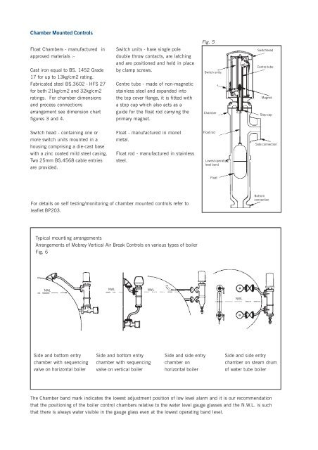
Chamber Mounted Controls<br />
Float Chambers - manufactured in<br />
approved materials :-<br />
Cast iron equal to BS. 1452 Grade<br />
17 for up to 13kg/cm2 rating.<br />
Fabricated steel BS.3602 - HFS 27<br />
for both 21kg/cm2 and 32kg/cm2<br />
ratings. For chamber dimensions<br />
and process connections<br />
arrangement see dimension chart<br />
figures 3 and 4.<br />
Switch head - containing one or<br />
more switch units mounted in a<br />
housing comprising a die-cast base<br />
with a zinc coated mild steel casing.<br />
Two 25mm BS.4568 cable entries<br />
are provided.<br />
Switch units - have single pole<br />
double throw contacts, are latching<br />
and are positioned and held in place<br />
by clamp screws.<br />
Centre tube - made of non-magnetic<br />
stainless steel and expanded into<br />
the top cover flange, it is fitted with<br />
a stop cap which also acts as a<br />
guide for the float rod carrying the<br />
primary magnet.<br />
Float - manufactured in monel<br />
metal.<br />
Float rod - manufactured in stainless<br />
steel.<br />
For details on self testing/monitoring of chamber mounted controls refer to<br />
leaflet BP203.<br />
Typical mounting arrangements<br />
Arrangements of <strong>Mobrey</strong> Vertical Air Break Controls on various types of boiler<br />
Fig. 6<br />
NWL NWL NWL<br />
Side and bottom entry<br />
chamber with sequencing<br />
valve on horizontal boiler<br />
Side and bottom entry<br />
chamber with sequencing<br />
valve on vertical boiler<br />
Side and side entry<br />
chamber on<br />
horizontal boiler<br />
Fig. 5<br />
Switch units<br />
Chamber<br />
Switchhead<br />
Centre tube<br />
Side and side entry<br />
chamber on steam drum<br />
of water tube boiler<br />
The Chamber band mark indicates the lowest adjustment position of low level alarm and it is our recommendation<br />
that the positioning of the boiler control chambers relative to the water level gauge glasses and the N.W.L. is such<br />
that there is always water visible in the gauge glass even at the lowest operating band level.<br />
Float rod<br />
Lowest operating<br />
level band<br />
Float<br />
NWL<br />
Magnet<br />
Stop cap<br />
Side connection<br />
Bottom<br />
connection