

Mobrey - Warren Bestobell
Mobrey - Warren Bestobell
Mobrey - Warren Bestobell

Create successful ePaper yourself
Turn your PDF publications into a flip-book with our unique Google optimized e-Paper software.
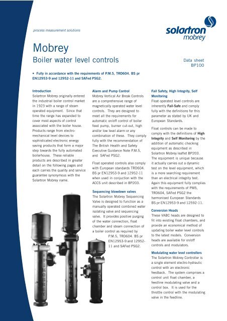
process measurement solutions<br />
<strong>Mobrey</strong><br />
Boiler water level controls<br />
• Fully in accordance with the requirements of P.M.5, TRD604. BS pr<br />
EN12953-9 and 12952-11 and SAFed PSG2.<br />
Introduction<br />
Solartron <strong>Mobrey</strong> originally entered<br />
the industrial boiler control market<br />
in 1923 with a range of steam<br />
operated equipment. Since that<br />
time the range has expanded to<br />
cover most aspects of control<br />
associated with the boiler house.<br />
Products range from electromechanical<br />
level devices to<br />
sophisticated electronic energy<br />
saving products that form a major<br />
step towards the fully automated<br />
boilerhouse. These reliable<br />
products are described in greater<br />
detail on the following pages and<br />
each carries the quality and service<br />
guarantee synonymous with the<br />
Solartron <strong>Mobrey</strong> name.<br />
Alarm and Pump Control<br />
<strong>Mobrey</strong> Vertical Air Break Controls<br />
are a comprehensive range of<br />
magnetically operated water level<br />
controls. They are designed to<br />
meet all the requirements for<br />
automatic on/off control of boiler<br />
feed pump, burner cut-out, high<br />
and/or low level alarm or any<br />
combination of these. They comply<br />
fully with the recommendation of<br />
The British Health and Safety<br />
Executive Guidance Note P.M.5,<br />
and SAFed PSG2.<br />
Float operated controls also comply<br />
with European standards TRD604.<br />
BS pr EN12953-9 and 12952-11<br />
when used in conjuction with the<br />
ACCS unit described in BP203.<br />
Sequencing blowdown valves<br />
The Solartron <strong>Mobrey</strong> Sequencing<br />
Valve is designed to function as a<br />
manually operated combined water<br />
isolating valve and sequencing<br />
valve. It provides positive purging<br />
of the water connection, float<br />
chamber and steam connection of<br />
a boiler control as required by<br />
P.M.5, TRD604. BS pr<br />
EN12953-9 and 12952-<br />
11 and SAFed PSG2.<br />
1234<br />
Data sheet<br />
BP100<br />
Fail Safety, High Integrity, Self<br />
Monitoring<br />
Float operated level controls are<br />
inherently Fail-Safe and comply<br />
fully with the definitions for this<br />
parameter as stated by UK and<br />
European Standards.<br />
Float controls can be made to<br />
comply with the definitions of High<br />
Integrity and Self Monitoring by the<br />
addition of automatic checking<br />
equipment as described in<br />
Solartron <strong>Mobrey</strong> leaflet BP203.<br />
The equipment is unique because<br />
it actually carries out a dynamic<br />
test on the level equipment, which<br />
is a more searching requirement<br />
than an electrical integrity test.<br />
Again this equipment fully complies<br />
with the requirements of PM5,<br />
TRD604, SAFed PSG2 the<br />
harmonised European Standards<br />
BS pr EN12953-9 and 12592-11.<br />
Conversion Heads<br />
These VABC heads are designed to<br />
fit into existing float chambers, and<br />
provide an economical method of<br />
updating boiler water level controls<br />
to the latest models. Conversion<br />
heads are available for on/off<br />
controls and modulators.<br />
Modulating water level controllers<br />
The Solartron <strong>Mobrey</strong> Controller is<br />
a single element electro-hydraulic<br />
control with an electronic<br />
feedback. The system comprises a<br />
control unit float chamber, a<br />
feedline modulating valve and a<br />
control box. It is used for the<br />
throttle control with the modulating<br />
valve in the feedline.
Vertical air break alarm and pump controls<br />
Description<br />
The Solartron <strong>Mobrey</strong> Vertical Air<br />
Break Controls (VABC) are a<br />
comphrensive range of magnetically<br />
operated water level controls for<br />
steam boilers. They are designed to<br />
meet all requirements for automatic<br />
on/off control of boiler feed pump,<br />
burner cut out, high and/or low level<br />
alarm or any combination of these<br />
complying fully with the<br />
recommendations of the British<br />
Health and Safety Executive, PM5<br />
and SAFed PSG2 as well as<br />
European Standards TRD604, and<br />
BS pr EN12952-11 and 1253-9<br />
when used in conjunction with the<br />
ACCS unit. See BP203. Refer to<br />
Fig. 6 for typical installations.<br />
Models available with Industrial<br />
(NEMA4), or Marine Heads.<br />
TUV approved models are available<br />
in Chambers and for Direct<br />
Mounting on application.<br />
Operation<br />
The Solartron <strong>Mobrey</strong> VABC is of<br />
glandless constuction. A primary<br />
permanent magnet attached to the<br />
float rod slides vertically inside a nonmagnetic<br />
stainless steel centre tube<br />
and transmits the movements of the<br />
float to a secondary magnet in each<br />
switch unit. There are two pairs of<br />
contacts which are operated with a<br />
snap action and held by repulsion<br />
between the secondary magnet and<br />
the tertiary magnet of the switch unit<br />
assembly.<br />
Operating Levels<br />
Differentials<br />
Each switch has a nominal fixed<br />
water level differential of 25mm<br />
between circuits A-A and B-B.<br />
To obtain a differential greater than<br />
25mm, two switch units must be<br />
used.<br />
The minimum water level differential<br />
for two switch units is 33mm, with<br />
switch centres positioned 8mm<br />
apart.<br />
62mm range 37mm adjustment + 25mm fixed differential = 62mm<br />
150mm range 125mm adjustment + 25mm fixed differential = 150mm<br />
250mm range 225mm adjustment + 25mm fixed differential = 250mm<br />
Fig. 1<br />
62mm Single switch<br />
Maximum<br />
switching<br />
range<br />
62mm<br />
Electrical Characteristics<br />
Single-pole double-throw operation<br />
for :<br />
AC<br />
Maximum voltage 440V<br />
Maximum Current 5A<br />
Minimum Power Factor 0.4<br />
Maximum Power 2000VA<br />
DC<br />
Resistive<br />
Maximum Power 100W<br />
Maximum Voltage 250V<br />
Maximum Current 5A<br />
Inductive<br />
Maximum Voltage 250V<br />
*Maximum Current 0.5A<br />
Maximum Time Constant 40 ms<br />
Maximum Power 100W<br />
*Maximum up to 2A dependent<br />
upon time constant of ciruit, consult<br />
factory<br />
Upper stop<br />
Maximum<br />
switching<br />
range<br />
150mm or<br />
250mm<br />
Lower stop<br />
The maximum adjustable differential<br />
for two switch machines will vary<br />
with the operating range of each<br />
model, i.e. the distance between<br />
rising and falling level which is<br />
required to operate the switches<br />
positioned at the extreme ends of<br />
their adjustments - Fig. 2.<br />
Switch adjustment - Fig. 1 and 2.<br />
Switches have adjustments as<br />
follows:<br />
Fig. 2<br />
150 or 250mm Range two switch<br />
2 x SPST<br />
AA make on rise<br />
BB make on fall<br />
Additional<br />
switches may be<br />
added as<br />
optional extras<br />
A B<br />
A B<br />
Link for SPDT/SPCO<br />
Switches must not be used for the<br />
direct starting of motors. Contacts<br />
should be wired in series with the<br />
operating coils of relays, contact<br />
starters or solenoid valves, and fused<br />
separately.<br />
Two 25mm BS.4568 cable entries<br />
are provided for the electrical<br />
connections. A sufficient length of<br />
flexible cable must be fitted to<br />
permit easy removal of the switch<br />
head and float assembly for routine<br />
maintenance.
Dimensions and ordering information : Chamber mounted models<br />
Fig. 3<br />
Cover<br />
removal<br />
height<br />
H 1<br />
Lowest<br />
operating<br />
level band<br />
Fig. 4<br />
H 1<br />
H<br />
W<br />
Lowest<br />
operating<br />
level band<br />
H<br />
W<br />
100<br />
G<br />
100<br />
Explanation of type numbers<br />
The type numbers are arbitrary<br />
except that BX denotes chamber<br />
mounting and BD direct mounting.<br />
The stroke number indicates the<br />
number of switch units fitted as<br />
standard. When extra switches are<br />
required this stroke number will<br />
indicate the total number of<br />
switches to be provided.<br />
G<br />
100<br />
C<br />
Multi-switch 120, 150,<br />
215, 250mm ranges<br />
L<br />
L<br />
No. of<br />
Dimensions<br />
Type Operating Switches Flanged & Screwed<br />
Number Range Std. Max Connections C G H H2 L W F<br />
Cast iron chamber - working pressure: 13kg/cm<br />
BX02/1 62 1 - BS4504.25-16/11 - 102 193 303 366 182 160<br />
BX05/2 150 2 4 BS4504.25-16/11 - 102 293 502 468 277 160<br />
BX07/2 250 2 6 BS4504.25-16/11 - 102 393 602 557 370 160<br />
BX09/1 62 1 - BS4504.25-40/2 - 87 193 303 366 182 160<br />
BX10/2 150 2 4 BS4504.25-40/2 - 87 293 502 468 277 160<br />
BX11/2 250 2 6 BS4504.25-40/2 - 87 393 602 557 370 160<br />
BX12/1 62 1 - BS4504.25-40/2 - 102 193 303 559 372 160<br />
BX13/2 150 2 4 BS4504.25-40/2 - 100 293 502 559 372 160<br />
BX14/2 250 2 6 BS4504.25-40/2 - 100 393 602 559 372 160<br />
2<br />
Fabricated steel chamber - working pressure: 21kg/cm2 Fabricated steel chamber - working pressure: 32kg/cm2 Type Operating<br />
No. of<br />
Switches Flanged<br />
Screwed<br />
Bottom<br />
Conn.<br />
Dimensions<br />
Number Range Std. Max Connections BSP C G H H1 L W F<br />
BX03/1 62 1 - 25-16/11 1” 216 102 193 303 448 277 160<br />
BX15/1 62 1 - 20-16/11 1” 180 100 193 303 480 240 160<br />
BX87/1 62 1 - 20-16/11 1” 180 135 193 303 480 240 160<br />
BX16/2 120 2 4 20-16/11 1” 180 100 293 303 480 240 160<br />
BX88/2 120 2 4 20-16/11 1” 180 135 293 303 480 240 160<br />
BX06/2 150 2 4 25-16/11 1” 216 102 293 502 448 277 160<br />
BX08/2 250 2 6 25-16/11 1” 317 102 393 597 557 370 160<br />
BX17/2 62 1 - 20-40/2 ½” 270 100 193 303 570 335 160<br />
BX45/1 62 1 - 25-40/2 ½” 270 100 193 303 570 335 160<br />
BX18/2 120 2 4 20-40/2 ½” 270 100 293 303 570 335 160<br />
BX19/2 150 2 4 20-40/2 ½” 270 100 293 497 570 335 160<br />
BX20/2 150 2 4 25-40/2 ½” 270 100 393 497 570 335 160<br />
BX21/2 215 2 6 20-40/2 ½” 270 100 393 602 570 335 160<br />
BX22/2 215 2 6 25-40/2 ½” 270 100 393 602 570 335 160<br />
Fabricated steel chamber - working pressure: 32kg/cm<br />
BX23/1 62 1 - 25-40/2 ½” 350 112 193 303 595 372 160<br />
BX24/2 150 2 4 25-40/2 ½” 350 112 293 497 595 372 160<br />
BX25/2 250 2 6 25-40/2 ½” 350 112 393 597 595 372 160<br />
2<br />
Fabricated steel chamber - working pressure: 21kg/cm2 Cast iron chamber - working pressure: 13kg/cm2 When Marine models are required<br />
the letter ‘M’ should be inserted<br />
after the letters BX and before the<br />
number, e.g., the Industrial and<br />
NEMA 4 Model BX05/2 becomes<br />
BXM05/2 when in Marine<br />
construction.<br />
Marine type approvals:<br />
American Bureau of Shipping<br />
Bureau Veritas<br />
Germanischer Lloyd<br />
Lloyds Register of Shipping<br />
Det Norske Veritas<br />
Russian Maritime Register of<br />
Shipping<br />
TUV approved models (side and<br />
side connections only) are available<br />
on request. Before ordering please<br />
refer to Solartron <strong>Mobrey</strong>.<br />
If the models shown here do not<br />
meet your specific requirements,<br />
please contact Solartron <strong>Mobrey</strong> for<br />
assistance.
Chamber Mounted Controls<br />
Float Chambers - manufactured in<br />
approved materials :-<br />
Cast iron equal to BS. 1452 Grade<br />
17 for up to 13kg/cm2 rating.<br />
Fabricated steel BS.3602 - HFS 27<br />
for both 21kg/cm2 and 32kg/cm2<br />
ratings. For chamber dimensions<br />
and process connections<br />
arrangement see dimension chart<br />
figures 3 and 4.<br />
Switch head - containing one or<br />
more switch units mounted in a<br />
housing comprising a die-cast base<br />
with a zinc coated mild steel casing.<br />
Two 25mm BS.4568 cable entries<br />
are provided.<br />
Switch units - have single pole<br />
double throw contacts, are latching<br />
and are positioned and held in place<br />
by clamp screws.<br />
Centre tube - made of non-magnetic<br />
stainless steel and expanded into<br />
the top cover flange, it is fitted with<br />
a stop cap which also acts as a<br />
guide for the float rod carrying the<br />
primary magnet.<br />
Float - manufactured in monel<br />
metal.<br />
Float rod - manufactured in stainless<br />
steel.<br />
For details on self testing/monitoring of chamber mounted controls refer to<br />
leaflet BP203.<br />
Typical mounting arrangements<br />
Arrangements of <strong>Mobrey</strong> Vertical Air Break Controls on various types of boiler<br />
Fig. 6<br />
NWL NWL NWL<br />
Side and bottom entry<br />
chamber with sequencing<br />
valve on horizontal boiler<br />
Side and bottom entry<br />
chamber with sequencing<br />
valve on vertical boiler<br />
Side and side entry<br />
chamber on<br />
horizontal boiler<br />
Fig. 5<br />
Switch units<br />
Chamber<br />
Switchhead<br />
Centre tube<br />
Side and side entry<br />
chamber on steam drum<br />
of water tube boiler<br />
The Chamber band mark indicates the lowest adjustment position of low level alarm and it is our recommendation<br />
that the positioning of the boiler control chambers relative to the water level gauge glasses and the N.W.L. is such<br />
that there is always water visible in the gauge glass even at the lowest operating band level.<br />
Float rod<br />
Lowest operating<br />
level band<br />
Float<br />
NWL<br />
Magnet<br />
Stop cap<br />
Side connection<br />
Bottom<br />
connection
Conversion Heads<br />
Description<br />
These <strong>Mobrey</strong> Vertical Air Break<br />
control heads are specifically<br />
designed to provide an economic<br />
method of updating old <strong>Mobrey</strong><br />
mercury switch controls to the latest<br />
models. These ‘Conversion Heads’<br />
will fit into existing chambers, and<br />
provide on/off pump control and<br />
alarm function.<br />
Standard<br />
VABC head<br />
Flange to<br />
suit<br />
chamber<br />
Existing<br />
chamber<br />
Standard<br />
float unit (rod<br />
length to suit<br />
chamber)<br />
Conversion Heads are also available<br />
for updating old <strong>Mobrey</strong> Teleflex<br />
Modulators.<br />
A suitably adapted version of the<br />
Modulating Control head and float<br />
unit is provided for fitting into the<br />
existing float chamber. it will be<br />
necessary to replace the feed line<br />
valve with its modern counterpart and<br />
to provide the modern electronic<br />
control box.<br />
Ordering Information<br />
Type Numbers<br />
Old unit<br />
numbers<br />
High and low<br />
alarms<br />
100-MS6/F263<br />
102-MS6/F263<br />
129-MS70/F299<br />
129-MS71/F300<br />
133-MS70/F299<br />
133-MS71/F300<br />
125-MS71/F301<br />
Pump control and<br />
1st low alarms<br />
220-MS12/F284<br />
220-MS16/F284<br />
24-MS12/F216<br />
24-MS16/F216<br />
65-MS26/F22<br />
64-MS26/F280<br />
125-MS72/F295<br />
125-MS76/F295<br />
Single alarms 2nd<br />
low<br />
125-MS73/F296<br />
214-S90/F50<br />
14-S90/F50<br />
215-S90/F50<br />
15-S90/F50<br />
17-S101/F50<br />
18-S90/F50<br />
Modulating<br />
controls<br />
30310<br />
30295<br />
Replacement<br />
unit<br />
C250/2<br />
C250/2<br />
F250/2<br />
F250/2<br />
F250/2<br />
F250/2<br />
F250/2<br />
C150/2<br />
C150/2<br />
C150/2<br />
C150/2<br />
C150/2<br />
C150/2<br />
C150/2<br />
C150/2<br />
Note<br />
In all cases the type number of the<br />
existing equipment must be given<br />
when ordering.<br />
This is to enable us to check the<br />
model number and the float rod<br />
length to be provided.<br />
For the modulating control the basic<br />
information for sizing the valve lid<br />
and seat will be required.<br />
Features<br />
• Save<br />
- Time<br />
- Money<br />
- Inconvenience<br />
• Conforms fully to PM5<br />
requirements.<br />
• Uses existing wiring and<br />
chambers<br />
If you cannot see the model number<br />
of your existing control listed here,<br />
or are unsure of which new model to<br />
order, please do not hesitate to<br />
contact Solartron <strong>Mobrey</strong> for further<br />
information.
Direct mounted water level controllers<br />
Direct mounted models<br />
Standard models<br />
Direct Mounted Vertical Air Break<br />
Controls employ the same principles<br />
of operation and piece parts as the<br />
chamber mounted equivalents except<br />
that the chamber is exchanged for a<br />
large round flange and the tube<br />
assembly for mounting the control<br />
directly on to the boiler shell<br />
connection. A stilling or guide tube<br />
should be provided, which may be<br />
fixed or removable, to ensure that the<br />
float rod is not damaged and the<br />
correct vertical movement is achieved.<br />
Direct mounted controls<br />
incorporating test facilities<br />
These controls have the provision for<br />
testing the operation of the<br />
mechanism without lowering the level<br />
of water in the boiler. Testing can be<br />
initiated manually or by a timer.<br />
U.K. Patent 1279504 or 1473939<br />
and foreign equivalents.<br />
Hydraulic cup test facility<br />
The test is achieved by lowering the<br />
float to the low water alarm level, by<br />
the following means :<br />
Type number Working press.<br />
at saturated<br />
Standard steam kg/cm<br />
BD01/1<br />
BD02/2<br />
BD03/2<br />
BD04/1<br />
BD05/2<br />
BD06/2<br />
2<br />
Operating No of<br />
range switches std.<br />
max.<br />
62 1 1<br />
21.0 150 2 4<br />
250 2 6<br />
62 1 1<br />
32.0 150 2 4<br />
250 2 6<br />
Pressures up to 32kg/cm2 available on request<br />
62<br />
150<br />
250<br />
The float road includes a cup, above<br />
the float, which is fed with water<br />
from the boiler feed pump via small<br />
bore pipework and valves through the<br />
control mounting flange (see fig. 7)<br />
for approximately 24 seconds. The<br />
additional weight overcomes the<br />
buoyancy of the float, causing it to<br />
sink, stop the burner firing and<br />
operate the alarm system. After<br />
closing the test valve in the supply<br />
from the feed pump to the control, a<br />
small hole in the bottom of the cup<br />
drains off the water, permitting the<br />
float to rise to the normal operating<br />
position. Control of the water supply to<br />
the cup can alternatively be by means<br />
of a solenoid valve, which can be<br />
initiated by a timer or a manually<br />
Dimensions and Ordering Informaton : Direct Mounted Models<br />
Hydraulic cup<br />
test facility<br />
BDT01/1<br />
BDT02/2<br />
BDT03/2<br />
Electromagnetic<br />
test facility<br />
H 1<br />
32.0<br />
Switch units<br />
Non-return valve<br />
Test valve<br />
1<br />
2<br />
2<br />
Isolating<br />
valve<br />
Float rod<br />
BDT04/1<br />
21.0<br />
- 1 - BM128mm sq 155 x 90 100 293<br />
BDT05/1<br />
32.0<br />
- 1 - 100-40/2<br />
293<br />
For information on Self monitoring / Self testing <strong>Mobrey</strong> controls, please refer to leaflet BP203.<br />
1<br />
4<br />
6<br />
Float<br />
Fig. 7<br />
Hydraulic cup test facility model<br />
Switch head<br />
Centre tube<br />
Magnet<br />
Cover flange<br />
Stop cap<br />
Hydraulic cup<br />
Drain hole<br />
H<br />
K<br />
Flanged<br />
stilling or<br />
guide tube<br />
4 holes D<br />
Ø13<br />
Lowest possible<br />
operating level<br />
162mm<br />
Boiler tubes 20<br />
H<br />
H1 H<br />
K<br />
K<br />
Flanged<br />
Flanged<br />
stilling or<br />
stilling or<br />
guide tube<br />
guide tube 4 holes<br />
4 holes D<br />
D Ø13<br />
Ø13<br />
Lowest<br />
possible<br />
Lowest<br />
162mm 162mm operating<br />
possible<br />
level<br />
operating<br />
20<br />
level<br />
20 Boiler tubes<br />
Boiler tubes<br />
Single switch direct mounting - Multiple switch direct mounting - Multiple switch direct mounting -<br />
Standard models<br />
Standard models<br />
with hydraulic cup test facility<br />
H 1<br />
Connection K<br />
BS4504<br />
100-40/2<br />
100-40/2<br />
100-40/2<br />
Flanged<br />
stilling or<br />
guide tube<br />
162mm<br />
20<br />
Float dim<br />
length dia<br />
152 x 67<br />
155 x 90<br />
155 x 90<br />
operated push button.<br />
In this design the alarm switch<br />
remains fully adjustable.<br />
Electromagnetic test facility<br />
The switch head includes an<br />
inductive coil below the single switch<br />
subassembly (Fig. 8). This surrounds<br />
an armature located inside the<br />
stainless steel centre tube and fixed<br />
to the float rod.<br />
To initiate the test cycle, the coil can<br />
be energised by a timer or a manually<br />
operated push button and the float<br />
will be thrust downwards to stop the<br />
burner firing and operate the alarm<br />
system. When the coil is deenergised<br />
the float rises to its normal<br />
level. In this design the alarm switch<br />
unit is not adjustable.<br />
Switch units<br />
Magnet<br />
Solenoid<br />
armature<br />
Test valve<br />
Stilling or<br />
guide tube<br />
D<br />
K<br />
H<br />
D<br />
Min<br />
77<br />
100<br />
100<br />
H 1<br />
4 holes<br />
Ø13<br />
Lowest<br />
possible<br />
operating<br />
level<br />
Boiler tubes<br />
Multiple switch direct mounting -<br />
with hydraulic cup test facility<br />
Dimensions<br />
H<br />
193<br />
293<br />
393<br />
193<br />
293<br />
393<br />
193<br />
293<br />
393<br />
Solenoid coil<br />
Stop cap<br />
Float rod<br />
Float<br />
Fig. 8<br />
Electromagnetic test facility model<br />
K<br />
Flanged<br />
stilling or<br />
guide tube<br />
4 holes<br />
Ø13<br />
H 1<br />
303<br />
497<br />
597<br />
303<br />
497<br />
597<br />
303<br />
497<br />
597<br />
497<br />
497<br />
H<br />
H 1<br />
Lowest<br />
possible<br />
182mm<br />
operating<br />
D<br />
level 30<br />
Multiple switch direct mounting -<br />
with hydraulic cup test facility<br />
Max. float<br />
rod length<br />
765<br />
1016<br />
1016<br />
1016
Modulating water level controllers<br />
Description<br />
The Solartron <strong>Mobrey</strong> Modulating<br />
Controller is a single element electrohydraulic<br />
control with an electronic<br />
feedback system comprising:<br />
i) A control unit float chamber,<br />
mounted on the boiler shell,<br />
fitted with an Inductance Coil ‘A’<br />
head assembly which can be<br />
made suitable for either Industrial<br />
or Marine Applications.<br />
ii) A flanged modulating valve, fitted<br />
with an Inductance Coil ‘B’ and<br />
twin solenoid valve assembly,<br />
which is mounted in the boiler<br />
feed water line.<br />
iii)An electronic control box.<br />
Operation<br />
A positive change of water level in<br />
the boiler alters the inductance<br />
value of Coil “A” causing an<br />
imbalance in the system. This<br />
signal is transmitted through the<br />
electronic control box to the<br />
appropriate solenoid valve on the<br />
modulating valve thus producing a<br />
change of hydraulic pressure on the<br />
piston assembly, the movement of<br />
which modulates the flow of water to<br />
the boiler.<br />
Simultaneously this same vertical<br />
travel creates a change in the<br />
inductance value of Coil “B” until<br />
the balance is restored, thus closing<br />
the solenoid valve and hydraulically<br />
locking the modulating valve<br />
spindle. This sequence is repeated<br />
in very small steps until the feed<br />
water input equals the required<br />
evaporation rate of the boiler.<br />
To prevent the modulating valve<br />
Feed tank<br />
Pump<br />
responding to random water<br />
movement against the general<br />
direction of level change, a 13mm<br />
reversal or (dead) band is<br />
incorporated in the electronic<br />
circuitry.<br />
Low water alarm and burner cut out<br />
contacts are also provided within the<br />
control box to operate when the water<br />
level falls to a predetermined<br />
position.<br />
Installation Note:<br />
For the further safety of boilers it is<br />
recommended that the <strong>Mobrey</strong><br />
Control Unit is mounted on a <strong>Mobrey</strong><br />
Sequencing Valve.<br />
The water connection from the boiler<br />
to the float chamber should be as<br />
short as possible and the control<br />
head float chamber should be<br />
mounted close to the gauge glasses.<br />
The chamber band mark indicates<br />
the lowest adjustment position of the<br />
low level alarm and it is our<br />
recommendation that the positioning<br />
of the boiler control chambers relative<br />
to the water level gauges glasses and<br />
the N.W.L. is such that there is<br />
always water visible in the gauge glass<br />
even at the lowest operating band<br />
level. If required our technical staff<br />
will advise on individual installations.<br />
General Note<br />
Models shown are for 21kg/cm²<br />
maximum working pressure. Details<br />
of modules for 32kg/cm² will be<br />
provided on request.<br />
Modulating valve<br />
Feed check<br />
valve<br />
Boiler<br />
Important Notice<br />
Electronic control box must not be<br />
subjected to either vibration or<br />
excessive temperature. It is therefore<br />
recommended that they are NOT<br />
mounted directly on to the boiler<br />
shell.<br />
Features<br />
• Inherently stable<br />
• Easily adjusted for individual<br />
operating requirements<br />
• Instant reversion to hand control<br />
in emergency.<br />
Application Notes<br />
Throttle Control –<br />
• Modulating valve in feed line.<br />
• Suitable for automatic cold start<br />
conditions.<br />
• Used for all pumps capable of<br />
operating against a closed<br />
discharge.<br />
With a rising water level in the boiler,<br />
the modulating valve closes<br />
progressively to reduce the rate of<br />
feed into the boiler. The size of valve<br />
lid is determined by the actual<br />
capacity of the boiler plus an<br />
allowance. See nomogram on page 9.<br />
Power failure and high water<br />
shutdown – with a third solenoid<br />
valve<br />
Where one pump is feeding more than<br />
one boiler it is imperative that a boiler<br />
cannot be overfilled.<br />
Therefore a third solenoid valve can<br />
be installed on the modulating valve<br />
which is operated by either a loss of<br />
power on the boiler control circuit or<br />
the high water alarm. In either case<br />
the valve will be closed and prevent<br />
further water entering the boiler. The<br />
third solenoid valve can be retrofitted<br />
to existing valves.<br />
Common feed pump arrangement<br />
Multi-boiler installations operating on<br />
a common feed system require special<br />
sizing consideration and full details<br />
should be provided so that a suitable<br />
valve can be recommended.
Control Units<br />
Standard control heads and chambers<br />
D<br />
F<br />
E<br />
Type<br />
number<br />
Material<br />
Max. press.<br />
kg/cm2<br />
Connections<br />
A<br />
B<br />
C<br />
D<br />
E<br />
F<br />
G<br />
81006<br />
Cast iron<br />
13<br />
Side &<br />
bottom<br />
BS4504<br />
25-16/11<br />
468<br />
100<br />
102<br />
277<br />
390<br />
430<br />
-<br />
81007<br />
Fabricated<br />
steel<br />
21<br />
Side &<br />
bottom<br />
BS4504<br />
25-40/2<br />
468<br />
100<br />
87<br />
277<br />
390<br />
430<br />
-<br />
81008<br />
Fabricated<br />
steel<br />
21<br />
Side &<br />
side<br />
ND 25<br />
NW 25<br />
570<br />
100<br />
100<br />
335<br />
390<br />
430<br />
270<br />
81951<br />
Forged<br />
steel flange<br />
21<br />
Direct<br />
mounted<br />
BS4504<br />
100/40/2<br />
-<br />
-<br />
-<br />
-<br />
390<br />
430<br />
-<br />
Models are available for up to 32kg/cm2 steam working. Details on request<br />
Control Box Electrical characteristics<br />
Type number 80436 80660<br />
Input supply 240V ac 110V ac<br />
6 Holes Ø 20.0<br />
50/60Hz + 10% 50/60Hz + 10%<br />
4 Holes<br />
Ø 7.1<br />
235<br />
85<br />
B<br />
Modulating Valves<br />
A<br />
42<br />
152<br />
235<br />
254<br />
Ambient temperature: 1 O - 60 O C<br />
Conduit connection 6 holes suitable for PG16<br />
Valve body: Cast steel<br />
Max. feed line pressure: 40kg/cm 2<br />
Min. feed line pressure: 5.3kg/cm 2<br />
Max. feed line temp.: 120 o C<br />
Flanged BS4504-40-40/1<br />
(DIN ND40 NW40)<br />
and BS10 table H<br />
F<br />
E<br />
D<br />
C<br />
C<br />
½” BSP<br />
C<br />
81006 81007 81008<br />
E<br />
B<br />
A<br />
F<br />
E<br />
D<br />
A<br />
D<br />
B<br />
G<br />
B<br />
A<br />
C<br />
Input circuit protected by 1 amp HRC fuse.<br />
Alarm and control relays protected by 2 amp HRC fuses.<br />
Relay contacts voltage free rating:-<br />
Max. voltage 250V ac Max. current 2 amp<br />
Facility available to special order for separate supply to<br />
solenoid valves with 2 amp HRC maximum protection.<br />
Output option: 0-10V available on request.<br />
IMPORTANT NOTICE<br />
Electronic control box must not be subjected to either<br />
vibration or excessive temperature. It is therefore<br />
recommended that they are not mounted directly on to<br />
the boiler shell.<br />
Type number<br />
80310/*<br />
80311/*<br />
80653/*<br />
80486/*<br />
80310/80435/*<br />
80311/80435/*<br />
80653/80435/*<br />
Flanged<br />
Table H<br />
ND40<br />
NW40<br />
NW40<br />
Table H<br />
ND40<br />
NW40<br />
No. of Electrical<br />
solenoid valves supply<br />
2<br />
2<br />
2<br />
2<br />
3<br />
3<br />
3<br />
230V ac 50Hz<br />
230V ac 50Hz<br />
110V ac 50Hz<br />
230V ac 60Hz<br />
230V ac 50Hz<br />
230V ac 50Hz<br />
110V ac 50Hz<br />
* Stroke letter to indicate valve lid size required:<br />
A 200 B 150<br />
C 406 D 140<br />
E 425<br />
Note The internal trim on the Modulating valve can be<br />
changed without the need to replace the valve<br />
should operating conditions change.
Sizing of Valve Lids<br />
A range of valve lids and associated<br />
seats are available and provide linear<br />
flow characteristics. a table of cv<br />
values for water (S.G.=1) is given<br />
below for valve lids in the fully open<br />
position.<br />
Type of Lid Cv = kg/hr for<br />
1 kg/cm²<br />
A 1,690<br />
B 2,260<br />
C 3,030<br />
D 4,100<br />
E 5,480<br />
F 7,480<br />
G 9,840<br />
H 13,520<br />
I 18,480<br />
Note: J Lid available on request<br />
for larger boilers.<br />
<strong>Mobrey</strong> Modulating Level Controller valve size chart<br />
Required flow through<br />
valve Kg/hr<br />
Max rated boiler<br />
output Kg/hr<br />
Formulae for determining the Cv<br />
value and correct size of valve lid are<br />
given below. The pressure drop<br />
across the valve should be 1.4 kg/<br />
cm² or greater – normally, the higher<br />
the pressure drop the better the<br />
degree of control. The lid size is<br />
that with the nearest Cv value above<br />
the calculated value.<br />
In the following example, an<br />
allowance of 0.4 kg/cm² has been<br />
made for all feed line losses. In<br />
practice, the allowance should be<br />
that of the installation under<br />
consideration and may well be in<br />
excess of 0.4 kg/cm², particularly<br />
where the feed pump is remote from<br />
the boiler and/or where an antisyphon<br />
valve adjacent to the boiler<br />
feed check valve has been fitted.<br />
Type of valve lid<br />
CV= Q<br />
P<br />
Where<br />
Q = Actual Evaporation of Boiler plus<br />
15 per cent margin kg/hr.<br />
P = Pump Discharge Pressure kg/cm²<br />
when passing Q quantity of water<br />
minus (Boiler Maximum Working<br />
Pressure plus 0.4 kg/cm²).<br />
Example:<br />
Boiler evaporation (actual)<br />
= 4,000 kg/hr.<br />
Boiler Working Pressure<br />
= 6.6 kg/cm²<br />
Pump Discharge Pressure at<br />
Q quantity<br />
= 11 kg/cm²<br />
Cv= 4,000 + 15%<br />
11—(6.6 + 0.4)<br />
=2.300<br />
Lid required: Type C.<br />
Note: Conversion heads to convert old <strong>Mobrey</strong> Teleflex modulators to the latest models are available.<br />
Pressure drop ��P Kg/cm 2
Sequencing Blowdown Valves<br />
Description<br />
A purpose built flanged isolating<br />
angle and sequencing valve with ½”<br />
BSP screwed drain connection and<br />
back seating features, all valve trims<br />
are in stainless steel. It fully<br />
complies with the recommendations<br />
of Health and Safety Executive<br />
guidance note PM5 - for<br />
automatically controlled steam and<br />
hot water boilers.<br />
Sequence of operation<br />
Function<br />
The <strong>Mobrey</strong> sequencing valve is<br />
designed to function as a combined<br />
water isolating valve and a<br />
sequencing valve to provide positive<br />
purging of the water connection,<br />
float chamber and steam connection<br />
of a boiler control.<br />
Blowdown of float chamber and<br />
connections is effected separately<br />
and in a pre-determined sequence<br />
by the operation of the single<br />
specially designed handwheel.<br />
Fig. 1 Fig. 2<br />
NWL<br />
Normal working valve open<br />
Fig. 3 Mid travel position water<br />
connection purged<br />
Fig. 4<br />
NWL<br />
NWL<br />
NWL<br />
Features<br />
• One valve to provide separate<br />
blowdown of:<br />
- Control Chamber<br />
- Steam Connection<br />
- Water Connection<br />
• Blowdown by predetermined<br />
sequence<br />
• Stainless steel trim<br />
• Back seating ensures packings are<br />
not subjected to continuous<br />
pressure<br />
• Available with Imperial or Metric<br />
flanges<br />
Available for pressures up to 32<br />
kgs/cm²<br />
Chamber, steam and water<br />
connections purged<br />
Fully closed position steam connection<br />
and chamber purged
Dimensions and Ordering Information<br />
Models availble<br />
Type<br />
Number<br />
Flange<br />
Connections<br />
BS4504<br />
Material<br />
Body and<br />
Stuffing Box<br />
Maximum<br />
Working<br />
Pressure Bar<br />
Dimensions<br />
A B C<br />
80938 25-16/11 Cast Iron 13* 83 54 219<br />
80947 25-25/21 Gunmetal 21 83 54 219<br />
80951 25-40/1 Cast Steel 32 83 54 219<br />
81390 BS10 Table H Gunmetal 21 83 54 210<br />
*For Lloyds applications maximum W.P. is 10.5 Bar<br />
Important<br />
Connection to water leg<br />
Mid travel position<br />
½” BSP<br />
Blow down connection to drain<br />
The blowdown connection should be piped directly to an independent covered drain, or tundish with removable lid,<br />
capable of accepting the full discharge without danger of blow-back. The bore of blowdown pipe should not be less<br />
than 12mm and the length should be kept as short as possible. Sight glasses must not be fitted in the blowdown<br />
line.<br />
Blowdown Procedure Card:<br />
Solartron <strong>Mobrey</strong> produce a useful blowdown procedure card, part number BP109, which is available on request.
Associated Boiler Products<br />
Electronic Probes<br />
Solartron <strong>Mobrey</strong> manufactures a<br />
full range of conductive and<br />
capacitive probe controls for<br />
application on steam boilers. This<br />
equipment fully complies with the<br />
latest boiler specifications.<br />
General Level<br />
Solartron <strong>Mobrey</strong> is a level, flow,<br />
pressure, density and viscosity<br />
measurement instrument<br />
company. If you have a problem<br />
we will have the solution<br />
Solartron <strong>Mobrey</strong> Limited<br />
158 Edinburgh Avenue Slough Berks UK SL1 4UE<br />
Tel: 01753 756600 Fax: 01753 823589<br />
e-mail: sales@solartron.com www.solartronmobrey.com<br />
Automatic Control Check<br />
System<br />
This product has been designed<br />
to provide high integrity and selfmonitoring<br />
to float operated<br />
controls in compliance with the<br />
latest boiler standards<br />
Smoke Density<br />
Self-calibrating, Obscuration<br />
Meters available on request<br />
For UK and Eire markets only – Full customer service provision<br />
Solartron <strong>Mobrey</strong> GmbH Deutschland tel: 0211/99 808-0<br />
Solartron <strong>Mobrey</strong> Ltd China tel: 021 6353 5652<br />
Solartron <strong>Mobrey</strong> sp z o o Polska tel: 022 871 7865<br />
Solartron <strong>Mobrey</strong> AB Sverige tel: 08-725 01 00<br />
Solartron <strong>Mobrey</strong> SA France tel: 01.30.17.40.80<br />
Solartron <strong>Mobrey</strong> SA-NV Belgium tel: 02/465 3879<br />
Solartron <strong>Mobrey</strong> USA tel: (281) 398 7890<br />
The right is reserved to amend<br />
details given in this publication<br />
without notice<br />
Steam and water Flow<br />
Flow meters are available for<br />
steam, water and fuel flow<br />
measurement using orifice and<br />
low energy loss averaging pitot<br />
tube technology. Non intrusive<br />
meters are available for liquid<br />
flow.<br />
TDS Control, Timed Bottom<br />
Blowdown,<br />
Remote Alarm & Shut down<br />
panels<br />
Solartron <strong>Mobrey</strong> is able to provide a full design, installation, commissioning and maintenance service for their<br />
site installed instrumentation through their service division, <strong>Bestobell</strong> Service. This organisation is able to provide<br />
a full boiler house installation and maintenance service and provide turnkey installation solutions covering all<br />
control and instrumentation functions. The following gives a typical list of operations carried out by engineers and<br />
technicians directly employed by the company and operating through 5 regional offices throughout the UK<br />
� Total compliance with<br />
unmanned boiler regulations,<br />
Health and Safety guidance<br />
note PM5, SAFed PSG2, and<br />
BS prEN12953-9 and BS<br />
prEN12952-11 for both existing<br />
<strong>Mobrey</strong> float controls and<br />
electronic probe installation<br />
� Steam and water flow monitoring,<br />
heat and mass flow calculation<br />
Insurance inspection High integrity, selfmonitoring<br />
float controls<br />
using Solartron <strong>Mobrey</strong>’s unique<br />
range of products.<br />
� Tank and level monitoring<br />
solutions using Solartron<br />
<strong>Mobrey</strong>’s unique range of<br />
products.<br />
� Complete automation solutions<br />
bringing together major<br />
manufacturers equipment into<br />
a single turnkey solution<br />
Electronic probe<br />
installation<br />
<strong>Bestobell</strong> Service is an<br />
engineering company providing<br />
engineering solutions and is a full<br />
operating division of Solartron<br />
<strong>Mobrey</strong>.<br />
Flowmetering<br />
Head Office Scotland & N Ireland Northwest and Eire Northeast<br />
Tel: 01753 756634 Tel : 0141 613 1441 Tel : 0161 483 0931 Tel : 01924 441960<br />
756622 Fax: 0141 613 2093 Fax: 0161 483 4145 Fax: 01924 441850<br />
756623<br />
Fax: 01753 579523 Midlands Southern<br />
Tel : 0121 730 1900 Tel : 01474 355976<br />
Fax: 0121 730 3004 Fax: 01474 564349<br />
a Roxboro Group Company<br />
1234<br />
������<br />
BP100<br />
Mar 03