Electrospray ionization source geometry for mass spectrometry: past ...
Electrospray ionization source geometry for mass spectrometry: past ...
Electrospray ionization source geometry for mass spectrometry: past ...

You also want an ePaper? Increase the reach of your titles
YUMPU automatically turns print PDFs into web optimized ePapers that Google loves.
Trends Trends in Analytical Chemistry, Vol. 25, No. 3, 2006<br />
as high per<strong>for</strong>mance liquid chromatography (HPLC) and<br />
capillary electrophoresis (CE). This has brought new<br />
challenges in generating ions at different flow rates,<br />
minimizing contamination of the interface, and optimizing<br />
overall efficiency. Leading instrument manufacturers<br />
are directly involved in providing innovative<br />
solutions to the industry’s demand <strong>for</strong> more sensitive,<br />
reliable <strong>mass</strong> spectrometers.<br />
The purpose of this review is to present some milestones<br />
in the evolution of the ESI <strong>source</strong> to achieve the<br />
designs and the capabilities currently offered by commercial<br />
manufacturers. We discuss some important<br />
developments achieved by research groups with respect<br />
to ESI design. We also present a basic theoretical background<br />
on droplet <strong>for</strong>mation and current theories of gas<br />
phase ion creation in order to provide the reader with a<br />
better understanding of the reasoning behind the modifications<br />
in <strong>source</strong> design. While other atmospheric<br />
pressure ion <strong>source</strong>s use similar geometries, this review<br />
will focus on only electrospray <strong>ionization</strong>.<br />
3. Theory<br />
A number of publications have presented details of the<br />
electrochemical nature of the electrospray process [4–6].<br />
When a large potential difference is applied between an<br />
electrode shaped as a wire and a counter electrode, a<br />
strong electric field is created at the tip. In the case of ESI,<br />
a high voltage is applied to a capillary containing the<br />
analyte solution. For simplicity, we consider the application<br />
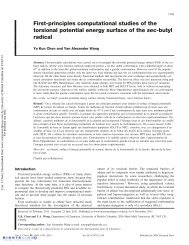
of positive potential only. Due to the electric field<br />
gradient at the tip, charge separation occurs in the<br />
solution as anions migrate towards the capillary walls,<br />
and cations travel towards the meniscus of the droplet<br />
<strong>for</strong>med at the tip (Fig. 1) [7].<br />
In order to direct charged species into the <strong>mass</strong> spectrometer,<br />
a series of counter electrodes is used in order of<br />
decreasing potential. Typically, the principal counter<br />
sample<br />
solution<br />
HV<br />
_ _ _ _ _ _ _ _ _<br />
+<br />
+<br />
+ +<br />
_ _ _ _ _ _ _ _ _ + +<br />
+<br />
+ +<br />
+ + + +<br />
_ _<br />
_ +<br />
_ + _+<br />
+ +<br />
+ _ +<br />
+<br />
_<br />
Taylor<br />
cone<br />
+ +<br />
E<br />
evaporation<br />
+ +<br />
+ +<br />
+ +<br />
+<br />
+<br />
+<br />
_<br />
_<br />
_<br />
offspring<br />
droplets<br />
ions<br />
and<br />
neutrals<br />
Figure 1. Schematic diagram of the electrospray process.<br />
244 http://www.elsevier.com/locate/trac<br />
counter<br />
electrode<br />
electrode can be either the curtain plate of the <strong>mass</strong><br />
spectrometer or a transport capillary, which will be<br />
discussed later. The optimal potential difference between<br />
the sprayer and the principal counter electrode depends<br />
on experimental parameters, such as the charge state of<br />
the analyte, the solution flow rate, the solvent composition,<br />
and the distance between the tip and the counter<br />
electrode. While different <strong>mass</strong> spectrometers may require<br />
different applied voltages on the sprayer and the<br />
counter electrode, the potential difference between them<br />
is similar (typically 2–5 kV) [8]. In the presence of an<br />
electric field, liquid emerges from the tip of the capillary<br />
in the shape of a cone, also known as the ‘‘Taylor cone’’<br />
(Fig. 1) [9]. When the electrostatic repulsion between<br />
charged molecules at the surface of the Taylor cone<br />
approaches the surface tension of the solution – known<br />
as reaching the Rayleigh limit – charged droplets are<br />
expelled from the tip. The droplets containing excess<br />
positive charge generally follow the electric field lines at<br />
atmospheric pressure toward the counter electrode.<br />
However, trajectories will also be affected by space<br />
charge and gas flow.<br />
The mechanism of <strong>for</strong>ming the Taylor cone is not<br />
entirely understood, but it is known that, under certain<br />
conditions, the morphology of the spray emitted from the<br />
capillary tip can change [10]. The various spray modes<br />
strongly depend on the capillary voltage and are related<br />
to pulsation phenomena observed in the capillary current<br />
[10]. Juraschek and Röllgen showed that liquid flow<br />
rate, capillary diameter, and electrolyte concentration<br />
can all impact the spray mode. Controlling the spray<br />
mode is thus crucial in achieving a stable spray and<br />
an optimal signal. However, this becomes particularly<br />
difficult when the mobile phase composition changes<br />
during gradient elution conditions necessary in many<br />
LC-MS applications. To address this problem, Valaskovic<br />
and Murphy have developed an orthogonal optoelectronic<br />
system capable of identifying many spray modes<br />
under different conditions [11]. The system automatically<br />
optimizes the ESI potential in response to changes<br />
in flow rate and solvent composition.<br />
The size of the spray droplets released from the Taylor<br />
cone, highly dependent on flow rate and capillary<br />
diameter, is critical to the efficient <strong>ionization</strong> of the<br />
analyte.<br />
Since a small droplet contains less solvent, desolvation<br />
and <strong>ionization</strong> can be more efficient. Because less fission<br />
is required to produce ions, the salt concentration in the<br />
final offspring droplets may be lower compared to a<br />
droplet that has undergone more evaporation-fission<br />
cycles. As a result, the background noise in the <strong>mass</strong><br />
spectrum may be reduced [12]. In addition, with smaller<br />
droplets, analytes that are not surface active will have a<br />
greater chance of being transferred to the gas phase<br />
rather than being lost in the bulk of the parent droplet<br />
residue [12].