Electrospray ionization source geometry for mass spectrometry: past ...
Electrospray ionization source geometry for mass spectrometry: past ...
Electrospray ionization source geometry for mass spectrometry: past ...

Create successful ePaper yourself
Turn your PDF publications into a flip-book with our unique Google optimized e-Paper software.
Trends Trends in Analytical Chemistry, Vol. 25, No. 3, 2006<br />
4.2. The CE-MS interface<br />
While ion spray became standard <strong>for</strong> LC-MS at higher<br />
flows, CE-MS coupling was more complicated due to the<br />
large variety of solvent compositions required <strong>for</strong> separation<br />
and problems associated with electrochemistry. In<br />
addition, differences in flow rate requirements also<br />
presented problems. Three common ways of interfacing<br />
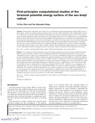
CE-MS are shown in Fig. 6.<br />
The most common method of CE-MS interfacing is the<br />
coaxial sheath flow interface, first described by Smith<br />
et al. in 1988 [38]. In 2003, approximately 77% of CE-<br />
MS users employed this type of interface, due to its<br />
reproducibility and robustness [39]. By allowing a conducting<br />
liquid to provide electrical contact between the<br />
stainless steel capillary maintained at high voltage and<br />
the fused silica capillary carrying the analyte solution,<br />
the interfacing of capillary zone electrophoresis (CZE)<br />
with ESI-MS could be achieved with many buffer systems<br />
that were previously impractical. This is significant because<br />
aqueous buffers of high ionic strength are normally<br />
not tolerated by ESI-MS. Buffer ions can lead to<br />
charge neutralization and corona discharge as well as<br />
<strong>for</strong>mation of undesirable adducts with the analyte<br />
resulting in loss of signal and high sensitivity and high<br />
background. By using organic solvents, such as acetonitrile<br />
or methanol, as the sheath liquid, buffers of ionic<br />
strength up to 0.2 M can be used. The sheath liquid<br />
prevents direct contact between the high voltage elec-<br />
a nebulizer gas<br />
sheath liquid<br />
stainless steel<br />
capillary/electrode <strong>for</strong><br />
CZE / ESI voltage<br />
application<br />
b<br />
nebulizer gas<br />
c<br />
H.V.<br />
nebulizer gas tube<br />
analyte/buffer solution<br />
analyte/buffer solution<br />
separation capillary<br />
separation capillary with conductive<br />
coating <strong>for</strong> ESI voltage application<br />
liquid junction<br />
nebulizer gas<br />
to MS<br />
analyte/buffer solution<br />
separation capillary<br />
to MS<br />
to MS<br />
Figure 6. Schematic of the three most common ways to interface<br />
CE-MS: a) coaxial sheath flow; b) sheathless; and, c) liquid junction.<br />
248 http://www.elsevier.com/locate/trac<br />
trode and the analyte solution, thus avoiding electrochemical<br />
modification of analytes. An additional<br />
advantage of using the sheath flow interface is minimization<br />
of corona discharge as a result of reducing the<br />
ionic strength of the sprayed solvent [38].<br />
Olivares et al. developed the sheathless interface in<br />
1987 by using a stainless steel capillary to create electrical<br />
contact with the analyte solution [39]. Accounting<br />
<strong>for</strong> about 11% of CE-MS interfaces in 2003 [40], this<br />
method evolved with a focus on low flow rates <strong>for</strong> improved<br />
sensitivity.<br />
Other sheathless methods were subsequently developed,<br />
such as sharpening the CE-capillary tip in order to<br />
produce a stable spray, while the ESI electrode was made<br />
by installing a piece of gold wire [41] or coating the<br />
capillary end with a metal or alloy [42]. The advantages<br />
of the sheathless interface are that analyte dilution and<br />
ion suppression due to the sheath flow can be eliminated.<br />
Sensitivity can also be improved by up to an order of<br />
magnitude over sheath-flow designs [43].<br />
A third method of interfacing CE-MS was the liquidjunction<br />
interface developed by Henion and colleagues<br />
[44,45]. A liquid junction between the CE capillary and<br />
the ESI emitter was built using a stainless steel tee<br />
equipped with a buffer reservoir. This interface reduced<br />
the complication brought about by the different flow rate<br />
requirements of CE and ESI [46], but peak broadening<br />
and mechanical difficulties limited the general applicability<br />
of this technique [42].<br />
4.3. Miniaturization of electrospray<br />
In an attempt to reduce flow rates and thus produce<br />
smaller droplets to improve the <strong>ionization</strong> efficiency,<br />
various miniaturized ESI <strong>source</strong>s were developed [47].<br />
Caprioli et al. [48,49] developed an on line ESI <strong>source</strong><br />
equipped with a sprayer tip of 10–20 lm internal<br />
diameter and capable of operating at flow rates of 300–<br />
800 nL/min. The emitter was created by burning off the<br />
polyimide coating of a fused silica capillary tip and<br />
tapering it by etching with hydrofluoric acid to give<br />
droplets in the micron-diameter range. Caprioli named<br />
his technique microelectrospray, a term that currently<br />
describes a flow rate range of 0.2–4 lL/min [50].<br />
Operation in this flow-rate regime may involve various<br />
means <strong>for</strong> pulling silica capillaries and applying the<br />
electrospray voltage [51].<br />
In 1995, Caprioli introduced the idea of using the LCcolumn<br />
tip combined with microelectrospray technology<br />
[52] to spray directly towards the <strong>mass</strong>-spectrometer<br />
inlet. This was significant because it triggered the evolution<br />
of analytical LC columns towards miniaturized<br />
versions of microbore and nanobore capillary columns<br />
necessary <strong>for</strong> low flow rate electrospray [50].<br />
Nanoelectrospray, introduced by Wilm and Mann<br />
more than a decade ago [53], was a particularly<br />
successful technique due to its ability to <strong>for</strong>m droplets