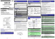
CLAMP ON POWER HiTESTER 3169-20, 3169-21 - Hioki
CLAMP ON POWER HiTESTER 3169-20, 3169-21 - Hioki
CLAMP ON POWER HiTESTER 3169-20, 3169-21 - Hioki
- TAGS
- clamp
- hitester
- hioki
- www.hioki.com

Create successful ePaper yourself
Turn your PDF publications into a flip-book with our unique Google optimized e-Paper software.
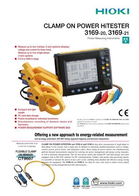
■ Measure up to two 3-phase, 3-wire systems (displays<br />
voltage and current for three lines)<br />
Measure up to four single-phase,<br />
2-wire systems<br />
■ 0.5 A to 5000 A range<br />
■ Compact and light<br />
weight<br />
■ PC card data storage<br />
■ Power recording for individual waveforms<br />
■ Simultaneous recording of demand values and<br />
harmonics<br />
■ <strong>POWER</strong> MEASUREMENT SUPPORT SOFTWARE 9625<br />
Measures power lines of up<br />
to 254 mm in diameter<br />
FLEXIBLE <strong>CLAMP</strong><br />
<strong>ON</strong> SENSOR<br />
CT9667<br />
<strong>CLAMP</strong> <strong>ON</strong> <strong>POWER</strong> <strong>HiTESTER</strong><br />
<strong>3169</strong>-<strong>20</strong>, <strong>3169</strong>-<strong>21</strong><br />
Power Measuring Instruments<br />
The photo shows the <strong>3169</strong>-<strong>21</strong> combined with <strong>CLAMP</strong> <strong>ON</strong> SENSORS 9661 and 9669<br />
(optional) for measuring two systems.<br />
The <strong>3169</strong>-<strong>20</strong>/<strong>21</strong> can also be used in combination with <strong>CLAMP</strong> <strong>ON</strong> SENSORS (optional) rated<br />
up to 5000 A.<br />
Offering a new approach to energy-related measurement<br />
such as energy conservation, ISO14001 testing, equipment diagnosis, and harmonics measurement.<br />
<strong>CLAMP</strong> <strong>ON</strong> <strong>POWER</strong> <strong>HiTESTER</strong>s are <strong>3169</strong>-<strong>20</strong> and <strong>3169</strong>-<strong>21</strong> that allow measurement of single-phase to<br />
three-phase 4-wire circuits with a single unit. In addition to measuring standard parameters such as voltage,<br />
current, power, power factor, and integrated values, these clamp-on power meters can simultaneously<br />
perform demand measurements required for carrying out power management and energy-saving measures,<br />
as well as harmonic measurements. The two new power meters also feature PC card data storage, and come<br />
equipped with an RS-232C interface for PC communications. Further, with greater data processing speeds,<br />
it is possible to measure the power of just a few cycles, enabling more detailed and effective energy-saving<br />
measures for equipment. The <strong>3169</strong>-<strong>20</strong> and <strong>3169</strong>-<strong>21</strong> are ideal for users who want to achieve close control<br />
over energy-saving management activities and measures.
2<br />
Example of use in combination with four <strong>CLAMP</strong> <strong>ON</strong> SENSOR 9661 (optional)<br />
Simultaneous measurement of two 3-phase,<br />
3-wire systems.<br />
Select the clamp-on sensor type most<br />
suited to your measurement needs for each<br />
individual circuit.<br />
<strong>CLAMP</strong> <strong>ON</strong> SENSOR 9661 (500 A AC)<br />
<strong>CLAMP</strong> <strong>ON</strong> SENSOR 9669 (1000 A AC)<br />
(optional)<br />
Features<br />
■ Measure power lines of up to four systems<br />
(with a common voltage)<br />
One single unit can measure four circuits (single-phase 2-wire), two<br />
circuits (3-phase, 3-wire), or a one circuit (3-phase, 4-wire)system.<br />
■ A wide range of measurement functions<br />
The <strong>3169</strong>-<strong>20</strong>/<strong>21</strong> can simultaneously measure voltage, current, power<br />
(active, reactive, and apparent), integrated power, power factor, and<br />
frequency. Further, when using 3-phase, 3-wire (3P3W2M) mode, you<br />
can display the voltage and current for all three lines by measuring just<br />
two of them. When using the 3-phase, 4-wire (3P4W4I) mode, neutral<br />
line current can be displayed using 4 current measurement.<br />
■ Equipped with ranges from 0.5 A to 5000 A<br />
The power meters support seven types of clamp-on current sensors to<br />
enable measurement for a variety of items, from CT terminals to large<br />
current and thick power lines.<br />
■ Supports high-speed data storage from<br />
individual waveforms<br />
When using the standard mode to perform integrated power measurement,<br />
you can store data in intervals starting from one second, and when<br />
simultaneously measuring integration and harmonics, in intervals starting<br />
from one minute. When in the fast mode, you can store RMS data for<br />
individual waveforms.<br />
■ PC Card compatible plus internal hard drive for<br />
extra memory<br />
Store valuable measurement data in convenient PC cards. The internal<br />
memory (1 MB) supports measurement over extended periods and detailed<br />
measurement parameters.<br />
Offering a new measurement<br />
method for energy saving activities<br />
All in a compact A5-size unit<br />
<strong>CLAMP</strong> <strong>ON</strong> <strong>POWER</strong> <strong>HiTESTER</strong> <strong>3169</strong>-<strong>21</strong><br />
(Shown with D/A output)<br />
VOLTAGE CORD L9438-53 (4 provided)<br />
■ Housed in a compact A5 body size<br />
The <strong>3169</strong>-<strong>20</strong> and <strong>3169</strong>-<strong>21</strong> feature a compact design that makes them<br />
portable and easy to use in tight spaces, and are approximately 30%<br />
more compact than the <strong>CLAMP</strong> <strong>ON</strong> <strong>POWER</strong> <strong>HiTESTER</strong> 3166.<br />
■ Multi-language Compatibility<br />
Select from nine languages, including Japanese and English.<br />
■ Detect incorrect connection using vector<br />
diagrams<br />
Use the vector display on the connection confirmation screen to check<br />
the phase, whether a connection is loose, or whether the clamp-on sensor<br />
connection has been reversed during VT/CT terminal measurement.<br />
■ Polarity display and measurement using the<br />
reactive power measurement method<br />
The units come equipped with a polarity display for checking LAG/<br />
LEAD when measuring power factor or reactive power. Further, you<br />
can select the reactive power measurement method, or display the phase<br />
factors for RMS values and power comparison.<br />
■ High-speed D/A output<br />
Simultaneous recording<br />
of a variety of signal and<br />
energy-saving data.<br />
Allows high-speed data transfer to<br />
a PC card for each waveform or at<br />
intervals of 0.1, 0.2, or 0.5 second.<br />
The <strong>3169</strong>-<strong>21</strong> comes equipped with 4-channel high-speed D/A output to<br />
enable analog output of RMS values for individual waveforms.<br />
■ Ideal for power and harmonics management<br />
The power meters come equipped with a harmonics measurement<br />
function that supports measurement of 3-phase power lines. They can<br />
also perform simultaneous measurement of harmonics and demand<br />
values, enabling both power and harmonics management.
The ultimate in clamp-on power meters!<br />
Sleek Design and Engineering<br />
The photo shows the <strong>3169</strong>-<strong>21</strong> with D/A output.<br />
Contrast adjust<br />
volume<br />
Key lock switch<br />
Power inlet<br />
Power switch<br />
Range Configuration Table<br />
Voltage (VOLTAGE CORD L9438-53)<br />
input terminal<br />
Voltage<br />
Current<br />
Connection<br />
Single-phase 2-wire<br />
<strong>CLAMP</strong> <strong>ON</strong> SENSOR 9669<br />
100.00 A <strong>20</strong>0.00 A 1.0000kA<br />
15.000kW 30.000kW 150.00kW<br />
150.00V<br />
Single-phase 3-wire<br />
30.000kW 60.000kW 300.00kW<br />
300.00V<br />
600.00V<br />
Current<br />
<strong>CLAMP</strong> <strong>ON</strong> SENSOR 9695-02<br />
(CAT III 300V)<br />
(500mA, 1A, 5A, 10A, 50A)<br />
<strong>CLAMP</strong> <strong>ON</strong> SENSOR 9694<br />
(CAT III 300V) (500mA, 1A, 5A)<br />
Three-phase 3-wire<br />
Three-phase 4-wire 45.000kW 90.000kW 450.00kW<br />
Single-phase 2-wire 30.000kW 60.000kW 300.00kW<br />
Single-phase 3-wire<br />
Three-phase 3-wire<br />
60.000kW 1<strong>20</strong>.00kW 600.00kW<br />
Three-phase 4-wire 90.000kW 180.00kW 900.00kW<br />
Single-phase 2-wire 60.000kW 1<strong>20</strong>.00kW 600.00kW<br />
Single-phase 3-wire<br />
Three-phase 3-wire<br />
1<strong>20</strong>.00kW 240.00kW 1.<strong>20</strong>00MW<br />
Three-phase 4-wire 180.00kW 360.00kW 1.8000MW<br />
Current (<strong>CLAMP</strong> <strong>ON</strong> SENSOR)<br />
input terminal<br />
External I/O terminal pin placement<br />
D/A output terminal<br />
External I/O terminal<br />
RS-232C port<br />
PC card slot<br />
Pin Signal name Pin Signal name<br />
1 Start/stop input 4 Data storage input<br />
2<br />
Free<br />
5<br />
GND<br />
3 Status output<br />
Use the C<strong>ON</strong>NECTI<strong>ON</strong> CABLE 9440 to connect to external devices.<br />
<strong>CLAMP</strong> <strong>ON</strong> SENSOR 9661<br />
Voltage<br />
Current<br />
Connection<br />
FLEXIBLE <strong>CLAMP</strong> <strong>ON</strong> SENSOR CT9667<br />
500.00 A 5.0000kA<br />
Single-phase 2-wire 75.000kW 750.00kW<br />
150.00V<br />
Single-phase 3-wire<br />
Three-phase 3-wire<br />
150.00kW 1.5000MW<br />
Three-phase 4-wire 225.00kW 2.2500MW<br />
Single-phase 2-wire 150.00kW 1.5000MW<br />
300.00V<br />
600.00V<br />
(5A, 10A, 50A, 100A, 500A)<br />
<strong>CLAMP</strong> <strong>ON</strong> SENSOR 9660, 9695-03<br />
(CAT III 300V) (5A, 10A, 50A, 100A)<br />
Single-phase 3-wire<br />
Three-phase 3-wire<br />
300.00kW 3.0000MW<br />
Three-phase 4-wire 450.00kW 4.5000MW<br />
Single-phase 2-wire 300.00kW 3.0000MW<br />
Single-phase 3-wire<br />
Three-phase 3-wire<br />
600.00kW 6.0000MW<br />
Three-phase 4-wire 900.00kW 9.0000MW<br />
Note 1: The range configuration table displays the full-scale display values for each measurement range. Note 2:In the table, "unit W" has been replaced with "VA" or "var" for the apparentpower<br />
and reactive power measurement ranges. Note 3:Voltage and current input values 0.4% or less than the measurement range are displayed as "zero". When either the voltage or current<br />
for the power line is zero, the power value is displayed as zero. Note 4:You can display measurement values up to 130% of each measurement range.<br />
3<br />
D/A output terminal pin placement<br />
Use the C<strong>ON</strong>NECTI<strong>ON</strong> CABLE 9441 to connect<br />
to external devices. (Output resistance: 100 Ω)<br />
Pin Signal name<br />
1 D/A output ch1<br />
2 D/A output ch2<br />
3 D/A output ch3<br />
4 D/A output ch4<br />
5 to 8 GND<br />
Voltage Connection<br />
500.00mA 1.0000A 5.0000A 10.000A 50.000A 100.00A 500.00A<br />
Single-phase 2-wire 75.000 W 150.00 W 750.00 W 1.5000kW 7.5000kW 15.000kW 75.000kW<br />
Single-phase 3-wire<br />
150.00V<br />
Three-phase 3-wire<br />
150.00 W 300.00 W 1.5000kW 3.0000kW 15.000kW 30.000kW 150.00kW<br />
Three-phase 4-wire 225.00 W 450.00 W 2.2500kW 4.5000kW 22.500kW 45.000kW 225.00kW<br />
Single-phase 2-wire 150.00 W 300.00 W 1.5000kW 3.0000kW 15.000kW 30.000kW 150.00kW<br />
300.00V<br />
Single-phase 3-wire<br />
Three-phase 3-wire<br />
300.00 W 600.00 W 3.0000kW 6.0000kW 30.000kW 60.000kW 300.00kW<br />
Three-phase 4-wire 450.00 W 900.00 W 4.5000kW 9.0000kW 45.000kW 90.000kW 450.00kW<br />
Single-phase 2-wire 300.00 W 600.00 W 3.0000kW 6.0000kW 30.000kW 60.000kW 300.00kW<br />
600.00V<br />
Single-phase 3-wire<br />
Three-phase 3-wire<br />
600.00 W 1.<strong>20</strong>00kW 6.0000kW 12.000kW 60.000kW 1<strong>20</strong>.00kW 600.00kW<br />
Three-phase 4-wire 900.00 W 1.8000kW 9.0000kW 18.000kW 90.000kW 180.00kW 900.00kW
4<br />
Measure hidden power waste through secure connections, simple measurement<br />
methods, and detailed data capture.<br />
Promises reliable measurement for power demand<br />
requirements!<br />
■ Select from a variety of data, including detailed and harmonics data for multiple circuits<br />
★ To measure multiple systems simultaneously<br />
A single unit can measure two three-phase, 3-wire systems. Further,<br />
you can make individual clamp-on sensor and current range settings<br />
for each system.<br />
Also, in addition to performing simultaneous measurement for up to four systems (single-phase,<br />
2-wire) with a common voltage, you can set the current range individually for each system. Setting<br />
the most suitable current range for both large and small loads allows you to acquire more accurate<br />
measurements.<br />
Measurement for up to four<br />
single-phase, 2-wire systems<br />
Measurement for up to two<br />
three-phase, 3-wire systems<br />
★ Magnetic voltage adapters for hard-to-clip terminals<br />
New magnetic voltage adapters convertible with the Voltage Cords L9438-53<br />
let you accurately detect voltage when the circuit terminals are too shallow<br />
for alligator clips to latch on.<br />
Options<br />
Magnetic Adapter<br />
9804-01, 9804-02<br />
ø11mm<br />
Use the 9661 sensor<br />
to measure a single<br />
system<br />
Use the 9669 sensor to<br />
measure two systems<br />
generally compatible with M6 pan screws<br />
★ Simultaneous power and harmonics management<br />
Use a single unit to simultaneously measure data for power and<br />
harmonics.<br />
All acquired data can be saved onto a PC card.<br />
Power data (including demand data) and harmonics data can be simultaneously saved onto a<br />
PC card or in the unit's internal memory. Further, data for all of the systems being measured<br />
can be saved when measuring multiple circuits. Each of these two new unit's offers a<br />
management system for power and harmonic quality.<br />
★ When measurement accuracy is crucial<br />
The addition of a vector display for viewing the connection status<br />
completes the preparation required for measurement.<br />
Have you ever experienced incorrect measurement results?<br />
The most common cause of incorrect data is a faulty connection. With the <strong>3169</strong>-<strong>20</strong>/<strong>21</strong> you can use<br />
the vector display to check the phase, whether a connection is loose, or whether the clamp-on sensor<br />
connection has been reversed.<br />
Also, you are assured of proper connection when measuring the VT (PT)/CT terminals even if you<br />
cannot see the line you are measuring.<br />
Checking the connection on<br />
the vector display<br />
Accurate and reliable<br />
results<br />
The basic settings are constantly displayed, allowing<br />
you to measure with confidence.<br />
During measurement, in addition to displaying the voltage and current ranges, and VT (PT) and CT<br />
ratios for each system, the unit can also display items such as the measurement interval. Because<br />
the basic settings are constantly visible, you can be confident of obtaining the correct measurement<br />
results.<br />
★ Capture facility data quickly<br />
By using continuous processing to measure individual waveforms, you<br />
can accurately measure data in a relatively short amount of time.<br />
Use the desired measurement method to continuously measure the voltage, current, and power for<br />
individual waveforms, enabling you to obtain accurate data in one second or less. Further, you can<br />
record the maximum, minimum and average values.<br />
★ Measure another device simultaneously<br />
Using the external I/O function, you can obtain even more detailed<br />
measurements for energy conservation.<br />
In addition to measurement start/stop control through external input, you can use this function to<br />
output the measurement start/stop signal for the <strong>3169</strong>-<strong>20</strong>/<strong>21</strong>. Simultaneous recording of a variety<br />
of signals is also possible for equipment when using multiple devices to perform start control and<br />
multi-channel recording.<br />
Simultaneous control<br />
for signals from<br />
equipment<br />
Master control<br />
<strong>3169</strong>-<strong>20</strong><br />
▲<br />
Simultaneous<br />
operation<br />
<strong>3169</strong>-<strong>20</strong><br />
▲<br />
MEMORY<br />
▲ HiCORDER<br />
Synchronous<br />
with master<br />
▲
Large storage capacity to accommodate power and harmonics data for individual<br />
waveforms. Supports energy saving measures that can be carried out from your PC.<br />
Greater flexiblity for energy saving measures through<br />
detailed measurement!<br />
■ Reduce energy consumption by "1%"! Why not try analyzing your energy saving measures?<br />
★ Save measurement details to PC card for extended measurements!<br />
Why not try a shorter data management interval?<br />
With the <strong>3169</strong>-<strong>20</strong>/<strong>21</strong>, you can set the data recording interval to 1 minute. If you are unsure how<br />
to proceed with energy conservation, you can use a large capacity PC card to save measurement<br />
details, then use the data to create a load fluctuation graph and analyze this to help reduce wasted<br />
power consumption.<br />
Further, because you can save a variety of data, including simultaneous recording of power and<br />
harmonics data, waveform data storage, and print-outs of the screen, these two new units help by<br />
storing measurement details.<br />
Measurement conditions: 1-minute recording interval, when using a PC card (256 MB)<br />
Data storage 1P2W × 4 1P3W × 2 3P3W2M × 2 3P3W3M,3P4W<br />
Normal measurement (only saves average,<br />
integrated, and demand values)<br />
170 days <strong>21</strong>2 days <strong>20</strong>0 days 342 days<br />
Normal measurement (saves all items) 90 days 82 days 74 days 124 days<br />
Normal measurement + harmonics<br />
measurement (saves all items)<br />
74 hours 80 hours 60 hours 92 hours<br />
Interval 1P2W × 4 1P3W × 2 3P3W2M × 2 3P3W3M,3P4W<br />
When using a<br />
1 minute 90 days (74 hours) 82 days (80 hours) 74 days (60 hours) 124 days (92 hours)<br />
256 MB PC card 2 minutes 182 days (148 hours) 164 days (162 hours)150 days (1<strong>20</strong> hours)250 days (186 hours)<br />
5 minutes 365 days (15 days) 365 days (16 days) 365 days (12 days) 365 days (19 days)<br />
10 minutes 365 days (30 days) 365 days (32 days) 365 days (24 days) 365 days (38 days)<br />
15 minutes 365 days (46 days) 365 days (50 days) 365 days (38 days) 365 days (58 days)<br />
30 minutes 365 days (92 days) 365 days (100 days) 365 days (76 days) 365 days (116 days)<br />
Measurement conditions: When saving all items using normal measurement, the number of days in<br />
parentheses indicate normal measurement + harmonics measurement,<br />
maximum measurement period of one year<br />
★ Identify even small amounts of power waste using individual waveform measurements<br />
The <strong>3169</strong>-<strong>20</strong>/<strong>21</strong> can help turn you into a keen energy saving specialist.<br />
These two new units allow you to measure power data by recording the RMS values for individual<br />
waveforms.<br />
By measuring just a few seconds of machine cycles or changes in operating patterns of facilities<br />
such as manufacturing equipment, you can grasp power fluctuations over a relatively short amount<br />
of time and view improvements in the form of numerical data. Gain unsurpassed energy savings by<br />
achieving simple improvements around the work environment.<br />
Results can be easily processed using software such as Excel.<br />
★ Improve energy-saving operations and create an energy-efficient facility<br />
Why not try to improve your energy-saving measures using the <strong>3169</strong>-<strong>21</strong>?<br />
Using the D/A output (4 ch) function on the <strong>3169</strong>-<strong>21</strong>, you can simultaneously record a variety of<br />
measurement and control signals for equipment, such as the power fluctuation and temperature/flow<br />
for individual waveforms, onto a HIOKI MEMORY HiCORDER or logger.<br />
A slight reduction in power consumption due to changes in the inverter motor operating patterns or<br />
temperature settings equals to an energy-saving effect.<br />
Accurate recording of<br />
momentary fluctuations in<br />
power, etc.<br />
Simultaneous recording<br />
of power volume<br />
The <strong>3169</strong>-<strong>20</strong>/<strong>21</strong> allows you to view changes that are hard to determine<br />
from numerical data alone.<br />
★ Unbalanced loads are an enemy to energy saving activities.<br />
Solve your problems with careful management of power lines.<br />
Unbalanced 3-phase loads can result in a damaged power line.<br />
To provide detailed management of measurements, the <strong>3169</strong>-<strong>20</strong>/<strong>21</strong> displays voltage and current<br />
for all three lines even when measuring just two circuits (3P3W2M). Further, because the effective<br />
power for each phase is displayed based on a virtual center point when measuring the voltage<br />
and current for all three lines (3P3W3M), the units can also be used to implement energy saving<br />
measures and power management systems.<br />
When measuring with<br />
3P3W3M systems:<br />
Displays the effective<br />
power for individual<br />
phases and the threephase<br />
power values, as<br />
well as the voltage and<br />
current for all three lines<br />
★ Harmonics cause wasted power<br />
Did you think that harmonics and energy saving activities were unrelated?<br />
Due to a spread in equipment that uses semiconductor control devices, such as inverters, power<br />
quality has decreased. Also, power consumed in harmonic components is all wasted power.<br />
Harmonic control and management are essential for energy conservation.<br />
The current direction<br />
of harmonic waves is<br />
obvious<br />
When measuring<br />
3P3W2M systems:<br />
Displays the voltage/current<br />
difference between<br />
each pair of lines and<br />
average values<br />
The degree of distortion<br />
is obvious in the<br />
voltage/current display<br />
You can switch channels to easily check the harmonics for each circuit<br />
★ To identify causal factors with harmonic measurements of multiple systems circuits<br />
If production equipment malfunctions, power is wasted if repeated manufacture results in defective<br />
products again.<br />
If you think harmonics are causing malfunctions, you can simultaneously measure the harmonics<br />
of individual circuits using multi-circuit measurement to obtain detailed information about the<br />
occurrence of harmonics along with the current direction for each phase. Using the <strong>3169</strong>-<strong>20</strong>/<strong>21</strong> you<br />
can accurately determine the relationship for harmonic inflow and outflow between power lines by<br />
analyzing the data acquired simultaneously, and then devising energy-saving measures based on the<br />
cause of the occurrence.<br />
5
6<br />
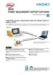
<strong>POWER</strong> MEASUREMENT SUPPORT SOFTWARE 9625<br />
■ Graphically process measurement data from Model <strong>3169</strong>-<strong>20</strong>/<strong>21</strong><br />
easily on a PC!<br />
The <strong>POWER</strong> MEASUREMENT SUPPORT SOFTWARE 9625 application provides easy graphical processing on a<br />
computer of measurement data saved on <strong>CLAMP</strong> <strong>ON</strong> <strong>POWER</strong> <strong>HiTESTER</strong>s <strong>3169</strong>-<strong>20</strong>/<strong>21</strong> and 3166.<br />
<strong>3169</strong>-<strong>20</strong>/<strong>21</strong><br />
Features<br />
3166<br />
Power Data & Harmonic Data<br />
■ Time Series Graph Display Function<br />
Measurement data can be displayed as a time series graph.<br />
Demand data measured in different series can be overlaid on<br />
the display.<br />
■ Summary Display Function<br />
Measurement data can be displayed directly in table form.<br />
Power Data & Harmonic Data<br />
The 9625 handles both power<br />
and harmonic measurement data<br />
simultaneously.<br />
■ Daily, Weekly and Monthly Report Display<br />
Function<br />
Daily, weekly and monthly reports of demand data can be<br />
displayed.<br />
■ Harmonic Analysis Function<br />
Display harmonic measurement data as a graph, list or<br />
waveform. (Also compatible with the harmonic measurement<br />
data captured by Model 3166.)<br />
■ Print Function<br />
Each screen can be printed.<br />
Easily display and print various screens such as graphs and spreadsheet tables<br />
Step 1. Load measurement data<br />
Load up to 16 data sets from the <strong>3169</strong>-<strong>20</strong>/<strong>21</strong> or 3166 at once. Measured<br />
numerical values and waveform data are recognized and displayed<br />
automatically.<br />
1. Loading and deleting data, and changing data names, can be done easily.<br />
2. Multiple sets of measurement data can be loaded and managed in a single<br />
file.<br />
Step 2. Select the display (screen) type<br />
Select from time series graph, summary, daily, weekly or<br />
monthly report, harmonic list, harmonic graph, harmonic<br />
waveform or settings.<br />
Step 3. Select display items (two-axis display is possible)<br />
1. Select the data items (up to 16) to display.<br />
For graph displays, the type of graph (line or bar) can be<br />
selected.<br />
2. Enter details for data display. (data item names, levels, etc.)<br />
Step 4. Set the start/stop times and data interval<br />
to be displayed<br />
1. Set the data period to display. (start/stop time and data interval)<br />
• The displayed period can be easily changed by<br />
scrolling.
■ Time Series Graph Display Function (two-axes display possible)<br />
■ The displayed graph can be set to suit particular start/stop times and<br />
data intervals. Harmonic time series graphs can be displayed.<br />
Convenient Functions<br />
(1) The horizontal (time) axis can be easily scrolled to show the<br />
desired range.<br />
(2) Upper and lower limits (measurement values) of the vertical<br />
axis can be easily set and changed.<br />
* Graph type (line, bar or stacked bar), line type (such as solid or dashed),<br />
color and details of upper and lower numerical values can be set.<br />
(3) Any desired numerical data value on a graph can<br />
be confirmed and displayed by cursor movement.<br />
(4) The display can be switched between 2D and 3D<br />
graphs.<br />
■ Summary Display Function<br />
Summary<br />
■ Displays a summary of the data values between specified start/<br />
stop times, at the specified data interval.<br />
Convenient Functions<br />
(1) In addition to measurement values within the period being<br />
displayed, the summary shows period, maximum, minimum<br />
and average values.<br />
(2) Measurement data names and measurement units can be edited<br />
in the summary.<br />
Daily, Weekly or Monthly Report Display<br />
■ Displays a summary covering the total values in daily, weekly<br />
or monthly reports.<br />
Convenient Functions<br />
(1) The time axis for each total scrolls to easily change the<br />
totalized period.<br />
(2) The total time range of measurement<br />
data can be totalized in up to four<br />
sections per time period.<br />
■ Harmonic Display Function Harmonic data measured by the <strong>3169</strong>-<strong>20</strong>/<strong>21</strong> and 3166 can be displayed in various ways<br />
Harmonic List Display<br />
■ Displays harmonic data for the selected<br />
display item as a list.<br />
Upper/Lower<br />
Limit Setting<br />
Slider<br />
Harmonic Time Series Display<br />
■ While displaying a time series graph, select the harmonic<br />
item for the vertical axis to display a time series graph of<br />
harmonics.<br />
Convenient Functions<br />
(1) Up to 32 graphs can be displayed simultaneously using<br />
2-axes display.<br />
For one circuit measurement, up to 32 orders can be<br />
graphed. Using multiple instruments, time series of<br />
harmonics can be easily compared.<br />
(2) Any desired chronological detail can be easily confirmed<br />
using the cursors on the graph.<br />
View the list to confirm details<br />
Harmonic Graph Display<br />
■ Displays harmonic data for the selected<br />
display item as a bar graph.<br />
Simultaneously display multiple<br />
orders to confirm changes in<br />
harmonics!<br />
Simultaneously display data from<br />
multiple instruments to confirm<br />
concurrent series of harmonics!<br />
Harmonic Waveform Display<br />
■ Displays the voltage and current<br />
waveforms upon which harmonic data<br />
is based.<br />
View the power graph to confirm trends in harmonics View the waveforms to confirm distortion conditions<br />
Cursor Value<br />
7
8<br />
■ Settings Display Function<br />
When you select a data name to be load, the measuring instrument<br />
model and setting conditions at measurement time are displayed.<br />
Measurement data and measurement conditions can be managed<br />
at the same time.<br />
■ 9625 Specifications<br />
■ General Specifications<br />
Supported instrument<br />
models<br />
Operating environment<br />
<strong>3169</strong>-<strong>20</strong>/<strong>21</strong><br />
: <strong>3169</strong>-<strong>20</strong>, <strong>3169</strong>-<strong>21</strong> and 3166(<strong>CLAMP</strong> <strong>ON</strong> <strong>POWER</strong> <strong>HiTESTER</strong>s)<br />
: Computer: PC-AT compatible (DOS/V machine)<br />
CPU: Pentium <strong>20</strong>0 MHz or higher<br />
Memory: 128 MB or more (recommended)<br />
Hard disk: 128 MB or more free space<br />
Display: XGA (1024×768) or higher<br />
Disc device: CD-ROM drive (for installation)<br />
Operating system: Windows <strong>20</strong>00, XP, 7 (English edition)<br />
■ Functional Specifications<br />
[Data/Setting Load/Save Functions]<br />
Loading data /Setting File extension Data format Data contents<br />
Data file CSV CSV<br />
Instantaneous value, average value, maximum value, minimum value,<br />
integrated value, demand value, harmonic<br />
3166<br />
Saved data /Setting File extension Data format<br />
9625 Combined file DAT Binary<br />
Maximum data capacity<br />
[Time Series Graph<br />
Display Function]<br />
Graph display item<br />
Y-axis upper/lower<br />
limit setting<br />
Interval setting<br />
Display period range<br />
setting<br />
Preview printing to confirm print results<br />
before printing<br />
: Up to 528 MB per data set (total composite data up to 1.5 GB)<br />
: Voltage, current, active power, reactive power, apparent power,<br />
power factor, frequency, Integrated value(active power, reactive power),<br />
demand, harmonic (level, content ratio, phase angle, total value, THD)<br />
: The display position (upper and lower display limits) of the vertical<br />
(Y) axis of a graph can be set by scroll bar or by specifying values.<br />
: Select each cycle, or 0.1, 0.2, 0.5, 1, 2, 5, 10, 15 or 30 sec.; 1, 2,<br />
5, 10, 15 or 30 min.; or 1, 2, 3, 4, 6, 8 or 12 h; or 1 day<br />
: An optional analysis period can be specified from the overall<br />
measurement data period<br />
(1) Analysis start date and time (YMD, HMS) is specified numerically<br />
(2) Analysis stop date and time (YMD, HMS) is specified numerically<br />
Display of measurement data period (measurement start<br />
and stop date and time)<br />
■ Print Function<br />
Reports and screen copies of the displayed screen can be easily printed.<br />
Convenient Functions<br />
(1) Printing results can be confirmed by print preview.<br />
(2) When creating a report, screen data can be copied and pasted into a<br />
commercial word processor program.<br />
Supplied Media<br />
Waveform data file WUI Binary Instantaneous waveform<br />
Short-interval data file BIN Binary Instantaneous values<br />
Reference value setting<br />
Graph type selection<br />
Graph line type & color<br />
setting<br />
Stacked bar graph<br />
display<br />
Cursor measurement<br />
Data display units setting<br />
Produce daily, weekly or monthly reports by<br />
one-touch report printing<br />
Integrated measurement data file ITG CSV Instantaneous value, integrated value<br />
Graph copying is also a one-touch operation<br />
: One CD-R disc<br />
Demand measurement data file DEM CSV Instantaneous value, maximum value, minimum value, demand value<br />
Harmonic measurement data file HRM CSV Instantaneous value, average value, maximum value<br />
Waveform data file WUI Binary Instantaneous waveform<br />
Setting file SET –<br />
9625 Combined file DAT Binary<br />
: Display set standard value<br />
: Line, bar, 2-axes and 3-dimensional<br />
: Line type and display color can be set for each data set,<br />
and marker display is possible<br />
: Up to 16 types of data series (demand value, demand quantity )<br />
can be displayed in an overlay graph<br />
: Measurement values can be displayed by the cursor<br />
: Engineering units (m, k, M, G, etc.) can be selected
[Summary Display<br />
Function]<br />
Display item selection<br />
Daily, weekly and<br />
monthly report display<br />
Load factor calculation<br />
display<br />
Independent time range<br />
totalizing<br />
CO2 conversion display<br />
[Harmonic Display<br />
Function]<br />
Waveform display<br />
List display<br />
Graph display<br />
Cursor measurement<br />
[Setting Display<br />
Function]<br />
Setting display<br />
: Select the items to display in the summary<br />
: Displays a report for the specified daily weekly or monthly period<br />
: Calculates the load factor and demand factor as a daily, weekly<br />
or monthly report, and displays the results<br />
: Specify up to four time ranges and totalize data for each time<br />
range independently<br />
: Display the integrated active power (kWh) in CO2 according to<br />
the conversion rate.<br />
: Displays waveform data for a specified time<br />
: Displays a list of harmonic data for a specified time<br />
: Display a bar graph of harmonic data for a specified time<br />
: Displays the value at the cursor with waveform and graph displays<br />
: Displays a list of the setting conditions<br />
Loads setting conditions from a data file (<strong>3169</strong>-<strong>20</strong>/<strong>21</strong>)<br />
Loads setting conditions from a settings file (3166)<br />
■ <strong>3169</strong>-<strong>20</strong>/<strong>21</strong> Specifications<br />
■ Basic Specifications<br />
Measurement line type<br />
Number of systems<br />
that can be measured<br />
(for systems that share<br />
the same voltage)<br />
Item<br />
Measurement range<br />
Measurement method<br />
Input methods<br />
Effective measurement area<br />
Total display area<br />
: Single-phase 2-wire, single-phase 3-wire, three-phase 3-wire, and<br />
three-phase 4-wire systems (50/60 Hz)<br />
:<br />
Single-phase: 1P2W .................................4 systems<br />
1P3W .................................2 systems<br />
Three-phase: 3P3W2M (measures the voltage and current for two lines) ......2 systems<br />
3P3W3M (measures the voltage and current for all three lines) ...1 system<br />
3P4W (measures the voltage and current for three lines) ........1 system<br />
3P4W4I . . . . . . . . . . . . . . . . . . . . . . . . . . . . . . . 1 system<br />
(measures the voltage for three lines and the current for four lines)<br />
: Voltage, current, active power, reactive power, apparent power,<br />
power factor, integrated value, frequency, harmonics<br />
: For the voltage, current, and active power ranges, see the range<br />
configuration tables on page 2.<br />
: Simultaneous digital sampling of voltage and current, PLL synchronization<br />
or a fixed clock (50/60 Hz)<br />
: Voltage: Isolated input<br />
Current: Isolated input using a clamp-on sensor<br />
: Within 5 to 110% of the range<br />
: Voltage and current: Within 0.4 to 130% of the range<br />
(zero is suppressed for less than 0.4%)<br />
Power: Within 0 to 130% of the range<br />
(zero is suppressed when the voltage or current is zero)<br />
Harmonic level: Within 0 to 130% of the range<br />
Display<br />
: 5.7-inch LCD (3<strong>20</strong> × 240 dots), with backlight<br />
Range switching method : Manual (the current range can be set for each system)<br />
Display update rate : Approx. every 0.5 seconds<br />
(except when using a PC card while accessing the internal memory, or when performing RS-232C communications)<br />
Input resistance : Voltage: 2.0 MΩ ± 10% (differential input)<br />
(50/60 Hz)<br />
Current: <strong>20</strong>0 kΩ ± 10%<br />
Maximum input : Voltage input: 780 Vrms AC, peak value: 1103 V<br />
Current input: 1.7 Vrms AC, peak value: 2.4 V<br />
Maximum rated voltage to earth : Voltage input terminals: 600 Vrms AC (50/60 Hz)<br />
Crest factor : Voltage: Less than 2 (for full-scale input)<br />
Current: Less than 4 (for full-scale input. However, less than 2 for the 500 A, 1 kA, and 5 kA ranges)<br />
Internal memory capacity : 1MB<br />
■ Measurement Specifications<br />
[Voltage/current measurement]<br />
Measurement method : True RMS method<br />
Measurement display : Measurement of three voltage lines and 3 or 4 current lines is possible<br />
when using three-phase 3-wire and three-phase 4-wire systems<br />
[Active power measurement]<br />
Measurement display : For three-phase 3-wire (the 3P3W3M setting), refer to the display for<br />
phase power values.<br />
Polarity display : For consumption: no symbol, for regeneration: "-"<br />
[Reactive power measurement]<br />
Using the reactive<br />
power measurement<br />
method<br />
Polarity display<br />
[Apparent power measurement]<br />
Polarity display<br />
[Power factor measurement]<br />
Measurement range<br />
Polarity display<br />
: <strong>ON</strong>: Measures the reactive power directly using the reactive power<br />
measurement method<br />
OFF: Calculates the reactive power from the measurement values for<br />
voltage, current, and active power<br />
: For lag phase (LAG : current is slower than voltage): no symbol<br />
For lead phase (LEAD: current is faster than voltage) : "-"<br />
(Reactive power measurement method "<strong>ON</strong>")<br />
: No polarity<br />
: -1.0000 (lead) to 0.0000 to +1.0000 (lag)<br />
: For lag phase (LAG: current is slower than voltage) :no symbol<br />
For lead phase (LEAD: current is faster than voltage) : "-"<br />
[Frequency measurement]<br />
Measurement range : 40.000 to 70.000 Hz<br />
Input area for : Within 10 to 110% of the range (for sine wave input)<br />
guaranteed accuracy<br />
Measurement source<br />
: Voltage U1<br />
[Copy Function]<br />
Copies to the clipboard<br />
[Print Function]<br />
Printing a displayed time<br />
series graph<br />
Printing a displayed<br />
summary<br />
Printing a harmonic<br />
display<br />
Printing the settings<br />
display<br />
Comment entry<br />
Printing support<br />
[Display Language]<br />
Language<br />
[CSV Format<br />
Conversion Function]<br />
Convertible screens<br />
Instantaneous value<br />
display<br />
Average value display<br />
Maximum/minimum<br />
value display<br />
Integrate display<br />
Demand volume display<br />
(Integrated value within<br />
the specified interval)<br />
Demand value display<br />
(average value within<br />
the specified interval)<br />
Maximum demand value display<br />
(average value within the<br />
maximum specified interval)<br />
Harmonics list<br />
: Each display can be copied to the clipboard<br />
: Previews and prints the contents displayed on a time series graph<br />
: Previews and prints the contents displayed in a summary<br />
: Previews and prints the contents displayed in a harmonic<br />
spreadsheet<br />
: Previews and prints the contents displayed in the settings<br />
display<br />
: Text comments can be entered in any printout<br />
: Any color or monochrome printing supported by the operating<br />
system<br />
: English<br />
■ Display Specifications<br />
: Time-series graph; Summary; Daily,Weekly and Monthly<br />
Report; Harmonic Waveform<br />
: Voltage, current, active power, reactive power, apparent power,<br />
power factor, frequency, average voltage, average current, (average<br />
values are for each system)<br />
: Voltage, current, active power, reactive power, apparent power,<br />
power factor, frequency, average voltage, average current<br />
* The average value from the beginning of time series measurement until the present.<br />
: Voltage, current, active power, reactive power, apparent power,<br />
power factor, frequency<br />
* The maximum/minimum value from the beginning of time series measurement until the present.<br />
: Integrated value<br />
Active power (consumption/regeneration)<br />
Reactive power (lag/lead)<br />
* The total integrated value from the beginning of time series measurement.<br />
: Integrated value<br />
Active power volume (consumption/regeneration)<br />
Reactive power volume (lag/lead)<br />
* The integrated value within each specified interval (latest value).<br />
: Active power (consumption), reactive power (lag), power factor<br />
* The demand value within each specified interval (previous value).<br />
: The maximum demand value since the beginning of time series<br />
measurement and the time and date it occurred.<br />
: List of the items measured for the specified harmonic (numerical<br />
value).<br />
(including the total value and total harmonic distortion factor (THD-F/THD-R))<br />
Harmonics graph : Bar graph or vector diagram of the items measured for the specified<br />
harmonic.<br />
(cursor measurement, magnification update, with a linear/LOG axis selection function)<br />
Waveform display : Voltage and current waveforms (with a magnification update<br />
function)<br />
Measurement value : Select and enlarge up to 5 items from the instantaneous value<br />
enlargement display display.<br />
[Frequency measurement]<br />
Measurement range : 40.000 to 70.000 Hz<br />
Input area for : Within 10 to 110% of the range (for sine wave input)<br />
guaranteed accuracy<br />
Measurement source : Voltage U1<br />
[Integrated measurement]<br />
Measurement range<br />
Measurement display<br />
[Harmonic measurement]<br />
Measurement range<br />
Measurement method<br />
Order for analysis<br />
Window width<br />
Window type<br />
Analysis rate<br />
Item for analysis<br />
: Active power : 0.00000 mWh to 99999.9 GWh consumption<br />
-0.00000 mWh to -99999.9 GWh regeneration<br />
Reactive power : 0.00000 mvarh to 99999.9 Gvarh lag<br />
-0.00000 mvarh to -99999.9 Gvarh lead<br />
: Active power : Displays consumption and regeneration separately<br />
Reactive power : Displays lag and lead separately<br />
: Basic wave frequency: 45 to 66 Hz<br />
PLL synchronization<br />
: Up to the 40th order<br />
: A single cycle (number of data points analyzed: 128 points)<br />
: Rectangular<br />
: 1/16 cycles<br />
: Harmonic level: The voltage, current, or power level for<br />
each harmonic order<br />
: Harmonic content percentage: The voltage, current, or power<br />
content percentage for each harmonic order<br />
: Harmonic phase angle: The voltage, current, or power phase<br />
angle for each harmonic order<br />
: Total value: The total value for voltage, current, or<br />
power up to the 40th harmonic order<br />
: Total harmonic distortion factor: For voltage or current<br />
(THD-F or THD-R)<br />
9
10<br />
■ Setting Specifications<br />
[Setting contents]<br />
Measurement line settings<br />
Clamp-on sensor settings<br />
VT (PT) and CT ratio settings<br />
Measurement start method<br />
Measurement stop method<br />
Output Interval<br />
Data output destination<br />
File name<br />
Display averaging circuit<br />
Screen copy destination<br />
Display language settings<br />
Other settings<br />
[File operations]<br />
Copy file<br />
Load/Save selected file<br />
Delete file<br />
Format<br />
Storage format<br />
: 1P2W, 1P3W, 3P3W2M, 3P3W3M, 3P4W, 3P4W4I<br />
: 9694, 9660, 9661, CT9667(Choose the "9667" setting when using the<br />
CT9667.), 9669, 9695-02 and 9695-03 (* A different sensor can be set<br />
for each system.)<br />
: 0.01 to 9999.99 (* A different CT ratio can be set for each system.)<br />
: Manual or time (year, month, day, hour, minute)<br />
: Manual, time, or timer (1 seconds to 8784 hours)<br />
: Standard or fast (*Maximum measurement period: 1 year)<br />
Standard interval: 1, 2, 5, 10, 15, or 30 seconds, or 1, 2, 5, 10, 15, 30,<br />
or 60 minutes<br />
Fast interval: A single waveform, or 0.1, 0.2, or 0.5 seconds<br />
: PC card, internal memory, or printer<br />
: Automatically attached, or set the desired name<br />
(up to 8 alphanumeric characters)<br />
: OFF, 2, 5, 10, <strong>20</strong> times (for movement averaging)<br />
: PC card, internal memory, or printer<br />
: Japanese, English, German, French, Italian, Chinese (Simple, Trad),<br />
Spanish , Korean<br />
: Reactive power measurement method selection, harmonic distortion<br />
selection, order display selection, backlight settings, ID settings,<br />
clock settings, etc.<br />
: Copies files from the internal memory to the PC card.<br />
: Loads/Saves the file(s) selected from the internal memory or PC card.<br />
: Deletes the file(s) from the PC card.<br />
: Initializes the PC card or internal memory.<br />
: Measurement data: CSV format<br />
(binary format when using the fast interval setting)<br />
Waveform data: Binary format<br />
Screen data: BMP format<br />
Settings data: CSV format<br />
■ External Interface Specifications<br />
[D/A output]<br />
(<strong>3169</strong>-<strong>21</strong> only)<br />
Number of output channels<br />
Output items<br />
Output level<br />
Resolution<br />
Output accuracy<br />
Temperature characteristic<br />
Output resistance<br />
Output update rate<br />
[PC card]<br />
[RS-232C]<br />
[External I/O]<br />
Control input<br />
Control output<br />
Control signal level<br />
: 4 channels<br />
: For instantaneous values: Voltage, current, average voltage, average current,<br />
Active power, reactive power, apparent power,<br />
power factor, frequency<br />
For Integrated value: Active power (consumption/regeneration) or<br />
reactive power (lag/lead)<br />
For harmonics: Each harmonic order (level, content percentage,<br />
and phase angle), total value, THD-F/THD-R<br />
: ±5V DC/f.s.<br />
: Polarity + 11 bits<br />
: Measurement accuracy ±0.2% f.s.<br />
: Less than ±0.02% f.s./°C<br />
: 100Ω ±5%<br />
: For each cycle of measurement input (when a measurement item other than harmonics is set)<br />
For every 16 cycles of measurement input (when harmonics is set as the measurement item)<br />
: Slot: 1 × PC Card Standard-compliant Type II<br />
Card type: Flash ATA card<br />
Compatible memory capacity: Up to 528 MB<br />
Storage content: Settings data, measurement data, screen data<br />
: Printer or PC connected to an RS-232C interface<br />
Compliance: EIA RS-232C-compliant<br />
Transfer method: Asynchronous communication method,<br />
full duplex<br />
Baud rate: 2400, 9600, 19<strong>20</strong>0, 38400 bps<br />
Flow control and delimiter settings possible<br />
: Start/stop control for time series measurement, data storage<br />
: LOW level is output during time series measurement.<br />
: A 0/5 V logic signal or a short-circuit/release contact signal<br />
■ General Specifications<br />
Operating environment<br />
Operating temperature<br />
and humidity<br />
Storage temperature<br />
and humidity<br />
Withstand voltage<br />
(50/60 Hz for 15 sec.)<br />
: Indoors, up to <strong>20</strong>00m (78.74ft) ASL<br />
: 0 to 40˚C, 80% RH or less (non-condensating)<br />
: -10 to 50˚C, 80% RH or less (non-condensating)<br />
: 5.55 kVrms AC: Between the voltage input terminal and the <strong>3169</strong><br />
casing<br />
3.32 kVrms AC: Between the voltage input terminal and the<br />
current input terminal/external interface terminal<br />
2.3 kVrms AC: Between the power supply and the <strong>3169</strong> casing<br />
1.39 kVrms AC: Between the power supply and the current input<br />
terminal/external interface terminal<br />
Power supply voltage rating : 100 to 240 V AC, 50/60 Hz<br />
Maximum rated power : 30 VA<br />
Dimensions and weight : Approx.<strong>21</strong>0(8.27″)W × 160(6.30″) H × 60D(2.36″) mm (excluding<br />
protrusions),<br />
Approx.1.2 kg(42.3oz.) (<strong>3169</strong>-<strong>20</strong>, <strong>3169</strong>-<strong>21</strong>)<br />
[Data output item]<br />
Instantaneous values<br />
Average value<br />
Maximum/minimum value<br />
Integrated value<br />
Demand value<br />
Maximum demand value<br />
Harmonic<br />
Waveform<br />
Status information<br />
[Print items]<br />
Numerical values<br />
Waveform<br />
Conforming standards<br />
Accessories<br />
: Voltage, current, active power, reactive power, apparent power,<br />
power factor, frequency, average voltage, average current, (average<br />
values are for each system)<br />
* The instantaneous value for interval output.<br />
: Voltage, current, active power, reactive power, apparent power,<br />
power factor, frequency, average voltage, average current, (average<br />
values are for each system)<br />
* The average value for each interval.<br />
: Voltage, current, active power, reactive power, apparent power,<br />
power factor, frequency<br />
* The maximum/minimum value for each interval (no event details provided).<br />
: Active power (consumption/regeneration)<br />
Reactive power (lag/lead)<br />
* The total value since the beginning of time series measurement, and the power volume for each interval.<br />
: Active power (consumption), reactive power (lag), power factor<br />
* The value for each interval.<br />
: The maximum demand value since the beginning of time series<br />
measurement and the time and date it occurred.<br />
: Each harmonic order (level, content percentage, and phase angle),<br />
total value, instantaneous value for THD-F/THD-R<br />
: Each harmonic order (level, content percentage, and phase angle),<br />
total value, average value for THD-F/THD-R for each interval<br />
: Each harmonic order (level, content percentage, and phase angle),<br />
total value, maximum/minimum value for THD-F/THD-R within<br />
each interval<br />
(no event data provided)<br />
: Waveform (Voltage or current)<br />
: Exceeds the voltage/current crest factor, PLL unlock, power failure,<br />
exceeds the display limit<br />
■ Formulae<br />
(for single-phase 2-wire systems)<br />
: Prints the data selected as the data output item (during time series<br />
measurement).<br />
: Hard copy of the screen (printing of each interval not available)<br />
U : Inter-line voltage<br />
I : Line current<br />
M : Number of samples<br />
s : Sample count<br />
m : 128 samples per cycle<br />
● Measurement is also possible using the reactive<br />
power measurement method<br />
In addition to conventional calculation methods that search for reactive power<br />
using voltage, current, and active power, you can select the reactive power measurement<br />
method, which derives reactive power directly from voltage and current<br />
values, just as with the reactive power volume measurement method used<br />
in large-volume power consumers.<br />
When using the reactive power measurement method:<br />
Derives reactive power directly from<br />
voltage and current values, just as with<br />
the measurement of active power.<br />
(The same measurement principle is<br />
the same as that used to determine<br />
reactive power by large-volume power<br />
consumers.)<br />
When not using the reactive power measurement method:<br />
Calculates reactive power after calculating<br />
the apparent power using the<br />
voltage, current, and RMS values.<br />
: Safety<br />
EN61010<br />
Pollution degree 2,<br />
measurement category Ⅲ (anticipated transient overvoltage 6000V)<br />
: EMC<br />
EN61326<br />
EN61000-3-2, EN61000-3-3<br />
: voltage cord set L9438-53 (1) (1 cord each of black, red, yellow,<br />
and blue), voltage cord (1), input cord label (1), operating manuals<br />
(2) (Advanced edition and Quick Start Guide), CD-R (1) ( RS-232C<br />
interface operating manuals and CSV conversion Software),<br />
connection cable 9441 (1) (for the <strong>3169</strong>-<strong>21</strong> only)
■ Measurement accuracy (Guaranteed accuracy period : 1 year)<br />
Voltage Current/active power<br />
Conditions of guaranteed accuracy : After 30 minutes of warm-up, sine-wave input, PF=1<br />
Temperature and humidity for : 23˚C ±5˚C, less than 80% relative humidity<br />
guaranteed accuracy<br />
±0.2%rdg.±0.1%f.s. ±0.2% rdg. ±0.1% f.s. + clamp-on sensor accuracy<br />
Fundamental waveform range for : 45 to 66 Hz<br />
guaranteed accuracy<br />
Display area for guaranteed accuracy : Effective measurement area<br />
● Table of current and active power accuracy with clamp-on sensor combinations<br />
Current rang 9694 9695-02 9660, 9695-03 9661 9669 CT9667<br />
0.5A ±0.5%rdg.±0.3%f.s. ±0.5%rdg.±2.1%f.s - - - -<br />
1A ±0.5%rdg.±0.2%f.s. ±0.5%rdg.±1.1%f.s - - - -<br />
5A ±0.5%rdg.±0.12%f.s. ±0.5%rdg.±0.3%f.s ±0.5%rdg.±0.5%f.s. ±0.5%rdg.±1.1%f.s. - -<br />
10A - ±0.5%rdg.±0.2%f.s ±0.5%rdg.±0.3%f.s. ±0.5%rdg.±0.6%f.s. - -<br />
50A - ±0.5%rdg.±0.12%f.s. ±0.5%rdg.±0.14%f.s. ±0.5%rdg.±0.2%f.s. - -<br />
100A - - ±0.5%rdg.±0.12%f.s. ±0.5%rdg.±0.15%f.s.. ±1.2%rdg.±0.2%f.s. -<br />
<strong>20</strong>0A - - - - ±1.2%rdg.±0.15%f.s. -<br />
500A - - - ±0.5%rdg.±0.11%f.s. - ±2.2%rdg.±0.4%f.s.<br />
1000A - - - - ±1.2%rdg.±0.11%f.s. -<br />
5000A - - - - - ±2.2%rdg.±0.4%f.s.<br />
Reference: Accuracy of the <strong>CLAMP</strong> <strong>ON</strong> SENSORE<br />
9694,9695-02, 9695-03, 9660, 9661, 9667, and 9669<br />
• 9694 (rated for 5 A) : ±0.3%rdg.±0.02%f.s.<br />
• 9695-02 (rated for 50 A) : ±0.3%rdg.±0.02%f.s.<br />
• 9695-03 (rated for 100 A): ±0.3%rdg.±0.02%f.s.<br />
• 9660 (rated for 100 A) : ±0.3%rdg.±0.02%f.s.<br />
• 9661 (rated for 500 A) : ±0.3%rdg.±0.01%f.s.<br />
• 9669 (rated for 1000 A) : ±1.0%rdg.±0.01%f.s.<br />
• CT9667 (rated for 5000 A) : ±2.0%rdg.±0.3%f.s.<br />
(500 A range: For 50 to 500 A input)<br />
(5000 A range: For 500 to 5000 A input)<br />
* f.s. is the sensor's rated primary current value.<br />
Note: The table of accuracy for different clamp-on sensor combinations indicates the measurement accuracy for each current range of the <strong>3169</strong>-<br />
<strong>20</strong>/<strong>21</strong>. (The accuracy for each clamp-on sensor is converted and displayed according to the <strong>3169</strong>-<strong>20</strong>/<strong>21</strong> current measurement range.)<br />
Apparent power accuracy : ±1 dgt. for the calculation obtained from each measurement value<br />
Reactive power accuracy : When using the reactive power measurement method<br />
±0.2% rdg. ±0.1% f.s. + clamp-on sensor accuracy<br />
When not using the reactive power measurement method<br />
±1 dgt. for the calculation obtained from each measurement value<br />
Integration accuracy : ±1 dgt. for the measurement accuracy of effective power, reactive power,<br />
and apparent power<br />
Power factor accuracy : ±1 dgt. for the calculation obtained from each measurement value<br />
Frequency accuracy : ±0.5% rdg. ±1dgt.<br />
■Option Specifications<br />
<strong>CLAMP</strong> <strong>ON</strong> SENSOR 9694 9660<br />
Appearance<br />
9661 9669<br />
CAT III 300V CAT III 300V<br />
CAT III 600V CAT III 600V<br />
Primary current rating AC 5 A AC 100 A<br />
AC 500 A<br />
AC 1000 A<br />
Output voltage AC 10mV/A AC 1mV/A AC 1mV/A AC 0.5mV/A<br />
Accuracy Amplitude (45 to 66 Hz) ±0.3%rdg.±0.02%f.s. ±0.3%rdg.±0.02%f.s. ±0.3%rdg.±0.01%f.s. ±1.0%rdg.±0.01%f.s.<br />
Phase (45 Hz to 5 kHz) Within ±2˚ Within ±1˚<br />
Within ±0.5˚ Within ±1˚<br />
Frequency characteristic Within ±1.0% at 40 Hz to 5 kHz (deviation from accuracy)<br />
Within ±2.0% at 40 Hz to 5 kHz (deviation from accuracy)<br />
Effect of external magnetic field Equivalent to 0.1 A or less (with a magnetic field of 400 A/m AC)<br />
Equivalent to 1 A or less (with a magnetic field of 400 A/m AC)<br />
Effect of conductor position Within ±0.5%<br />
Within ±1.5%<br />
Maximum rated voltage to earth 300 V rms<br />
300 V rms<br />
600 V rms<br />
600 V rms<br />
Maximum input (45 to 66 Hz) 50 A continuous 130 A continuous<br />
550 A continuous<br />
1000 A continuous<br />
Measurable conductor diameter Less than φ 15 mm(0.59") Less than φ 15 mm(0.59") Less than φ 46 mm(1.81")<br />
Less than φ 55 mm(2.17"),<br />
80(3.15") × <strong>20</strong> (0.79")mm bus bar<br />
Dimensions and weight<br />
46W(1.81") × 135H(5.31") ×<br />
<strong>21</strong>D(0.83") mm, 230g(9.9oz.)<br />
46W(1.80") × 135H(5.31") ×<br />
<strong>21</strong>D(0.83") mm, 230g(9.9oz.)<br />
77W(3.03") × 151H(5.94") ×<br />
42D(1.65")mm, 380g(12.7oz.)<br />
99.5W(3.92") × 188H(7.40") × 42D(1.65")<br />
mm, 590g(<strong>20</strong>.8oz.)<br />
<strong>CLAMP</strong> <strong>ON</strong> SENSOR<br />
Appearance<br />
CAT III 1000V<br />
CAT Ⅳ 600V<br />
Cord length: 3 m<br />
(9.84ft)<br />
CT9667<br />
Cord length: 3 m<br />
(9.84ft)<br />
Cord length:<br />
Sensor - circuit: 2 m(6.56ft)<br />
Circuit - connector: 1 m(3.28ft)<br />
Primary current rating AC 500 A, 5000A<br />
Output voltage AC 500 mV f.s.<br />
Accuracy Amplitude (45 to 66 Hz) ±2.0%rdg.±0.3%f.s. (for input 10% or more of the renge)<br />
Phase (45 Hz to 5 kHz)<br />
Within ±1˚<br />
Frequency characteristic Within ±3 dB at 10 Hz to <strong>20</strong> kHz (deviation from accuracy)<br />
Effect of external magnetic field 1.5%f.s. or less.. (in a magnetic field of 400 A/m AC, 50/60 Hz)<br />
Effect of conductor position Within ±3.0%<br />
Maximum rated voltage to earth 1000 V rms (CAT Ⅲ), 600Vrms (CAT Ⅳ)<br />
Maximum input (45 to 66 Hz) 10000 A continuous<br />
Measurable conductor diameter Less than φ 254 mm(10.0")<br />
Dimensions and weight<br />
Sensor thickness: φ13 mm (0.51")<br />
Circuit box: 35W(1.38") × 1<strong>20</strong>H(4.74") × 34D(1.34") mm, 470g(16.6 oz.)<br />
Power supply<br />
LR06 alkaline battery × 2 (continuous operation max. 7 days)<br />
or AC ADAPTER 9445-02/9445-03(optional)<br />
Frequency characteristic<br />
Temperature characteristic<br />
Effect of in-phase voltage<br />
Effect of external magnetic field<br />
Power factor influence<br />
Effect of reactive factor<br />
Real-time clock accuracy<br />
CAT III 300V<br />
9695-02<br />
: Fundamental waveforms up to the 50th order ±3% f.s. + measurement<br />
accuracy (of a 45- to 66-Hz fundamental waveform)<br />
: Within ±0.03% f.s./˚C<br />
: Within ±0.2% f.s.<br />
(600 Vrms AC, 50/60 Hz, between voltage input terminal and case)<br />
: Within ±1.5% f.s.<br />
(in a magnetic field of 400 A/m rms AC, 50/60 Hz)<br />
: ±1.0% rdg.<br />
(45 to 66 Hz, power factor = 0.5, for effective power measurement)<br />
: ±1.0% rdg.<br />
(45 to 66 Hz, reactive factor = 0.5, when using the reactive power measurement method)<br />
: ±10 ppm ±1 second (23˚C) (within ±1.9 sec/day (23˚C))<br />
Cord length: 3 m<br />
(9.84ft)<br />
CAT III 300V<br />
9695-03<br />
AC 50 A<br />
AC 100 A<br />
AC 10 mV/A<br />
AC 1 mV/A<br />
±0.3%rdg.±0.02%f.s.<br />
Within ±2˚<br />
Within ±1˚<br />
Within ±1.0% at 40 Hz to 5 kHz (deviation from accuracy)<br />
Equivalent to 0.1 A or less (with a magnetic field of 400 A/m AC)<br />
Within ±0.5%<br />
300 V rms (insulated conductor)<br />
60 A continuous 130 A continuous<br />
Less than φ 15 mm(0.59")<br />
50.5W(1.99") × 58H(2.28") × 18.7D(0.74")mm, 50g(1.8oz.)<br />
Option : C<strong>ON</strong>NECTI<strong>ON</strong> CABLE 9<strong>21</strong>9<br />
Cord length: 3 m<br />
(9.84ft)<br />
11
■Option Specifications<br />
PRINTER 9442<br />
Print method<br />
Paper width<br />
Print speed<br />
Power supply<br />
Dimensions and<br />
weight<br />
Headquarters :<br />
81 Koizumi, Ueda, Nagano, 386-1192, Japan<br />
TEL +81-268-28-0562 FAX +81-268-28-0568<br />
http://www.hioki.co.jp / E-mail: os-com@hioki.co.jp<br />
HIOKI USA CORPORATI<strong>ON</strong> :<br />
TEL +1-609-409-9109 FAX +1-609-409-9108<br />
http://www.hiokiusa.com / E-mail: hioki@hiokiusa.com<br />
: Thermal serial dot printing<br />
: 112 mm(4.41ft)<br />
: 52.5cps<br />
: AC adapter 9443-02, or supplied<br />
nickel-metal hydride battery (approx.<br />
3000 lines of printing when fully<br />
charged and used with the 9443-02)<br />
: Approx.160W (6.30")× 66.5H(2.62") ×<br />
17D(0.67") mm,<br />
approx.580g(<strong>20</strong>.5oz.)<br />
When purchasing the printer 9442, make sure you also purchase the RS-232C<br />
cable 97<strong>21</strong>and AC adapter 9443-02 so that you can connect it to the <strong>3169</strong>-<br />
<strong>20</strong>/<strong>21</strong>.<br />
RS-232C CABLE 97<strong>21</strong><br />
C<strong>ON</strong>NECTI<strong>ON</strong> CABLE 9440<br />
For external I/O<br />
Cord length: 2m(2.65ft)<br />
Cord length for connecting<br />
to the 9442:<br />
1.5 m(4.92ft)<br />
AC ADAPTER 9443-02<br />
For the 9442<br />
C<strong>ON</strong>NECTI<strong>ON</strong> CABLE 9441<br />
For D/A output<br />
(supplied with<br />
the <strong>3169</strong>-<strong>21</strong>)<br />
Cord length: 2 m(2.65ft)<br />
<strong>CLAMP</strong> <strong>ON</strong> <strong>POWER</strong> <strong>HiTESTER</strong> <strong>3169</strong>-<strong>20</strong><br />
(supplied with the voltage cord L9438-53 (1), and power cord (1))<br />
<strong>CLAMP</strong> <strong>ON</strong> <strong>POWER</strong> <strong>HiTESTER</strong><br />
<strong>3169</strong>-<strong>21</strong> (with D/A output)<br />
(supplied with the voltage cord L9438-53 (1), connection cable 9441 (1)<br />
and power cord (1))<br />
Accessory Specifications<br />
VOLTAGE CORD L9438-53 (1 cord each of black, red, yellow, and blue, cord length: 3 m(9.84ft))<br />
C<strong>ON</strong>NECTI<strong>ON</strong> CABLE 9441 (D/A output cable, supplied with the <strong>3169</strong>-<strong>21</strong>)<br />
Current and power cannot be measured using the <strong>CLAMP</strong> <strong>ON</strong> <strong>POWER</strong> <strong>HiTESTER</strong> <strong>3169</strong>-<strong>20</strong>/<strong>21</strong> on<br />
its own. To perform current and power measurement, make sure you also purchase a <strong>CLAMP</strong><br />
<strong>ON</strong> SENSOR (9694, 9660, 9661, CT9667, or 9669) (sold separately).<br />
Use only PC Cards (9727, 9728) sold by HIOKI.<br />
Compatibility and performance are not guaranteed for PC cards made by other manufacturers.<br />
You may be unable to read from or save data to such cards.<br />
● Combination examples<br />
For single-phase 2-wire systems (one system) : <strong>3169</strong>-<strong>20</strong> + 9660(100A) × 1 +9727(256MB)<br />
For single-phase 3-wire systems : <strong>3169</strong>-<strong>20</strong> + 9660(100A) × 2 +9727(256MB)<br />
(one system/two single-phase 2-wire systems)<br />
For three-phase 3-wire systems (one system) : <strong>3169</strong>-<strong>20</strong> + 9661(500A) × 2 +9727(256MB)<br />
For three-phase 3-wire systems : <strong>3169</strong>-<strong>20</strong> + 9661(500A) × 4 +9727(256MB)<br />
(two systems/four single-phase 2-wire systems)<br />
For three-phase 4-wire systems (one system) : <strong>3169</strong>-<strong>20</strong> + 9661(500A) × 3 +9727(256MB)<br />
Note: Company names and Product names appearing in this catalog are trademarks or registered trademarks of various companies.<br />
HIOKI (Shanghai) Sales & Trading Co., Ltd. :<br />
TEL +86-<strong>21</strong>-63910090 FAX +86-<strong>21</strong>-63910360<br />
http://www.hioki.cn / E-mail: info@hioki.com.cn<br />
Beijing Office : TEL +86-10-84418761<br />
FAX +86-10-84418763 / E-mail: info-bj@hioki.com.cn<br />
Guangzhou Office : TEL +86-<strong>20</strong>-38392673<br />
FAX +86-<strong>20</strong>-38392679 / E-mail: info-gz@hioki.com.cn<br />
Shenzhen Office : TEL +86-755-83038357<br />
FAX +86-755-83039160 / E-mail: info-sz@hioki.com.cn<br />
HIOKI INDIA PRIVATE LIMITED :<br />
TEL +91-731-6548081 FAX +91-731-40<strong>20</strong>083<br />
E-mail: info@hioki.in<br />
HIOKI SINGAPORE PTE. LTD. :<br />
TEL +65-6634-7677 FAX +65-6634-7477<br />
E-mail: info@hioki.com.sg<br />
PC CARD 9727, 9728<br />
Use only PC Cards (9727, 9728)<br />
sold by HIOKI.<br />
Models 9729 1G PC Card and 9780 2G<br />
PC Card are not compatible with this<br />
device.<br />
<strong>CLAMP</strong> <strong>ON</strong> ADAPTER 9290-10<br />
C<strong>ON</strong>NECTI<strong>ON</strong> CABLE 9<strong>21</strong>9<br />
Cord length: 3 m(9.84ft) For connection to the 9695-02, 9695-03<br />
Max. 1500 A AC (continuous: 1000 A)<br />
Measurable conductor diameter:<br />
Bus bar : φ55 mm(2.17"), width 80 mm(3.46")<br />
CT ratio: 10:1<br />
*Used for expanding the measurement ranges of the 9660 and<br />
9661 sensors<br />
CARRYING CASE 97<strong>20</strong>-01<br />
A soft type case for storing the <strong>3169</strong>-<strong>20</strong>/<strong>21</strong><br />
and its accessories, such as the clamp-on sensors.<br />
Dimensions<br />
and weight<br />
: Approx. 445W(17.52") × 340H(13.39") ×<br />
150D(5.91") mm,<br />
approx. 2.2 kg(77.6oz.)<br />
■ Options<br />
<strong>CLAMP</strong> <strong>ON</strong> SENSOR 9660 (AC 100A)<br />
<strong>CLAMP</strong> <strong>ON</strong> SENSOR 9661 (AC 500A)<br />
FLEXIBLE <strong>CLAMP</strong> <strong>ON</strong> SENSOR CT9667 (AC 5000A)<br />
<strong>CLAMP</strong> <strong>ON</strong> SENSOR 9669 (AC 1000A)<br />
<strong>CLAMP</strong> <strong>ON</strong> SENSOR 9694 (AC 5A)<br />
<strong>CLAMP</strong> <strong>ON</strong> SENSOR 9695-02 (AC 50A)<br />
<strong>CLAMP</strong> <strong>ON</strong> SENSOR 9695-03 (AC 100A)<br />
C<strong>ON</strong>NECTI<strong>ON</strong> CABLE 9<strong>21</strong>9 (for connection to the 9695-02, 9695-03)<br />
<strong>CLAMP</strong> <strong>ON</strong> ADAPTER 9290-10 (AC 1500A)<br />
C<strong>ON</strong>NECTI<strong>ON</strong> CABLE 9440 (for external I/O)<br />
RS-232C CABLE 9612 (for connection to a PC)<br />
PRINTER 9442<br />
AC ADAPTER 9443-02 (for the 9442, for Europe)<br />
RS-232C CABLE 97<strong>21</strong> (for connection to the 9442)<br />
RECORDING PAPER 1196 (25 m(82ft)/10 rolls, for the 9442)<br />
CARRYING CASE 97<strong>20</strong><br />
<strong>POWER</strong> MEASUREMENT SUPPORT SOFTWARE 9625<br />
PC CARD 256M 9727<br />
PC CARD 512M 9728<br />
MAGNETIC ADAPTER (1 red adapter) 9804-01<br />
MAGNETIC ADAPTER (1 black adapter) 9804-02<br />
DISTRIBUTED BY<br />
MAGNETIC ADAPTER 9804-01, 02<br />
Magnetic tip for use with the standard<br />
Voltage Cord L9438-53<br />
(generally compatible with M6 pan screws)<br />
Red and black adapters sold separately.<br />
Purchase the quantity and color<br />
appropriate for your application.<br />
(Example: 3P3W - 3 adapters; 3P4W - 4 adapters)<br />
Cord length: 3 m(9.84ft)<br />
All information correct as of Aug. 27, <strong>20</strong>12. All specifications are subject to change without notice. <strong>3169</strong>E15-28E Printed in Japan<br />
φ11mm<br />
9804-01<br />
Red<br />
9804-02<br />
Black