Roadtrax BL Traffic Sensors - EHAG Electronic Hardware AG
Roadtrax BL Traffic Sensors - EHAG Electronic Hardware AG
Roadtrax BL Traffic Sensors - EHAG Electronic Hardware AG

Create successful ePaper yourself
Turn your PDF publications into a flip-book with our unique Google optimized e-Paper software.
Dear <strong>Traffic</strong> Professional,<br />
Piezo Polymer <strong>Sensors</strong><br />
Microfused Load Cells<br />
Microfused Pressure Transducers<br />
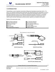
Thank you for your interest in the Measurement Specialties <strong>Roadtrax</strong>7 Piezoelectric <strong>Traffic</strong><br />
<strong>Sensors</strong> for In the Road and Over the Road applications. These sensors are being used for<br />
Weigh in Motion (WIM), vehicle classification and counting, speed detection, red light cameras,<br />
and parking area control.<br />
Enclosed are the Product Specifications and Installation instructions for the <strong>Roadtrax</strong> <strong>BL</strong><br />
Sensor. The <strong>BL</strong> Sensor (named for what it looks like - a Brass Linguini 7 !) is installed directly into<br />
a slot in the road. The sensor is only 1/16" thick and 1/4" wide (1.5mm x 6.5mm), but will provide<br />
500 mV for a car. It is installed in a :" wide by 1" deep (19mm-25mm) slot in the road.<br />
Available in any length, it can be coiled for easy shipping and handling. These sensors reject<br />
road noise 10:1 and reduce ghost axles due to their flat design. This gives your electronics a<br />
clean easy to read signal that translates into more accurate classification, speed, and WIM data.<br />
The <strong>BL</strong> Sensor is available in a Class I (Weigh in Motion) configuration. Both the Class I and<br />
the Class II sensors are available in a variety of different lengths from 6' to 13', with standard<br />
cable lengths of 100' or more (metric lengths of 2 m to 5.5m, with cable lengths standard from<br />
35m to 100m). These sensors are directly compatible with all counters and WIM Systems which<br />
have a piezoelectric input. <strong>Roadtrax</strong> sensors are used worldwide. Collectively, they have<br />
performed in an exemplary manner, giving unrivaled accuracy and dependability.<br />
We are dedicated to working with you to ensure you have the right product to fully fit your needs.<br />
We can assist you in preparing for the installation of the sensors, to ensure it goes smoothly.<br />
We are committed to making the <strong>Roadtrax</strong> traffic sensors the best in the world. We appreciate<br />
the opportunity to work with you on your traffic data collection needs, and to assist you in making<br />
your job easier, safer and at the most cost effective.<br />
An INSTALLATION VIDEO outlining the installation of the <strong>BL</strong> Sensor in the road is available. If<br />
you would like a copy of the video, just let us know and we will be happy to send you a copy. It<br />
is available in both video formats for use throughout the world.<br />
Please give me a call if you have any questions. I would be happy to provide you with any<br />
further information or to quote you for your specific requirements.<br />
Sincerely,<br />
Donald Halvorsen<br />
Donald L. Halvorsen<br />
Director, Business Development<br />
Industriestr. 8 8618 Oetwil a/S. Tel: +41 43 844 94 00 Fax: +41 43 844 94 01 ELECTRONIC HARDWARE <strong>AG</strong><br />
http://www.ehag.ch E-Mail: info@ehag.ch
���� Great Great Signal<br />
Measurement Specialties Inc, Sensor Products Division,<br />
<strong>Roadtrax</strong> <strong>BL</strong> <strong>Traffic</strong> <strong>Sensors</strong><br />
Revised October 2001<br />
The The The MSI MSI <strong>Roadtrax</strong> <strong>Roadtrax</strong><br />
7 7<br />
Brass Brass Linguini Linguini axle axle sensor<br />
sensor<br />
... and why it it=s it<br />
s the the best best sensor sensor for for you!!<br />
you!!<br />
& Positive signal as tires pass over the sensor<br />
& High output - detects small vehicles -<br />
motorcycles, even bicycles<br />
& Good dynamic range - can work with large<br />
to small vehicles<br />
& Reduced Bow Wave<br />
& Reduced Road Flexing noise<br />
& High Signal to Noise Ratio for ease of<br />
signal processing<br />
& High capacitance - can drive long cables<br />
& Works even for slow speeds<br />
���� Easy to handle<br />
& Conforms to any road profile<br />
& Stiff enough not to droop<br />
& Coils in a 2'x2' (600x600mm) box<br />
& Rugged so that it does not break in<br />
handling<br />
���� Easy installation<br />
& Installs in a 3/4" x 1" (19 x 25mm) cut in the<br />
road to minimize damage to the road<br />
& Installs with fast curing epoxy, acrylic, or<br />
appropriate poly-urethane<br />
& No need for heaters<br />
& Smaller cut means less encapsulation<br />
material - a 6' <strong>BL</strong> sensor uses less than 2<br />
gallon (2m sensor uses less that 1.5 liters)<br />
���� Quality<br />
& 100% of sensors tested for capacitance<br />
and insulation resistance, and then<br />
impacted every 1/4" (6mm) along the length<br />
of the sensor to determine the activity and<br />
uniformity of the sensor.<br />
& Computerized process controls the<br />
extrusion and polarization of the cable<br />
& All data electronically archived<br />
& All sensors Serial Numbered for traceability<br />
���� Durability<br />
& Triple sealed coax splice between the<br />
sensor and the passive cable<br />
& The sensor will not be damaged by<br />
bending to a radius of > 1' (300mm)<br />
& Will withstand normal handling without<br />
tender loving care<br />
& Tested to 40 Million Equivalent Single Axle<br />
Loadings<br />
���� Versatility<br />
& Same sensor for over and in the road<br />
applications<br />
& Surface sensors can be mounted<br />
permanently or temporarily<br />
& Can be used in Portland Cement or<br />
Asphalt<br />
& Several encapsulation techniques can be<br />
used - Epoxy, acrylic, or filled polyurethane<br />
���� Great Passive cable<br />
& Super tough High Density Poly Ethylene<br />
(HDPE)<br />
& Rated as Waterproof for direct burial<br />
& Low capacitance - 27 pF/foot (89 pF/m)<br />
& Lengths from 100' to 300'(35-100m)<br />
standard - longer lengths on a custom<br />
basis<br />
���� Customer Support<br />
& Fast delivery - Units in stock<br />
& Any length - 6', 8', 9',10',11',12',and 13' -<br />
with a standard of 100' of passive cable<br />
but with the option of any length in<br />
multiples of 50'<br />
& Available in metric lengths - 2.5, 3.0, 3.5,<br />
4.0, 4.5, 5.0 and 5.5 meters, with standard<br />
cable lengths of 35, 50, 75 and 100 meters<br />
& Installation clips included with all sensors<br />
& Installation instructions available on<br />
request<br />
& Available Internationally<br />
& On site installation training available
PRODUCT DESCRIPTION<br />
The <strong>Roadtrax</strong> <strong>BL</strong> <strong>Traffic</strong> Sensor is designed for<br />
Permanent or Temporary installation into or onto<br />
the road surface for the collection of traffic data.<br />
The unique construction of the sensor allows it to<br />
be installed directly into the road in a flexible format<br />
so that it can conform to the profile of the road. The<br />
flat construction of the sensor gives an inherent<br />
rejection of road noise due to road bending,<br />
adjacent lanes, and bow waves of approaching<br />
vehicles. The small cut in the road minimizes the<br />
damage done to the road, speeds up the<br />
installation and reduces the amount of grout used<br />
for the installation. The <strong>Roadtrax</strong> <strong>BL</strong> sensor is<br />
available both as a Class I sensor for the highest<br />
level of uniformity needed for Weigh in Motion<br />
applications and as a Class II sensor which is more<br />
cost effective for Counting, Classifying, High Speed<br />
Toll Booths, Speed Detection, and Red Light<br />
Cameras.<br />
Measurement Specialties Inc, Sensor Products Division,<br />
<strong>Roadtrax</strong> <strong>BL</strong> <strong>Traffic</strong> <strong>Sensors</strong><br />
Revised October 2001<br />
# Uniform, high amplitude piezoelectric output<br />
compatible with existing counters and<br />
classifiers on the market.<br />
# Excellent Signal to Noise Ratio which has an<br />
inherent 10:1 rejection of road noise due to<br />
road bending, adjacent lanes and bow waves<br />
of approaching vehicles.<br />
# Easy installation in a 3/4" x 1" (19 x 25mm)<br />
slot, which minimizes the disturbance of the<br />
road, decreases the depth of the road cut, and<br />
minimizes the amount of grout needed.<br />
# Flexible sensor - conforms to any road profile<br />
while maintaining a uniform distance to the<br />
road surface.<br />
# The final installation is flush with the road<br />
surface - snowplows will not damage the<br />
sensor.<br />
# Durable enough to withstand normal<br />
installation handling and hundreds of millions<br />
ESAL's.<br />
# All sensors are 100% tested and certified for<br />
performance as a complete sensor prior to<br />
shipment.<br />
# Custom Passive Signal Cable with High<br />
Density Poly Ethylene Jacket which is rated<br />
for direct burial and resists nicks and cuts.
Output Uniformity<br />
Operating Temperature<br />
Range<br />
Temperature Sensitivity<br />
Typical Output Level<br />
Passive Signal Cable<br />
Product Life<br />
Capacitance<br />
Weight<br />
Insulation Resistance<br />
Packaging<br />
Installation Brackets<br />
Specifications 1<br />
Measurement Specialties Inc, Sensor Products Division,<br />
Permanent in the Road Installation<br />
Performance Characteristics<br />
The MSI <strong>BL</strong> <strong>Traffic</strong> sensor has the following specifications:<br />
<strong>Roadtrax</strong> <strong>BL</strong> <strong>Traffic</strong> <strong>Sensors</strong><br />
Revised October 2001<br />
< 20% for Class II (Classification)<br />
< 7% for Class I (Weigh in Motion)<br />
- 40 to 160 F (-40 to 70 C)<br />
0.2%/ F typ, dependent on the grout used<br />
A wheel load of 400 pounds will produce a minimum output<br />
signal of 250 mV, at 70 F and 55 mph for a proper installation<br />
RG 58C/U with a High Density Polyethylene Outer jacket that<br />
is rated for direct burial; 3/16" (4.75mm) OD<br />
40 Million ESAL's; dependent on the installation<br />
See Chart<br />
See Chart<br />
>500 MΩ<br />
All sensors are packages two to the box in a<br />
24"x20"x3"(600x550x75mm) corrugated cardboard box<br />
Included. One bracket is used every 6" (150mm)<br />
1. Center Core: 16 gauge, flat, braided, silver plated copper wire.<br />
2. Piezoelectric Material: Spiral-wrapped PVDF Piezoelectric film<br />
3. Outer Sheath: 0.016" thick brass, CDA-260, ASTM B587-88<br />
4. Final Dimensions: 0.260" wide x 0.063" thick; �0.005"<br />
5. Insulation resistance between core and shield: > 500 MΩ.<br />
6. Piezoelectric Coefficient: � 10 pC/N - nominal.<br />
7. Passive Signal Cable: RG 58 type with a underground/direct burial rated outer jacket. The OD<br />
of the cable is 0.187" (4.75mm). The nominal capacitance of the cable is 27 pF/ft (89pF/m).<br />
8. <strong>Sensors</strong> are packaged 2 per box. The box size is 24"x20"x3" (600x550x75mm).<br />
9. Two sizes of installation brackets are included with the sensors, 3/4" (small) brackets and 1"<br />
(large) brackets. There is one small and one large bracket per 6" (150mm)of sensor length.<br />
____________________<br />
1 Although Measurement Specialties Inc. makes every effort to ensure the accuracy of the<br />
specifications at the time of publication, specifications for this product are subject to change without<br />
notice. Contact MSI for the most current information at +1 610 650 1508.
Sensor<br />
Length<br />
Sensor<br />
Classification 2<br />
Capacitance with<br />
100' cable 3<br />
Measurement Specialties Inc, Sensor Products Division,<br />
Weight 4<br />
pounds<br />
(kg)<br />
<strong>Roadtrax</strong> <strong>BL</strong> <strong>Traffic</strong> <strong>Sensors</strong><br />
Revised October 2001<br />
Visible Brass<br />
Length<br />
Installed<br />
Length 5<br />
Part<br />
Number 6<br />
6' (1.82m) Class II 4.00 nF C 10.00 nF 2.75 (1.25) 70" (1.78m) 76" (1.93m) 0-1005333-Y<br />
8' (2.42m) Class II 5.50 nF C 11.50 nF 2.80 (1.27) 94" (2.38m) 100" (2.54m) 1-1005333-Y<br />
9' (2.73m) Class II 6.25 nF C 12.25 nF 2.85 (1.30) 106" (2.69m) 112" (2.85m) 2-1005333-Y<br />
10' (3.03m) Class II 7.00 nF C 13.00 nF 2.90 (1.32) 118" (3.00m) 124" (3.15m) 3-1005333-Y<br />
11' (3.33m) Class II 7.75 nF C 13.75 nF 2.95 (1.34) 130" (3.30m) 136" (3.45m) 4-1005333-Y<br />
12' (3.64m) Class II 8.50 nF C 14.50 nF 3.00 (1.36) 139" (3.53m) 145" (3.68m) 5-1005333-Y<br />
13' (3.94m) Class II 9.25 nF C 15.25 nF 3.05 (1.39) 154" (3.91m) 160" (4.06m) 6-1005333-Y<br />
6' (1.82m) Class I (WIM) 4.00 nF C 10.00 nF 2.75 (1.25) 70" (1.78m) 76" (1.93m) 1-1005438-Y<br />
8' (2.42m) Class I (WIM) 5.50 nF C 11.50 nF 2.80 (1.27) 94" (2.38m) 100" (2.54m) 2-1005438-Y<br />
9' (2.73m) Class I (WIM) 6.25 nF C 12.25 nF 2.85 (1.30) 106" (2.69m) 112" (2.85m) 3-1005438-Y<br />
10' (3.03m) Class I (WIM) 7.00 nF C 13.00 nF 2.90 (1.32) 118" (3.00m) 124" (3.15m) 4-1005438-Y<br />
11' (3.33m) Class I (WIM) 7.75 nF C 13.75 nF 2.95 (1.34) 130" (3.30m) 136" (3.45m) 5-1005438-Y<br />
12' (3.64m) Class I (WIM) 8.50 nF C 14.50 nF 3.00 (1.36) 139" (3.53m) 145" (3.68m) 6-1005438-Y<br />
13' (3.94m) Class I (WIM) 9.25 nF C 15.25 nF 3.05 (1.39) 154" (3.91m) 160" (4.06m) 7-1005438-Y<br />
2.0m (6'7") Class II 4.94 nF C 10.94 nF 2.75 (1.25) 1.98 m (78") 2.14 m (84") 1-1005528-Z<br />
2.5m (8'3") Class II 6.17 nF C 12.17 nF 2.85 (1.30) 2.48 m (98") 2.64 m (104") 2-1005528-Z<br />
3.0m (9'11") Class II 7.40 nF C 13.40 nF 2.95 (1.35) 2.98 m (117") 3.14 m (123") 3-1005528-Z<br />
3.5m (11'6") Class II 8.63 nF C 14.63 nF 3.05 (1.40) 3.48 m (137") 3.64 m (143") 4-1005528-Z<br />
4.0m (13'2") Class II 9.87 nF C 15.87 nF 3.15 (1.45) 3.98 m (157") 4.14 m (163") 5-1005528-Z<br />
4.5m (14'10") Class II 11.09 nF C 17.09 nF 3.25 (1.50) 4.48 m (177") 4.64 m (183") 6-1005528-Z<br />
5.0m (16'6") Class II 12.32 nF C 18.32 nF 3.35 (1.55) 4.98 m (196") 5.14 m (202") 7-1005528-Z<br />
5.5m (18'2") Class II 13.55 nF C 19.55 nF 3.45 (1.60) 5.48 m (216") 5.64 m (222") 8-1005528-Z<br />
3.5m (11'6") Class I (WIM) 8.63 nF C 14.63 nF 3.05 (1.40) 3.48 m (137") 3.64 m (143") 4-1005527-Z<br />
4.0m (13'2") Class I (WIM) 9.87 nF C 15.87 nF 3.15 (1.45) 3.98 m (157") 4.14 m (163") 5-1005527-Z<br />
4.5m (14'10") Class I (WIM) 11.09 nF C 17.09 nF 3.25 (1.50) 4.48 m (177") 4.64 m (183") 6-1005527-Z<br />
5.0m (16'6") Class I (WIM) 12.32 nF C 18.32 nF 3.35 (1.55) 4.98 m (196") 5.14 m (202") 7-1005527-Z<br />
5.5m (18'2") Class I (WIM) 13.55 nF C 19.55 nF 3.45 (1.60) 5.48 m (216") 5.64 m (222") 8-1005527-Z<br />
2 Class II sensors have a uniformity of 20% and are typically used for Classification purposes. Class I<br />
sensors have a uniformity of 7% and are typically used for Weigh in Motion applications.<br />
3 Additional cable has a capacitance of 27 pF/ft (89 pF/m) or 2.7 nF/100' (2.2 nF/25m). Provided with each<br />
sensor is a test certificate with the actual tested value for the sensor. Field tests should be with 10% of<br />
these values, at room temperature (70F or 23C).<br />
4 All sensors are packaged 2 per box. The box weighs 1.5 lbs (0.7 kg).<br />
5 This length refers to the installed length of the sensor. This is the minimum lane width for the installed<br />
sensor.<br />
6 The suffix refers to the cable length. Cable lengths for -Y are as follows: -1 @ 100', -2 @ 150', -3 @ 200', -<br />
4 @ 250', -5 @ 300'. Cable lengths for the -Z are as follows: -1@ 35m, -2 @ 50m, -3 @ 75M, and -4 @<br />
100m.
Measurement Specialties Inc, Sensor Products Division,<br />
<strong>Roadtrax</strong> <strong>BL</strong> <strong>Traffic</strong> <strong>Sensors</strong><br />
Revised October 2001
Measurement Specialties Inc, Sensor Products Division,<br />
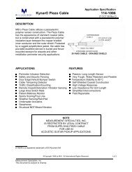
<strong>Roadtrax</strong> <strong>BL</strong> Sensor taped to the road. 12’ long with 100’ passive cable. Chevy<br />
Caprice ≈ 25 mph. 4/25/96. 1V/div vertical scale; 50 msec/div horizontal.<br />
<strong>Roadtrax</strong> <strong>BL</strong> Sensor installed in an asphalt road using epoxy. 200mV/div vertical scale,<br />
200 msec/div horizontal scale. 12’ sensor with 100’ cable. Mid sized car at 35 mph.<br />
<strong>Roadtrax</strong> <strong>BL</strong> <strong>Traffic</strong> <strong>Sensors</strong><br />
Revised October 2001
Read these instructions completely<br />
PRIOR TO INSTALLATION<br />
Approved Installation Epoxies: ECM P5G<br />
Global Resin PU 200, IRD AS475<br />
NOTE: these instructions should<br />
be used for THICKER, high<br />
viscosity material, such as ECM<br />
P5G. If low viscosity material is<br />
used, see notes for the<br />
PU200/260.<br />
1. Carefully mark the slot to be<br />
cut, perpendicular to the flow<br />
of traffic. Ensure that the<br />
sensors are properly<br />
positioned in the lane. Shorter<br />
sensors are positioned to one<br />
side; longer sensors are<br />
typically centered on the lane.<br />
2. Cut a slot 3/4" wide (19mm)�<br />
and 1" deep (25mm). The slot<br />
should be 8” (203 mm) longer<br />
than the sensor. The lead out<br />
should be centered on the slot.<br />
3. It is strongly recommended<br />
that a 3/4" (19mm) wide<br />
diamond blade be used for<br />
cutting the slot, or that blades<br />
be ganged together to get a<br />
single 3/4" (19mm) wide cut.<br />
The slot should be wet cut to<br />
minimize damage to the road<br />
and increase the bonding<br />
strength of the grout.<br />
4. Use high pressure water, or<br />
water and compressed air to<br />
clean ALL foreign matter out of<br />
the slot and 6" (150 mm) on all<br />
sides of the slot. Remove all<br />
excess water and debris with a<br />
vacuum cleaner and/or<br />
sweeping.<br />
5. Carefully dry the slot using<br />
torches, torpedo heaters,<br />
electric heaters, or natural<br />
evaporation. Be very careful<br />
not to burn the asphalt if a<br />
torch is used.<br />
Measurement Specialties Inc, Sensor Products Division,<br />
6. Place a strip of duct tape<br />
along the pavement next to<br />
the slot, leaving 1/8" gap<br />
between edge of slot and<br />
tape. Cover out to about 2"<br />
(50mm) on either side of the<br />
slot for the full length of the<br />
slot.<br />
7. Clean the length of the brass<br />
element of the sensors with<br />
steel wool/emery pad. Bend<br />
the end of the sensor down<br />
30º. Bend the lead<br />
attachment end down 15º and<br />
then back level, forming a lazy<br />
Z.<br />
8. Lay the sensor on the tape<br />
next to the slot. Ensure that<br />
the sensor is straight and flat.<br />
Place the clips on the sensor,<br />
about every 6" (150mm). DO<br />
NOT place the sensor in the<br />
slot at this point, as the clips<br />
are one way and it will be<br />
difficult to remove the sensor<br />
prior to putting in the grout.<br />
9. Block off the ends of the slot<br />
using plumbers putty or<br />
backer rod. Ensure that there<br />
are adequate 'dams' at both<br />
ends so that the<br />
encapsulation material does<br />
not flow out. On the passive<br />
cable end, the dam should be<br />
at least 3" (75mm) past the<br />
lead attachment end.<br />
10. Test the sensor for<br />
capacitance, dissipation factor<br />
and resistance, according to<br />
the directions enclosed.<br />
Record the test results and<br />
the sensor serial number.<br />
This information should be<br />
stored in the counter cabinet<br />
or returned to a data storage<br />
file.<br />
11. Mix the grout according to the<br />
manufactures instructions. Be<br />
sure to pre-mix the resin before<br />
<strong>Roadtrax</strong> <strong>BL</strong> <strong>Traffic</strong> <strong>Sensors</strong><br />
Revised October 2001<br />
combining the two parts since<br />
the aggregate material has a<br />
tendency to settle. Fill the slot<br />
full of the encapsulation material.<br />
Using a trowel, distribute the<br />
encapsulation material along the<br />
sensor, and smooth it out.<br />
12. Ensure that you are wearing<br />
protective plastic or rubber<br />
gloves. Place the sensor in the<br />
slot, with the brass element<br />
about 3/8" (9mm) below the<br />
road surface, and the top of the<br />
brackets about 1/8" (3mm)<br />
below the road surface.<br />
Ensure the ends of the sensors<br />
are pushed down sufficiently.<br />
Smooth out the grout on top of<br />
the sensor, ensuring there is<br />
not a trough on top.<br />
13. Remove the tape on the sides<br />
of the sensor as soon as the<br />
grout starts to cure.<br />
14. Carefully remove the plumber’s<br />
putty or backer rod used to<br />
form the dam at the sensor’s<br />
end.<br />
15. Route the lead in cable through<br />
the home run slot, and cover<br />
with loop sealant or grout. DO<br />
NOT USE HOT TAR.<br />
16. When the encapsulation<br />
material is fully cured, grind the<br />
top of the encapsulation<br />
material flush with the road<br />
using an angle grinder or belt<br />
sander. The profile should be<br />
flat or with a slight 'mound'<br />
(1/16"), provided that there is<br />
no concave portion to the<br />
curve.<br />
17. Clean up the site. When the<br />
encapsulation material is fully<br />
cured, it may be opened to<br />
traffic. Failure to wait for the<br />
encapsulation material to fully<br />
cure may ruin the installation<br />
and cause it to fail prematurely.
• The quality of the road will affect the quality of<br />
the data. The roads should conform to ASTM<br />
specifications for Weigh in Motion<br />
applications.<br />
• Diamond blades should be used on the road<br />
saw. The tolerance for the cut is 11/16" to<br />
13/16". A 3/4" diamond blade is<br />
recommended for cutting the slot. Do not try<br />
to do two independent cuts as it is very<br />
difficult to achieve this level of accuracy.<br />
• Wet cutting is preferred to dry cutting. The dry<br />
cutting forces particles into the sidewalls of<br />
the slot which are very difficult to thoroughly<br />
clean. This residue will diminish the adhesion<br />
of the adhesive to the road, potentially<br />
causing the premature failure of the sensor.<br />
• The passive cable length should not exceed<br />
300' without consulting the manufacture. It is<br />
STRONGLY recommended that the sensors<br />
be ordered with sufficient cable to avoid<br />
splices. If splices are needed, only similar<br />
grade of RG-58 cable should be used, the<br />
splices must be soldered, and an approved<br />
splice kit used to waterproof the splice. MSI<br />
<strong>Sensors</strong> is not responsible for any problems<br />
arising from spicing the cable.<br />
• Disposable gloves must be worn when<br />
working with the clean sensor and<br />
encapsulation material. Appropriate<br />
precautions should be taken, according to the<br />
encapsulation material manufacturer's<br />
instructions. Ensure you read and follow all<br />
safety instructions.<br />
• Adequate traffic control is essential. Do not<br />
put any of your workers at risk.<br />
• Ensure that the sensor is placed in the correct<br />
location on the road. Six foot sensors should<br />
be positioned in a wheel path, NOT in the<br />
center of the lane.<br />
• Care should be taken when mixing the<br />
encapsulation material to minimize the<br />
amount of trapped air in the material. Do not<br />
lift the mixing paddle out of the encapsulation<br />
material while the mixing head is spinning.<br />
Stop the blade and then use a stirring paddle<br />
to scrape the edges of the can.<br />
Measurement Specialties Inc, Sensor Products Division,<br />
Important Notes and Hints:<br />
<strong>Roadtrax</strong> <strong>BL</strong> <strong>Traffic</strong> <strong>Sensors</strong><br />
Revised October 2001<br />
• If heaters are needed to speed the curing<br />
process for the grout, extreme care should be<br />
taken to ensure that the sensors are not<br />
destroyed. The maximum temperature that<br />
the sensors can withstand is 170ºF! An A-<br />
Frame should be constructed out of metal or<br />
plywood, and placed over the sensor. Warm<br />
air from a torpedo heater should be blown in<br />
horizontally into the A-Frame, but NEVER<br />
aimed directly at the sensor. The air<br />
temperature at the sensor location should not<br />
be higher than what can be tolerated by your<br />
hand for 20-30 seconds. If it is hotter than<br />
this, the sensor will loose its piezo activity and<br />
will not function.<br />
• Once the sensor is installed and the grout is<br />
cured, it is recommended that any excessive<br />
grout be ground off, using an angle grinder or<br />
belt sander. The best installation has the<br />
grout flush with the road surface to minimize<br />
any chance of the tires bridging over the<br />
sensor.<br />
• Thin walled plastic tubing may be used to<br />
contain the home run cable. In the unlikely<br />
event that the sensor needs to be replaced,<br />
the passive cable can then be pulled through<br />
the tubing, thereby eliminating the need for<br />
recutting the home run slot.<br />
• Read all of the directions carefully and<br />
completely prior to the installation. Ensure<br />
that you have all of the required equipment<br />
available. If there are any questions on the<br />
installation, call MSI and we will be happy to<br />
'walk' you through the procedures.
Required/recommended tools and materials<br />
• MSI <strong>BL</strong> <strong>Sensors</strong> with installation brackets. <strong>Sensors</strong> should<br />
be ordered with sufficient passive cable to reach the<br />
control cabinet.<br />
• Installation instruction. Read these instructions prior to the<br />
installation. There may need to be some adaptation of<br />
these instructions based on local conditions.<br />
• Sensor support brackets. These are shipped in the box<br />
with the sensors.<br />
• Installation encapsulation. See Recommended materials<br />
under frequently asked questions. Approximately 2 to 1<br />
gallon (1.5 to 3 liters) of material is needed per sensor.<br />
The slot must be carefully cut in order to ensure that it is<br />
not too deep; otherwise excessive material is used. Read,<br />
understand and follow the directions supplied by the<br />
manufacturer of the installation encapsulation. Adhere to<br />
the temperature limits imposed on the material to ensure<br />
adequate drying time is available. Follow all recommended<br />
safety precautions.<br />
• Loop sealant material, to cover the home run cables.<br />
Amount used will depend on the length and width of the<br />
homerun cuts. DO NOT USE HOT TAR..<br />
� Thin wall tubing for homerun cables. Minimum 3/8" (9mm)<br />
ID, flexible tubing. Materials for this tubing are typically<br />
flexible PVC or polyethylene. Sufficient quantity for all<br />
homeruns from the end of the sensors to the cabinet.<br />
� PVC pipe, 2-3" (50-75mm) dia. For use as conduit for any<br />
underground runs from junction boxes to cabinets.<br />
� PVC solvent and joints - as needed for any splices in the<br />
pipes.<br />
• Wet cutting pavement saw. A self-propelled saw of at least<br />
35 hp, fitted with a 14" (350mm) or larger blade. This saw<br />
must be capable of cutting a 3/4" wide x 1" deep (19mm<br />
wide x 19-25mm deep) cut in a single pass.<br />
• Diamond Blades for the saw. Appropriate type for the<br />
pavement being cut. The Piezo sensor needs a cut 11/16"<br />
to 13/16" (19mm 1mm) wide, 1" (25mm) deep slot cut in<br />
the road in a single pass. If a single blade is not available,<br />
multiple blades can be put together to form a dado blade .<br />
A 3/8" (9mm) and a 1/4" (6mm) blade, with a 1/16" (2mm)<br />
spacer between them performs very well. Additional blade<br />
widths are necessary for cutting the slots for the tubing for<br />
the home run cables.<br />
• Large capacity air compressor (at least 150 CFM) with<br />
hose and nozzle - for blowing out the slot and drying the<br />
area after the cut.<br />
• Trenching equipment as required for burying the conduit to<br />
the control cabinet.<br />
• Power washer or high pressure water hose - for washing<br />
out the slot.<br />
• Water - for saw and for washing out the slot<br />
• Broom - Street broom type with stiff bristles for general<br />
cleanup.<br />
• Slow speed electric drill with mixing paddle<br />
! Required Equipment<br />
� Recommended Equipment<br />
Measurement Specialties Inc, Sensor Products Division,<br />
<strong>Roadtrax</strong> <strong>BL</strong> <strong>Traffic</strong> <strong>Sensors</strong><br />
Revised October 2001<br />
• Additional mixing blade if a 2 part loop sealant is<br />
used. There should not be cross contamination of<br />
the grout used for the piezo and the loop sealant<br />
material.<br />
• Wire Brush and/or bristle brush - for cleaning out the<br />
slot after cutting and during washing.<br />
• 3" or 4" (75-100mm) putty knife for use with the grout<br />
• Small pointed trowel for putting the grout into the<br />
slot.<br />
• Wire Strippers. Knife type blade strippers, such as<br />
Ideal Tools Stripmasters should be used due to the<br />
toughness of the HDPE jacket on the sensor<br />
homerun cable.<br />
• Cleaning Materials for hands and equipment. The<br />
citrus hand cleaner works well. Include lots of paper<br />
towels.<br />
• Angle Grinder with appropriate grinding wheel or belt<br />
sander for smoothing out the grout after the<br />
installation.<br />
• Hammer and masonry chisels. May be required for<br />
chipping corners, etc.<br />
• Disposable gloves (rubber dishwashing gloves work<br />
much better than the latex or plastic gloves)<br />
• 2" (50mm) duct tape. Enough for twice the length of<br />
all the sensors. Used to keep excessive grout off the<br />
road next to the slot during the installation.<br />
• Plumbers putty or duct seal to form dams at the end<br />
of the grout<br />
• Straight edge<br />
• Tape measure - at least 20' (6m) long<br />
• Pavement crayons<br />
• Chalk line<br />
• Pavement paint<br />
• 1/8" (3mm) diameter cord or rope for use in laying<br />
out the lines<br />
� Hammer drill and 2" (12mm) concrete bit<br />
• LCR Meter, such as a BK 875A, to check and<br />
measure Capacitance and Resistance of the sensors<br />
before and after installation.<br />
� Oscilloscope. Although not essential, it is the only<br />
instrument that will give a complete verification that<br />
the sensors are fully functioning when the installation<br />
is complete. If reliable power is not available on the<br />
site, a battery operated oscilloscope should be used,<br />
such as the Fluke Scopemeter.<br />
• Generator if electrical power is not available on site.<br />
Verify the electrical load of the tools being used<br />
compared to the capacity of the generator.<br />
• Appropriate traffic control, as required by local<br />
regulations and appropriate safety guidelines<br />
• Safety equipment required for workers. Safety<br />
helmets, safety glasses, reflective vests, etc, as<br />
required.<br />
� Not included in this list are materials required for<br />
inductive loops (if used), control cabinets, junction<br />
boxes, and other off the road work.
Sensor Testing:<br />
Measurement Specialties Inc, Sensor Products Division,<br />
<strong>Roadtrax</strong> <strong>BL</strong> <strong>Traffic</strong> <strong>Sensors</strong><br />
Revised October 2001<br />
The piezoelectric sensors should be tested prior to and after installation. Because of the high costs of installation<br />
compared to the cost of the sensor, it is imperative that the sensors be checked out prior to putting them into the road to<br />
determine if any damage has been done to the sensor during shipping and handling. The following tests should be done<br />
prior to installation:<br />
Equipment needed: LCR meter, such as a BK Instruments 875A or 875B.<br />
1. Capacitance: Measure the capacitance of the sensor with the attached lead in cable. This should be �20%<br />
of the sensor’s data sheet included in the box. The meter should typically be set on a 20nF range. The red<br />
probe should be connected to the center electrode of the cable and the Black probe to the outer braid.<br />
Make sure that you hands are not holding across the two connections.<br />
2. Dissipation Factor: With the capacitance set on the scale indicated above, switch the meter over to<br />
Dissipation Factor. The reading should be less than 0.04.<br />
3. Resistance: Measure the resistance across the sensor. The meter should be set on the 20MΩ setting.<br />
The meter should read in excess of 20MΩ, which is typically displayed with a '1'.<br />
Testing after installation:<br />
Once the sensor is installed and the grout has cured, retest the sensor according to the instructions above. In<br />
addition, it is recommended that an oscilloscope be connected to the sensor and typical waveforms be<br />
collected for a truck and a car. These should then be printed out and saved for permanent records. The output<br />
of the sensor will depend on the type of the installation, sensor length , cable length and epoxies used for the<br />
installation. Typical settings for the scope would be 200 mV/div for a voltage setting and 50 msec/div for a time<br />
setting. The trigger should be set at about 50 mV for a positive going signal.<br />
Sensor Maintenance:<br />
Like any piece of equipment, regular maintenance should be done to the piezoelectric sensors in order to<br />
maintain them for a long service life. The sensors should be inspected on a bi-annual basis, and any cracks in<br />
the road or in the sensor encapsulation should be filled. A low viscosity loop sealant such as Bondo 606 or a<br />
low viscosity epoxy such as Global PX768 should be poured into any cracks, and then squeegeed smooth.<br />
Any loose asphaltic material should be wire brushed away prior to pouring the sealant material in the cracks.<br />
Be carful not to raise the profile of the sensor. The sensor should be tested for capacitance and resistance,<br />
and the results logged in on the data sheet for the sensors.<br />
Quantity of Grout to be Used:<br />
The <strong>BL</strong> sensor is to be installed in 3/4"x1" (19 x 25mm) slot. However, this is difficult to accurately cut,<br />
especially in depth. The formula for the purposes of calculating the amount of encapsulation material to be<br />
used is as follows:<br />
(Length of Sensor {in inches} + 12") *(3/4"1")*2 or (Length of Sensor {in millimeters} + 300mm)<br />
*(19mm*25mm)*2<br />
This gives a 100% safety factor, in case the slot is slightly deep or long and so that the bottom of the bucket is<br />
not being scraped. For planning purposes, 6' (2m) sensors use approximately 2 gallon (1.5 liters)of<br />
encapsulation material and 12' (3.5m) sensors use a gallon (3 liters) of material. There are 230 cubic inches in<br />
a US gallon. Check with the manufacturer of the encapsulation material for the closest package size. If the<br />
resin is sold by weight, divide the weight by the specific gravity (density) to get the volume.
Measurement Specialties Inc, Sensor Products Division,<br />
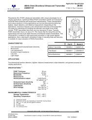
Typical installation layout for a Piezo-Loop-Piezo installation for 6’ Class II sensors<br />
A-A: The passive cable can be put<br />
in a thin wall plastic tube for<br />
additional protection.<br />
<strong>Roadtrax</strong> <strong>BL</strong> <strong>Traffic</strong> <strong>Sensors</strong><br />
Revised October 2001<br />
B-B: Typical cross section<br />
of a <strong>BL</strong> Sensor installation.
Frequently Asked Questions:<br />
Approved Grout for installation<br />
Polyurethane<br />
PU 260 or PU260 (Winter and<br />
Summer versions are available)<br />
There is an updated product<br />
called PU260.<br />
Global Resins Limited<br />
Unit 7<br />
Park Lane Industrial Estate<br />
Corsham, Wilts SN13 9LG<br />
England<br />
Tel: +44 1249 715566<br />
Fax: +44 1249 715533<br />
Available in the USA through:<br />
International <strong>Traffic</strong> Corporation<br />
2402 Spring Ridge Dr, Suite E<br />
Spring Grove, IL 60081<br />
Tel: 815 675 1430<br />
Fax: 815 675 1530<br />
Diamond Saw Blades<br />
Texas Diamond Tools<br />
805 Hilbig Rd<br />
Conroe, TX 77301<br />
Tel: 800 346 0646<br />
Tel: 409 756 0646<br />
Fax: 409 756 0687<br />
14x.750x.250x1", PN# 07147507<br />
BNC Connectors<br />
AMP Incorporated<br />
PO Box 3608<br />
Harrisburg, PA 17111<br />
Tel: 1-800 52AMP52<br />
Also available through Newark<br />
Electric and other Distributors<br />
Part Number 227079-5 (BNC<br />
with Gold center contact)<br />
Part Number 227079-1 (BNC<br />
with Tin-lead center contact)<br />
Hand Crimper - PRO-CRIMPER<br />
Hand Tool 58433-1<br />
Stripping Tool 603995-6<br />
Installation Instructions 408-2798<br />
RF Connector Catalog 82074<br />
Epoxy<br />
None<br />
Measurement Specialties Inc, Sensor Products Division,<br />
Bituthane Pocket Tape for<br />
Temporary installations<br />
Mar Mac Manufacturing Co, Inc<br />
PO Box 278, US Highway One<br />
North<br />
McBee, SC 29101<br />
Tel: 843 335 8211<br />
Toll Free: 800 845 6962<br />
Fax: 843 335 5909<br />
Tape ST0005604 (4" wide with a<br />
2" pocket)<br />
<strong>Roadtrax</strong> <strong>BL</strong> <strong>Traffic</strong> <strong>Sensors</strong><br />
Revised October 2001<br />
Acrylic<br />
ECM P5G<br />
<strong>Electronic</strong> Control Measurement<br />
Inc<br />
PO Box 888<br />
Manor, TX 78653<br />
Tel: 512 272 4346<br />
Fax: 512 272 4966<br />
AS475<br />
International Road Dynamics<br />
702 43 rd Street East<br />
Saskatoon, Saskatchewan<br />
Canada S7K 3T9<br />
Tel: 306 653 6600<br />
Fax: 306 242 5599
Measurement Specialties Inc, Sensor Products Division,<br />
<strong>Roadtrax</strong> <strong>BL</strong> <strong>Traffic</strong> <strong>Sensors</strong><br />
Revised October 2001<br />
Installation hints for the MSI <strong>BL</strong> sensor when using<br />
Global Resin PU 200/PU260 Resin, IRD AS475 and other low viscosity<br />
installation materials.<br />
Layout and mark the location of the sensors on the road. The sensors should be exactly<br />
perpendicular to the flow of traffic. Position the sensor in the left side of the wheelpath, with<br />
the lead attachment of the sensor toward the cabinet. The end of the sensor should be all the<br />
way to the edge of the lane.<br />
Cut a slot for the sensor 3/4" wide ( 1/16") and 1" deep ( 1/4"). The slot should be 8" longer<br />
than the sensor. Wet cut the slot with a diamond blade.<br />
Cut the lead in cable slot centered on the sensor slot. The lead in cable slot should be a<br />
minimum of 2" deep and 1/4" wide. If conduit or tubing is used for the lead in cable, the slot<br />
should be 1/8" wider than the conduit.<br />
Sweep and powerwash with fresh water to clean the slots. Dry them compressed air, natural<br />
evaporation or heaters, depending on weather conditions.<br />
Place a stip of duct tape along the edge of the slot. The duct tape should not overlap into the<br />
slot; it can be up to 1/8" away from the slot.<br />
Remove the sensor from the box. Do not set the sensor on the road. Check to see that the<br />
sensor is straight and flat, with no twists or curls. Straighten the sensor if necessary.<br />
Use an LCR Meter, measure the capacitance, resistance and dissipation factor of the sensor.<br />
Use the 20nF setting for capacitance and dissipation tests and the 20MΩ setting for the<br />
resistance test. Record all results. All capacitance reading should be within � 20% of the<br />
readings on the data sheet provided with each sensor.<br />
Clean the length of the brass element of the sensor with steel wool or an emory pad. Place<br />
the installation brackets on the sensor every 6" ( 1"). Make sure all of the brackets are facing<br />
the same direction.<br />
Slightly bend down the end of the sensor at a 30° angle. Slightly bend down the sensor at the<br />
lead attachment at a 15° angle. Then bend it back level, forming a lazy Z.<br />
Position the sensor in the slot. Start at the end of the sensor and set the clips into the slot.<br />
The end of the sensor should be 3" from the center line/edge of the road.<br />
Press down on the top of the brackets so that they are just below the road surface.<br />
Using a locally made jig or a combination square, press down on the top of the sensor near<br />
the installation bracket so that the top of the sensor is exactly 3/8" below the road surface and<br />
the top of the brackets are 1/8” below the surface of the road.<br />
Use two pieces of backer rod, 2" diameter and about 6" long to seal the home run slot<br />
beyond the location of the lead attachment. The backer rod should be positioned on both<br />
sides of the passive cable, 3" past the end of the lead attachment. Place the passive cable<br />
into the slot, ensuring that it goes all the way to the bottom of the slot. The cable itself should<br />
be positioned in the midpoint of the slot.<br />
If tubing or conduit is used for enclosing the home run cable, it should stop on the far side of<br />
the backer rod.<br />
Visually check the positioning of the sensor. It should be at the same depth along the entire
Measurement Specialties Inc, Sensor Products Division,<br />
<strong>Roadtrax</strong> <strong>BL</strong> <strong>Traffic</strong> <strong>Sensors</strong><br />
Revised October 2001<br />
length. The lead attachment area should be below the road surface at all points, and<br />
centered in the slot. The backer rod should be 3" beyond the lead attachment. The sensor<br />
should not cross any expansion joints or cracks in the pavement.<br />
• Premix the resin for about 2 minutes or until smooth. Use a drywall plaster (mud) mixing<br />
paddle (for example, Grainger part number 4R539, or Home Depot part number 81-001) in a<br />
500 - 600 rpm drill. Make sure the resin is homogeneous prior to adding in the hardener.<br />
• Immediately, pour the resin into the slot. Start at the end and pour a small bead in the<br />
direction of the lead attachment. Go back to the end, and pour another pass, continuing in<br />
this process until the slot is filled completely.<br />
• Lightly trowel the resin smooth. Be very careful to ensure that it is not over worked.<br />
• As soon as the resin starts to cure, remove the tape.<br />
• Allow the resin to fully cure.<br />
• Remove the backer rod used at the lead attachment area.<br />
• Grind off any excess resin off the top of the sensor, using a masonry cup wheel on an angle<br />
grinder or a belt sander. Use the grinder flat - not at an angle where it will make the top of the<br />
grout concave. Do not overgrind.<br />
• Complete the installation by filling the homerun slot with loop sealant material.<br />
• Using a LCR meter, perform the final tests on the sensor, including capacitance, resistance<br />
and dissipation factor. Record all results. All capacitance reading should be within � 20% of<br />
the readings on the data sheet provided with each sensor.<br />
• When the cable is routed all the way into the cabinet, cut the cables to the final length. Again<br />
check capacitance, resistance and dissipation factor and RECORD RESULTS. The<br />
resistance and dissipation factor should be the same; the capacitance will go down at a rate<br />
of 2.7 nF/100' of cable cut off.<br />
• When the lane is opened to traffic, perform a functional test on the sensor using an<br />
oscilloscope. Record results.<br />
Industriestr. 8 8618 Oetwil a/S. Tel: +41 43 844 94 00 Fax: +41 43 844 94 01 ELECTRONIC HARDWARE <strong>AG</strong><br />
http://www.ehag.ch E-Mail: info@ehag.ch