SEPIC Design Inductor Application Guide - Cooper Industries
SEPIC Design Inductor Application Guide - Cooper Industries
SEPIC Design Inductor Application Guide - Cooper Industries

Create successful ePaper yourself
Turn your PDF publications into a flip-book with our unique Google optimized e-Paper software.
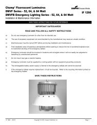
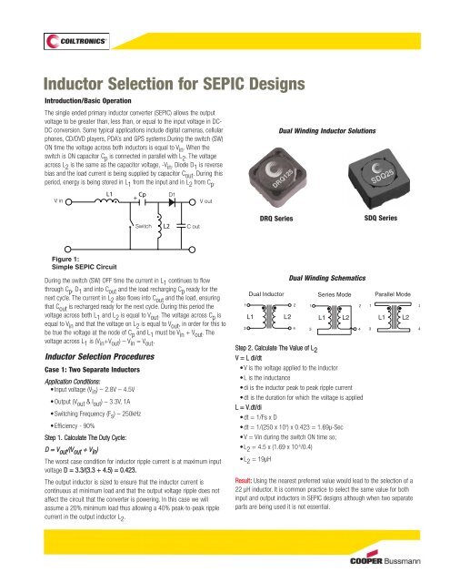
<strong>Inductor</strong> Selection for <strong>SEPIC</strong> <strong>Design</strong>s<br />
Introduction/Basic Operation<br />
The single ended primary inductor converter (<strong>SEPIC</strong>) allows the output<br />
voltage to be greater than, less than, or equal to the input voltage in DC-<br />
DC conversion. Some typical applications include digital cameras, cellular<br />
phones, CD/DVD players, PDA’s and GPS systems.During the switch (SW)<br />
ON time the voltage across both inductors is equal to Vin . When the<br />
switch is ON capacitor Cp is connected in parallel with L2 . The voltage<br />
across L2 is the same as the capacitor voltage, -Vin . Diode D1 is reverse<br />
bias and the load current is being supplied by capacitor Cout . During this<br />
period, energy is being stored in L1 from the input and in L2 from Cp .<br />
V in<br />
During the switch (SW) OFF time the current in L 1 continues to flow<br />
through C p ,D 1 and into C out and the load recharging C p ready for the<br />
next cycle. The current in L 2 also flows into C out and the load, ensuring<br />
that C out is recharged ready for the next cycle. During this period the<br />
voltage across both L 1 and L 2 is equal to V out . The voltage across C p is<br />
equal to V in and that the voltage on L 2 is equal to V out , in order for this to<br />
be true the voltage at the node of C p and L 1 must be V in + V out . The<br />
voltage across L 1 is (V in +V out ) – V in = V out .<br />
<strong>Inductor</strong> Selection Procedures<br />
Case 1: Two Separate <strong>Inductor</strong>s<br />
AApppplliiccaattiioonn CCoonnddiittiioonnss::<br />
Input voltage (Vin ) – 2.8V – 4.5V<br />
Output (Vout & Iout ) – 3.3V, 1A<br />
Switching Frequency (Fs ) – 250kHz<br />
Efficiency - 90%<br />
Step 1. Calculate The Duty Cycle:<br />
DD == VV oouutt //((VV oouutt ++ VV iinn ))<br />
L1<br />
Figure 1:<br />
Simple <strong>SEPIC</strong> Circuit<br />
+ Cp<br />
Switch L2 C out<br />
V out<br />
The worst case condition for inductor ripple current is at maximum input<br />
voltage D = 3.3/(3.3 + 4.5) = 0.423.<br />
The output inductor is sized to ensure that the inductor current is<br />
continuous at minimum load and that the output voltage ripple does not<br />
affect the circuit that the converter is powering. In this case we will<br />
assume a 20% minimum load thus allowing a 40% peak-to-peak ripple<br />
current in the output inductor L2 .<br />
D1<br />
1<br />
3<br />
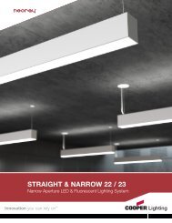
DRQ Series<br />
Dual <strong>Inductor</strong><br />
L1 L2<br />
Dual Winding <strong>Inductor</strong> Solutions<br />
Dual Winding Schematics<br />
2<br />
4<br />
Series Mode<br />
L1<br />
Step 2. Calculate The Value of L2 V = L di/dt<br />
•V is the voltage applied to the inductor<br />
L is the inductance<br />
di is the inductor peak to peak ripple current<br />
dt is the duration for which the voltage is applied<br />
L = V.dt/di<br />
dt = 1/Fs x D<br />
dt = 1/(250 x 103 ) x 0.423 = 1.69µ-Sec<br />
V = Vin during the switch ON time so;<br />
L2 = 4.5 x (1.69 x 10-6 /0.4)<br />
L2 = 19µH<br />
1<br />
3<br />
SDQ Series<br />
Result: Using the nearest preferred value would lead to the selection of a<br />
22 µH inductor. It is common practice to select the same value for both<br />
input and output inductors in <strong>SEPIC</strong> designs although when two separate<br />
parts are being used it is not essential.<br />
L2<br />
Parallel Mode<br />
2 1 2<br />
L1<br />
L2<br />
4 3 4
SDQ Series DRQ Series<br />
Step 3. Calculate RMS and Peak Current Ratings for Both <strong>Inductor</strong>s<br />
Input <strong>Inductor</strong> L1 Irms = (Vout x Iout )/(Vin (min) * efficiency)<br />
Irms = (3.3 x 1)/(2.8 x 0.9) = 1.31A<br />
Ipeak = Irms + (0.5 x Iripple )<br />
Iripple = (V.dt)/L<br />
Iripple = (2.8 x 2.2 x 10-6 )/22 x 10-6 = 0.28A<br />
Ipeak = 1.31 + 0.14 =1.45A<br />
Although worst case ripple current is at maximum input voltage the peak<br />
current is normally highest at the minimum input voltage.<br />
Result: 22µH, 1.31A rms and 1.45A pk rated inductor is required. For<br />
example the Coiltronics ® DR73-220 which has 1.62A rm s and 1.67A pk<br />
current ratings.<br />
OOuuttppuutt IInndduuccttoorr LL 22<br />
Irms = Iout = 1A<br />
Iripple = (4.5 x 1.69 x 10-6 )/22 x 10-6 = 0.346A<br />
Ipeak = 1 + 0.173 = 1.173A<br />
Result: A 22µH, 1A rms and 1.173A pk rated inductor is required, which for<br />
simplicity could be the same DR73-220 inductor used for L 1<br />
PDAs<br />
Servers<br />
Typical <strong>Application</strong>s Using <strong>Inductor</strong>s for <strong>SEPIC</strong> <strong>Design</strong>s<br />
Digital Cameras<br />
Case 2: Coupled <strong>Inductor</strong><br />
Step 1. Perform Step 1 and The Irms Portion of Step 3 from the TTwwoo<br />
SSeeppaarraattee IInndduuccttoorr Selection<br />
The application information listed for the two inductor selection will be<br />
used.<br />
Step 2. Calculate The Inductance Value<br />
LL == VV..ddtt//ddii<br />
From our earlier example the output ripple current needs to be 0.4Apk-pk ,<br />
so now we calculate for 0.8A as the ripple current is split between the two<br />
windings<br />
LL == 44..55 xx ((11..6699 xx 1100 --66 //00..88)) == 99..55µµHH<br />
A coupled inductor has the current flowing in one inductor and if the<br />
two windings are closely coupled the ripple current will be split equally<br />
between them.<br />
Using a coupled inductor reduces the required inductance by half.<br />
Since the two winding are on the same core they must be the same<br />
inductance value.<br />
Step 3. Calculate the Peak Current<br />
Continuing with the example using an inductance value of 10µH we now<br />
need to calculate the worst case peak current requirement. The RMS<br />
current in each winding is already known.<br />
Input inductor RMS current = 1.31A<br />
Output inductor RMS current = 1A<br />
Ipeak = Iin + Iout + (0.5 x Iripple )<br />
I ripple = (2.8 x 2.2 x 10 -6 )/10 x 10 -6 = 0.62A<br />
I peak = 1.31 + 1 + 0.31 = 2.62A @ minimum input voltage<br />
Result: A 10µH coupled inductor with 2.31Arms and 2.62Apk current ratings<br />
is required, for example the Coiltronics ® DRQ74-100.<br />
Using a coupled inductor takes up less space on the PCB and tends to be<br />
lower cost than two separate inductors. It also offers the option to have<br />
most of the inductor ripple current flow in either the input or the output. By<br />
doing this the need for input filtering can be minimized or the output ripple<br />
voltage can be reduced to very low levels when supplying sensitive circuits.<br />
Mobile Phones<br />
Laptop Computers Display Backlighting Flat-Screen Televisions
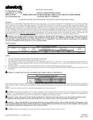
DRQ Series Parallel Ratings Series Ratings<br />
Part Number Rated OCL I rms I sat DCR Ω OCL I rms I sat DCR Ω<br />
Inductance +/-20% Amps Amps Typ. +/-20% Amps Amps Typ.<br />
(μH) (μH) Peak (μH) Peak<br />
DRQ73-1R0-R 1.00 0.992 5.25 7.97 0.0103 3.968 2.63 3.99 0.0411<br />
DRQ73-2R2-R 2.20 2.070 4.11 5.52 0.0167 8.280 2.06 2.76 0.0669<br />
DRQ73-3R3-R 3.30 3.540 3.31 4.22 0.0259 14.16 1.66 2.11 0.1035<br />
DRQ73-4R7-R 4.70 4.422 3.09 3.78 0.0297 17.69 1.55 1.89 0.1188<br />
DRQ73-100-R 10.0 10.30 2.08 2.47 0.0656 41.20 1.04 1.24 0.2623<br />
DRQ73-220-R 22.0 22.65 1.62 1.67 0.107 90.60 0.811 0.83 0.429<br />
DRQ73-330-R 33.0 34.41 1.31 1.35 0.166 137.6 0.653 0.68 0.665<br />
DRQ73-470-R 47.0 48.62 1.08 1.14 0.241 194.5 0.542 0.57 0.965<br />
DRQ73-680-R 68.0 68.91 0.89 0.96 0.358 275.6 0.444 0.48 1.43<br />
DRQ73-101-R 100 101.4 0.73 0.79 0.527 405.6 0.367 0.39 2.11<br />
DRQ73-221-R 220 223.3 0.52 0.53 1.05 893.2 0.260 0.27 4.20<br />
DRQ73-331-R 330 325.5 0.42 0.44 1.59 1302 0.211 0.22 6.36<br />
DRQ73-471-R 470 465.8 0.35 0.37 2.36 1863 0.173 0.18 9.44<br />
DRQ125-1R0-R 1.00 0.894 15.0 23.6 0.0024 3.576 7.51 11.8 0.0096<br />
DRQ125-1R5-R 1.50 1.478 13.8 18.3 0.0029 5.912 6.89 9.15 0.0114<br />
DRQ125-2R2-R 2.20 2.208 10.9 15.0 0.0045 8.832 5.46 7.50 0.0182<br />
DRQ125-3R3-R 3.30 3.084 9.26 12.7 0.0063 12.34 4.63 6.35 0.0253<br />
DRQ125-4R7-R 4.70 5.274 7.18 9.71 0.0105 21.10 3.59 4.86 0.0420<br />
DRQ125-100-R 10.0 9.654 5.35 7.17 0.0189 38.62 2.67 3.59 0.0757<br />
DRQ125-220-R 22.0 22.36 3.70 4.71 0.0396 89.44 1.84 2.36 0.159<br />
DRQ125-330-R 33.0 33.74 3.28 3.84 0.0505 135.0 1.64 1.92 0.203<br />
DRQ125-470-R 47.0 47.47 2.71 3.24 0.0740 189.9 1.35 1.62 0.297<br />
DRQ125-680-R 68.0 67.91 2.22 2.70 0.101 271.6 1.11 1.35 0.440<br />
DRQ125-101-R 100 102.7 1.78 2.20 0.170 410.8 0.892 1.10 0.682<br />
DRQ125-221-R 220 216.8 1.19 1.51 0.384 867.2 0.594 0.755 1.54<br />
DRQ125-331-R 330 332.6 1.06 1.22 0.482 1330 0.530 0.610 1.93<br />
DRQ125-471-R 470 473.1 0.87 1.02 0.718 1892 0.434 0.510 2.87<br />
NNoottee:: DRQ 74 and DRQ127 not shown. For full product information and a listing of all available inductor values,<br />
see http://www.cooperbussmann.com/datasheets/elx, Data Sheet number 4311.<br />
DRQ73 Dimensions - mm<br />
Top View<br />
1 DRQ73 4<br />
2<br />
###<br />
3<br />
1<br />
2<br />
1<br />
3<br />
0.60<br />
2<br />
DRQ125 Dimensions - mm<br />
Top View<br />
DRQ125<br />
###<br />
wwllyy R<br />
Schematic<br />
Dual <strong>Inductor</strong><br />
L1 L2<br />
4<br />
3<br />
2<br />
4<br />
1<br />
2.00 2<br />
1<br />
3<br />
1<br />
Bottom View<br />
6.1<br />
0.73<br />
2.05<br />
10.0<br />
Series Mode<br />
L1<br />
3<br />
4<br />
0.80<br />
3<br />
4<br />
7.6<br />
Max.<br />
12.5<br />
Max<br />
Side View<br />
3.55 Max<br />
7.6<br />
Max.<br />
Bottom View Side View<br />
L2<br />
Parallel Mode<br />
2 1 2<br />
L1<br />
L2<br />
4 3 4<br />
6.00 Max<br />
12.5<br />
Max<br />
Recommended Pad Layout<br />
1.73<br />
1. 00<br />
0.40<br />
1.<br />
00<br />
0.40<br />
1.73<br />
2.50<br />
1<br />
4 1<br />
4<br />
2 3<br />
2 3<br />
7.9<br />
Dual <strong>Inductor</strong> Mode<br />
1<br />
2<br />
3.85<br />
0.50<br />
7.9<br />
Series Mode<br />
Recommended Pad Layout<br />
4<br />
3.85<br />
13.80<br />
13.80<br />
Dual <strong>Inductor</strong> Mode Series Mode<br />
1<br />
2.50<br />
3 2<br />
0.50<br />
4<br />
3<br />
DRQ Series
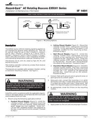
SDQ Series Parallel Ratings Series Ratings<br />
Part Number Rated Part OCL I rms I sat DCR Ω OCL I rms I sat DCR Ω<br />
Inductance Marking +/-20% Amps Amps Typ. +/-20% Amps Amps Typ.<br />
(μH) (μH) (μH)<br />
SDQ12-1R0-R 1 B 0.81 2.49 3.38 0.0403 3.24 1.25 1.69 0.1611<br />
SDQ12-2R2-R 2.2 D 2.25 1.60 2.03 0.0977 9.00 0.800 1.01 0.3908<br />
SDQ12-3R3-R 3.3 E 3.61 1.28 1.60 0.1527 14.44 0.640 0.800 0.6106<br />
SDQ12-4R7-R 4.7 F 4.41 1.12 1.45 0.1990 17.64 0.560 0.724 0.7959<br />
SDQ12-100-R 10 J 9.61 0.831 0.981 0.3620 38.44 0.416 0.490 1.45<br />
SDQ12-220-R 22 L 22.09 0.548 0.647 0.8332 88.36 0.274 0.323 3.33<br />
SDQ12-330-R 33 M 32.49 0.439 0.533 1.29 130.0 0.220 0.267 5.18<br />
SDQ12-470-R 47 N 47.61 0.401 0.441 1.55 190.4 0.201 0.220 6.21<br />
SDQ25-1R0-R 1 C 0.97 3.15 4.09 0.0252 3.87 1.58 2.05 0.1007<br />
SDQ25-2R2-R 2.2 E 2.31 2.67 2.65 0.0351 9.25 1.34 1.32 0.1402<br />
SDQ25-3R3-R 3.3 F 2.89 2.50 2.37 0.0399 11.55 1.25 1.18 0.1595<br />
SDQ25-4R7-R 4.7 G 5 1.96 1.80 0.0653 20.00 0.98 0.900 0.2612<br />
SDQ25-100-R 10 K 9.8 1.53 1.29 0.1068 39.20 0.765 0.643 0.4273<br />
SDQ25-220-R 22 M 22.47 1.01 0.849 0.2431 89.89 0.507 0.425 0.9724<br />
SDQ25-330-R 33 N 33.8 0.812 0.692 0.3795 135.2 0.406 0.346 1.52<br />
SDQ25-470-R 47 O 47.43 0.749 0.584 0.4461 189.7 0.374 0.292 1.78<br />
SDQ25-680-R 68 P 69.19 0.603 0.484 0.6865 276.8 0.302 0.242 2.75<br />
SDQ25-101-R 100 R 98.57 0.499 0.405 1.00 394.3 0.249 0.203 4.02<br />
SDQ25-221-R 220 T 223.1 0.326 0.269 2.36 892.4 0.163 0.135 9.42<br />
SDQ25-331-R 330 U 329.7 0.292 0.222 2.93 1318.7 0.146 0.111 11.71<br />
SDQ25-471-R 470 V 472.4 0.243 0.185 4.25 1889.6 0.121 0.093 16.99<br />
NNoottee: For full product information and a listing of all available inductor values, see http://www.cooperbussmann.com/datasheets/elx,<br />
Data Sheet number SDQ Series.<br />
SDQ12 and SDQ25 Dimensions - mm<br />
Pin #1 identifier<br />
Part marking<br />
(Note A)<br />
1<br />
2<br />
Top View Side View<br />
5.2<br />
Max<br />
© 2008 <strong>Cooper</strong> Bussmann<br />
St. Louis, MO 63178<br />
636-394-2877<br />
www.cooperbussmann.com<br />
4<br />
3<br />
5.2<br />
Max<br />
SDQ12 = 1.2mm Max<br />
SDQ25 = 2.5mm Max<br />
1.5 typ ref<br />
3<br />
1.5 Typ.<br />
Ref. 4<br />
Reorder # 4030 1008 PDF Only<br />
2<br />
1<br />
Bottom View<br />
1.02<br />
Recommended Pad Layout<br />
2 PAD LAYOUT<br />
2.575<br />
5.15<br />
5.95<br />
2.975<br />
2.975<br />
R2.250<br />
4 PAD LAYOUT<br />
1 4<br />
5.950<br />
2 3 2.975<br />
5.950<br />
R2.250<br />
2.975<br />
1 4 1<br />
4 1<br />
4<br />
2<br />
TRANSFORMER<br />
3<br />
Schematic<br />
2<br />
PARALLEL<br />
3<br />
2<br />
3<br />
SERIES<br />
SDQ Series<br />
The <strong>Cooper</strong> Bussmann Coiltronics ® brand of magnetics specializes in standard and custom solutions, offering the latest in state-of-the-art<br />
low-profile high power density magnetic components. We remain at the forefront of innovation and new technology to deliver the optimal mix of<br />
packaging, high efficiency and unbeatable reliability. Our designs utilize high frequency, low core loss materials, and new and custom core shapes<br />
in combination with innovative construction and packaging to provide designers with the highest performance parts available on the market. The<br />
Coiltronics Brand product line of power magnetics continually expands to satisfy shifts in technology and related market needs. Standard Product<br />
Categories include:<br />
Shielded Drum <strong>Inductor</strong>s Unshielded Drum <strong>Inductor</strong>s High Current <strong>Inductor</strong>s<br />
Toroidal <strong>Inductor</strong>s Specialty Magnetics Custom Magnetics<br />
Please visit http://www.cooperbussmann.com/datasheets/elx to see data sheets on the wide variety of inductor solutions we have to offer.<br />
For techncial inquiries e-mail <strong>Inductor</strong>Tech@cooperindustries.com.<br />
Order samples online - www.cooperbussmann.com