freePORT PAS 400 - Georg Neumann GmbH
freePORT PAS 400 - Georg Neumann GmbH
freePORT PAS 400 - Georg Neumann GmbH

Create successful ePaper yourself
Turn your PDF publications into a flip-book with our unique Google optimized e-Paper software.
Portable active loudspeaker<br />
Installation & Operation Manual<br />
<strong>freePORT</strong><br />
<strong>PAS</strong> <strong>400</strong><br />
058-E0146<br />
Version 060328
Content<br />
Safety Instructions ................................................................................................................................................. 3<br />
1 Installation & Set-up ........................................................................................................................................ 6<br />
1.1 Safety Precautions ............................................................................................................................................... 6<br />
1.2 Deliverables ........................................................................................................................................................... 6<br />
1.3 Operating Conditions ........................................................................................................................................... 6<br />
1.4 Set Up ...................................................................................................................................................................... 7<br />
1.5 Power / Mains Connection (1) ........................................................................................................................... 7<br />
1.6 GROUND LIFT Switch (2) ...................................................................................................................................... 8<br />
1.7 Fuses (3) and (4) .................................................................................................................................................. 8<br />
1.8 Powering with a 12-16 Volt DC External or Auto Battery (5) ..................................................................... 8<br />
1.9 Power Switch (6) .................................................................................................................................................. 8<br />
1.10 Power On Indicator (7) ...................................................................................................................................... 9<br />
1.11 Battery Charging Circuit & Loading Indicator (8) ........................................................................................ 9<br />
1.12 Deep Discharge Cut-Off Circuit ...................................................................................................................... 10<br />
1.13 Connecting Signal Sources ............................................................................................................................. 10<br />
1.14 Audio and DC Outputs ..................................................................................................................................... 12<br />
1.15 PDD 63 Delay Unit ............................................................................................................................................ 12<br />
2 Operation ......................................................................................................................................................... 13<br />
2.1 Dynamic Microphones - Distant-Miking Set-up ............................................................................................ 13<br />
2.2 Dynamic Microphones - Close-Miking Set-up ................................................................................................ 13<br />
2.3 Electret-Condenser Microphones - Distant-Miking Set-up ......................................................................... 13<br />
2.4 Electret-Condenser Microphones - Close-Miking Set-up ............................................................................. 13<br />
2.5 Mixing Console or Line-Level Inputs ............................................................................................................... 13<br />
2.6 Recording from the <strong>PAS</strong> <strong>400</strong> ............................................................................................................................ 13<br />
2.7 TONE Controls ...................................................................................................................................................... 14<br />
2.8 Rechargeable Battery -Description ................................................................................................................. 14<br />
2.9 Battery Replacement and Disposal ................................................................................................................. 14<br />
3 Troubleshooting ............................................................................................................................................. 15<br />
4 Performance Curves ....................................................................................................................................... 16<br />
5 Product Specifications ................................................................................................................................... 17<br />
6 Warranty Information ................................................................................................................................... 21<br />
2 <strong>freePORT</strong> <strong>PAS</strong> <strong>400</strong> Version 060328
Warning!<br />
Warning!<br />
Safety Instructions<br />
It is absolutely essential that you read these safety instructions carefully before<br />
connecting and using this K+H product. Your safety depends on it. Furthermore,<br />
failure to follow these instructions voids the warranty.<br />
To ensure safe operation for years to come, keep these instructions in a safe place for<br />
future reference. K+H has manufactured this product in accordance with IEC 92 (SEC)<br />
39 standards, then tested and delivered it in safe operating condition. To maintain it<br />
in this condition, you must:<br />
� observe all safety instructions<br />
� use the product only as described herein<br />
� have any maintenance, repairs, or modifications performed only by K+H or other<br />
authorized personnel<br />
� ensure that the room in which you use this product is wired in accordance with the<br />
local electrical code<br />
When the interior of the cabinet is exposed, touching some parts can lead to an electric<br />
shock.<br />
If you need to gain access to the interior electronics of the unit, always disconnect the unit<br />
from any and all power sources first.<br />
Any repairs, maintenance, or other service of the unit when its interior compartment is<br />
exposed may only be performed safely (in accordance with VBG 4) by authorized<br />
technicians familiar with all the risks involved. Even in an unplugged state, a fully charged<br />
capacitor in the unit can zap the unsuspecting.<br />
Loudspeaker output jacks labelled with the IEC 417/5036 emblem (Fig. A) may be carrying<br />
dangerously high voltages. If your unit has this emblem, ensure that any connections to be<br />
made between these jacks and the speakers themselves are made before powering up the<br />
unit, and are done so only with manufacturer-approved interconnecting cables.<br />
If you need to replace any fuses, ensure that the replacements are of exactly the same type,<br />
value and voltage as the originals, as spelled out in the technical specifications at the rear<br />
of this manual.<br />
Do not use "repaired" fuses.<br />
If you do not have fuses of the specified size, type and value, do not hot-wire the contacts<br />
in the holder by short-circuiting them.<br />
Certain areas of the cabinet, cover, and rear panel can achieve extreme temperatures and<br />
are therefore marked with a "HOT" label (Fig. B). Refrain from touching any heat sink or<br />
ventilation grille.<br />
High volume levels are known to cause permanent - i.e. irreversible - hearing damage,<br />
especially when listened to without sufficient breaks. The higher the levels, the more<br />
frequent and extended must be the breaks. Avoid standing too close to loudspeakers that<br />
are being driven at high levels. If you must be exposed to high sound pressure levels over<br />
an extended period of time, use hearing protection.<br />
Mains Connection: � This unit is designed for continuous operation.<br />
� Ensure that the operating voltage of the unit matches that of the local mains<br />
current (AC line voltage).<br />
<strong>freePORT</strong> <strong>PAS</strong> <strong>400</strong> Version 060328 3
4 <strong>freePORT</strong> <strong>PAS</strong> <strong>400</strong> Version 060328<br />
� Always check before connecting the power cable to the mains socket that the power switch<br />
on the unit itself is set to off ("O").<br />
� Use the power cable or power supply that came with the unit to connect to the mains<br />
socket (wall outlet).<br />
� Power supply: a damaged power cable may not be repaired. Use a new cable.<br />
� Avoid plugging the mains cable into a power strip that already has several other powerconsuming<br />
devices connected to it.<br />
� Avoid using extension cables. The unit must be connected to a mains socket close to it, and<br />
that socket should be freely accessible.<br />
Installation: � This product may only be placed on a stable, clean, horizontal surface.<br />
� Do not expose this product to vibration.<br />
� Do not operate this product anywhere near water or other liquids. Do not use it near a sink,<br />
swimming pool, bathtub, or in any damp room or area. Electrical shocks carried through<br />
water can kill. Do not place any beverages whatsoever on or near this product, as liquids<br />
can kill electronic components.<br />
� Ensure sufficient ventilation around the product to allow for adequate heat dissipation,<br />
especially near the rear panel and the sides of the cabinet (minimum of 8 inches from the<br />
nearest wall). The unit may only be installed in a rack if measures are taken to ensure<br />
sufficient ventilation and if the mounting instructions of the manufacturer are followed. Do<br />
not block or cover any heat sink, fan, or vent.<br />
� Do not place the product where it will be in the path of direct sunlight, and keep it a safe<br />
distance away from radiators and other heaters of any kind.<br />
� If you bring this product from a cold environment into a warm one (such as from a vehicle<br />
into a studio), it is quite possible that condensation will form inside the cabinet. Please<br />
allow the unit sufficient time for acclimation to room temperature (minimum thirty<br />
minutes) before connecting and powering up.<br />
� To avoid accidents, do not use any accessory equipment with this product that is not<br />
approved by the manufacturer, particularly mounting accessories.<br />
� Do not place this unit on any unstable platform, cart, stand or table. If the unit falls, it can<br />
cause bodily injury to persons, or can be damaged itself.<br />
� To protect this product from lightning damage during a thunderstorm or from power<br />
surges during an extended absence, disconnect the power cable from the wall outlet.
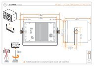
Rear Panel View<br />
<strong>freePORT</strong> <strong>PAS</strong> <strong>400</strong><br />
Numbered items correspond to explanations in the text<br />
<strong>freePORT</strong> <strong>PAS</strong> <strong>400</strong> Version 060328 5
6 <strong>freePORT</strong> <strong>PAS</strong> <strong>400</strong> Version 060328<br />
1 Installation & Set-up<br />
1.1 Safety Precautions<br />
Note!<br />
Please read and follow all of the safety precautions in this manual! It is absolutely essential<br />
that you read these safety instructions carefully before connecting and using this product.<br />
Your safety depends on it. Furthermore, failure to follow these instructions voids the<br />
warranty.<br />
To ensure safe operation for many years, keep these instructions in a safe place for future<br />
reference. K+H has manufactured this product in accordance with IEC 92 (SEC) 39 standards,<br />
then tested and delivered it in a safe operating condition. To maintain it in this condition, you<br />
must:<br />
� observe all safety instructions,<br />
� use the product only as described herein<br />
� have any maintenance, repairs, or modifications performed only by K+H or its authorized<br />
agents<br />
� ensure that the room in which the product is used is wired in accordance with local<br />
electrical codes<br />
If the loudspeaker will be installed in an area where people could go underneath it, then it<br />
should be secured with an additional safety cable, which can be attached to the carrying<br />
handles!<br />
1.2 Deliverables<br />
� 1 <strong>freePORT</strong> <strong>PAS</strong> <strong>400</strong> active PA loudspeaker system<br />
� 1 power supply cable<br />
� 1 Installation & Operation Manual<br />
1.3 Operating Conditions<br />
The temperature limits for the <strong>freePORT</strong> <strong>PAS</strong> <strong>400</strong> active PA loudspeaker system are as<br />
follows:<br />
Operating Temperature:<br />
+14 to +104 °F (-10 to +40 °C)<br />
Storage or Transportation Temperature:<br />
+5 to +104 °F (-15 to +40 °C)<br />
If the temperature of the loudspeaker falls below 5 °F (-15 °C) at any time, the rechargeable<br />
battery may be permanently damaged.<br />
The <strong>freePORT</strong> <strong>PAS</strong> <strong>400</strong> will operate in any position and under a variety of conditions. It is,<br />
however, not watertight and should only be installed or operated in dry conditions. Areas<br />
with excessive moisture, considerable dust or aggressive chemicals should also be avoided.<br />
The <strong>freePORT</strong> <strong>PAS</strong> <strong>400</strong> is not for outdoor installations. Temporary outdoor usage is possible,<br />
but only within the temperature limits and in no situations where water can directly come in<br />
contact with the unit. For operation under rainy conditions, the LRH/S Rain Hood accessory<br />
must be used.<br />
The coated loudspeaker cones can handle temporary exposure to fog but in no case can they<br />
tolerate any dew or condensation.
Attention!<br />
If a small amount of moisture or dew has formed on the cabinet or the back panel, e.g. after<br />
transportation or storage, carefully wipe off all of the moisture with a clean, soft cloth and<br />
allow the unit to acclimate in a warm, dry environment for at least two hours before applying<br />
power to the unit or operating it.<br />
1.4 Set Up<br />
1.4.1 Tripod or Pole Mounting<br />
The <strong>freePORT</strong> <strong>PAS</strong> <strong>400</strong> enclosure is fitted, on the bottom, with a standard 35 mm mounting<br />
flange for tripod or pole mounting. It can also be mounted to the LST 60 spiked pole for<br />
outdoor use on uneven ground.<br />
With the LH 33 tilt connector the tilt angle can be adjusted from 0° (perpendicular) to 15°.<br />
For maximum tilt-angle adjustability, the LH 26 fork mounting bracket can be attached to<br />
the <strong>PAS</strong> <strong>400</strong> with 2 x M8 knurled thumbscrews and then combined with an LH 28 tripod<br />
stand adapter to mount it to a tripod. The speaker can then be rotated and tilted to the<br />
optimum angle for the listeners.<br />
1.4.2 Wall or Ceiling Mounting<br />
For hang-mounting, the top of the enclosure has two M8 threaded attachment points (115<br />
mm spacing) for attaching an LH 29 TV spigot for mounting to cross beams or light stands.<br />
For wall mounting with maximum adjustability, the speaker can be attached, via the 35 mm<br />
mounting flange on the bottom, to an LH 120 wall mount bracket. The speaker can then be<br />
rotated and tilted (10 - 25°) to the optimum angle for the listeners.<br />
1.4.3 Positioning & Alignment<br />
Position the loudspeakers so that they:<br />
� will not be directly aimed at any open microphones<br />
� will be as far away from the microphones as possible - especially important with sensitive<br />
or long-distance microphones<br />
� will be at the front of the stage or more forward than the microphones (in relation to the<br />
listeners)<br />
1.5 Power / Mains Connection (1)<br />
The <strong>freePORT</strong> <strong>PAS</strong> <strong>400</strong> is available in the following AC mains voltage configurations:<br />
� 230 Volt AC / 50 Hz<br />
(supplied with a German Schuko mains cable connector)<br />
� 120 Volt AC / 60 HZ<br />
(supplied with a USA 3-prong mains cable connector)<br />
� 100 Volt AC / 50-60 Hz<br />
(supplied with a USA 3-prong mains cable connector)<br />
Before connecting to the mains power supply:<br />
� Verify that each <strong>PAS</strong> <strong>400</strong> system matches the mains voltage at the site!<br />
� Do not disconnect any part of the ground connection! When powered from an AC mains<br />
supply, the system must only be operated with a proper ground connection!<br />
The (supplied) mains cable connector may not match the AC outlet type in some countries.<br />
Only a qualified electrician should change the AC connector and the proper groundconnection<br />
must be made.<br />
<strong>freePORT</strong> <strong>PAS</strong> <strong>400</strong> Version 060328 7
8 <strong>freePORT</strong> <strong>PAS</strong> <strong>400</strong> Version 060328<br />
1.6 GROUND LIFT Switch (2)<br />
The signal GROUND LIFT switch should be set to the GROUND position. If the <strong>PAS</strong> <strong>400</strong> hums<br />
when connected to other equipment, setting the switch to the GROUND LIFTED position may<br />
reduce or eliminate the hum.<br />
1.7 Fuses (3) and (4)<br />
Disconnect the <strong>PAS</strong> <strong>400</strong> from any external power supply (mains or battery) before changing<br />
or inspecting fuses.<br />
Only the following fuse types can be used<br />
1A Slo-Blo for 230 Volt AC / 50 Hz models<br />
2A Slo-Blo for 120 Volt AC / 60 Hz<br />
2A Slo-Blo for 100 Volt AC / 50-60 Hz<br />
6.3A Slo-Blo for the rechargeable battery<br />
1.8 Powering with a 12-16 Volt DC External or Auto Battery (5)<br />
The "EXT BATTTERY 12 - 16 VDC" socket is accessible by removing the sealing cap.<br />
A plug-in connector for this is socket available. Please note the correct polarity (labelled as<br />
"+" and "-" by the socket). Incorrect polarity will not cause damage, but the internal battery<br />
will then power the <strong>PAS</strong> <strong>400</strong>.<br />
1.9 Power Switch (6)<br />
The power switch has three positions:<br />
Position 0 Loudspeaker system is Off<br />
Battery will charge (if connected<br />
to a power supply)<br />
Position I Loudspeaker system is On<br />
Wireless receiver is On<br />
Battery will charge (if connected<br />
to a power supply)<br />
Position II Loudspeaker system is On<br />
Wireless receiver is Off<br />
Battery will charge (if connected<br />
to a power supply)<br />
When the system is switched On (to Position I or Position II), there is an automatic 3-second<br />
delay before it is operational.<br />
When the (optional) built-in wireless receiver is not being used, set the Power Switch to<br />
Position II to conserve battery power and to get the longest run-time per charge.<br />
When switching from Position I to Position II (or visa versa), first switch to Position 0 and wait<br />
5 seconds before switching to the next position, otherwise, the Deep Discharge Cut-Off Circuit<br />
may be activated (if activated, switch to Position 0 and wait 30 seconds before switching to<br />
Position I or II.).
If AC mains power is interrupted, the system will automatically switch over to battery power.<br />
Remote On / Off switching of the AC mains power will automatically switch the system over<br />
to battery power.<br />
1.10 Power On Indicator (7)<br />
The "Power On" indicator remains illuminated (green) while the loudspeaker system is On.<br />
The Power On indicator also serves as a "Remaining Charge" indicator when the rechargeable<br />
battery is powering the system:<br />
� Slow blinking LED<br />
approximately 25% of battery charge remains<br />
� Fast blinking LED<br />
less than 25% of battery charge remains<br />
1.11 Battery Charging Circuit & Loading Indicator (8)<br />
Note:<br />
Before the system is used for the first time or if it has not been connected to AC mains<br />
power for several months, connect it to AC mains power supply (with the Power On switch<br />
in Position 0) and charge the battery for at least 6 hours.<br />
The Loading indicator remains illuminated (red) while the battery is charging. After the<br />
battery is fully charged, the Loading indicator will be off and the built-in charging circuit will<br />
automatically switch to trickle charging. The charging circuit is completely separate from the<br />
amplifier power supply and will charge the battery from any state of charge, at a smooth,<br />
controlled rate up to a full charge. The power amplifier (when connected to AC mains) can<br />
deliver full power, even while a completely discharged battery is being charged.<br />
Charging times (with the Power On switch in Position 0), for a completely discharged battery,<br />
are approximately as follows:<br />
� 6 hours<br />
to 90% capacity<br />
� 10 hours<br />
to 100% capacity<br />
For a partially discharged battery, the charging time will be shorter.<br />
The internal battery will not recharge when the loudspeaker is being powered by an external<br />
battery source. The built-in charger will not recharge external batteries connected to the EXT<br />
BATTERY socket.<br />
For fastest battery recharging, set the Power On switch to Position 0 and connect the AC<br />
mains cable to an AC mains power supply.<br />
The loudspeaker system, even with a fully charged battery, can be connected (long term) to<br />
AC mains power without damage to the battery. The system does not need to be continually<br />
connected to AC mains power when stored (see table below for remaining capacity) and may<br />
be stored for several months, although not recommended, without recharging. Battery<br />
lifetime is estimated to be approximately 3 years or approximately 5000 recharge cycles,<br />
with no memory effect.<br />
Battery Self-Discharge During Storage, at 77 °F (25 °C):<br />
Time since last full recharge Remaining Capacity<br />
3 months 91%<br />
6 months 82%<br />
12 months 64%<br />
<strong>freePORT</strong> <strong>PAS</strong> <strong>400</strong> Version 060328 9
2<br />
1<br />
Tip Sleeve<br />
Ring<br />
PUSH<br />
Warning!<br />
10 <strong>freePORT</strong> <strong>PAS</strong> <strong>400</strong> Version 060328<br />
3<br />
3<br />
1<br />
2<br />
1.12 Deep Discharge Cut-Off Circuit<br />
The Deep Discharge Cut-Off Circuit is an intelligent circuit that will automatically switch off<br />
the battery supply to the amplifier, before the battery voltage goes below the<br />
manufacturer's recommended discharge cut-off voltage.<br />
� If this occurs, switch the loudspeaker system Off (to Position 0) and immediately recharge<br />
the battery.<br />
1.13 Connecting Signal Sources<br />
All inputs have at least 10 dB of headroom.<br />
1.13.1 Input 1 and Input 2 pin connectors<br />
Input 1 and Input 2 are combo jacks that accept balanced or unbalanced signals from either<br />
XLR male connectors or ¼ in. phone plugs.<br />
Input 1 and Input 2:<br />
Pin 1 Ground<br />
Pin 2 + signal<br />
Pin 3 -- signal<br />
Balanced input signals - cable configurations:<br />
Cables for balanced signals that will be connected to Input 1 or Input 2 should be configured<br />
as follows:<br />
XLR male connector:<br />
Pin 1 Ground (shield)<br />
Pin 2 + signal<br />
Pin 3 -- signal<br />
¼ in. TRS (stereo) phone plug:<br />
Tip + signal<br />
Ring -- signal<br />
Sleeve Ground (shield)<br />
Unbalanced input signals - cable configurations:<br />
For unbalanced input signals, the simplest solution is to use a ¼ in. mono (TS) phone plug.<br />
Connect the "+ signal" to the Tip and the Ground (shield) to the Sleeve.<br />
Connect unbalanced microphones or any other equipment that has an unbalanced<br />
connector (e.g. ¼ in. mono phone plug) to INPUT 2 (unless INPUT 1 will ONLY be used in the<br />
LINE position). INPUT 1 has phantom power in the MIC or AUX positions and this may cause<br />
permanent damage to an unbalanced microphone when an unbalanced connector is used.<br />
Connectors for unbalanced signals should be configured as follows (refer to previous<br />
Warning):<br />
XLR male connector ¼ in. TRS (stereo) phone plug ¼ in. TS (mono) phone plug<br />
Pin 1 Ground<br />
(shield)<br />
Tip + signal Tip + signal<br />
Pin 2 + signal Ring shorted to Sleeve<br />
Pin 3 shorted to<br />
Pin 1<br />
Sleeve Ground (shield) Sleeve Ground (shield)
Warning!<br />
1.13.2 INPUT 1 (9)<br />
INPUT 1 is an electrically balanced XLR / TRS combo jack (9). The input level sensitivity can<br />
be set with the 3-position selector switch (10) to:<br />
Line ( 0 dBu)<br />
AUX (-25 dBu)<br />
MIC (-45 dBu)<br />
12 V phantom power is supplied to INPUT 1 when the input selector switch is in the MIC or<br />
AUX position. Condenser microphones (requiring phantom power) should be connected to<br />
INPUT 1.<br />
Connect unbalanced microphones or any other equipment that has an unbalanced<br />
connector (e.g. ¼ in. mono phone plug) to INPUT 2 (unless INPUT 1 will ONLY be used in the<br />
LINE position). INPUT 1 has phantom power in the MIC or AUX positions and this may cause<br />
permanent damage to an unbalanced microphone when an unbalanced connector is used.<br />
The output volume can be adjusted using the VOLUME 1 control (11).<br />
1.13.3 INPUT 2 (12)<br />
INPUT 2 is a transformer balanced XLR / TRS combo jack (12). The input level sensitivity can<br />
be set with the 3-position selector switch (13) to::<br />
Line ( +6dBu)<br />
AUX (-25 dBu)<br />
MIC (-65 dBu)<br />
The MIC (-65 dBu) position is ideal for distant-miking set-ups with dynamic mics (see section<br />
2.1). The LINE (+6 dBu) position is ideal for balanced signals from pro audio sources or feedsignals<br />
from an OB Van.<br />
The output volume can be adjusted using the VOLUME 2 control (14).<br />
1.13.4 INPUT 3 (15)<br />
INPUT 3 is a pair of unbalanced RCA jacks (15). Line-level (0 dBu sensitivity) stereo signals<br />
(e.g. from a CD player, Mini Disc player, cassette player, etc.) can be connected and the left<br />
and right inputs will be summed to produce a mono signal.<br />
The output volume can be adjusted using the VOLUME 3 control (16).<br />
1.13.5 RF Receiver Input (17)<br />
RF receivers (optional) for wireless microphones can be user-installed in the side<br />
compartment of the <strong>freePORT</strong> <strong>PAS</strong> <strong>400</strong>. Please refer to the separate instructions for<br />
installation and connection of the receivers to the <strong>PAS</strong> <strong>400</strong>. The <strong>PAS</strong> <strong>400</strong> can accommodate<br />
the following combinations of RF receivers:<br />
� Up to 4 Sennheiser Evolution Bodypacks, or<br />
� 1 Sennheiser Evolution Diversity + 2 Sennheiser Evolution Bodypacks<br />
The individual volume controls for the Evolution Bodypacks will be accessible after they are<br />
installed, however, the volume level for the Evolution Diversity receiver has to be preadjusted<br />
before it is installed.<br />
The overall output volume can be adjusted using the RF-RECEIVER VOLUME control (17),<br />
which functions as a master volume control for all of the RF receivers that are installed.<br />
<strong>freePORT</strong> <strong>PAS</strong> <strong>400</strong> Version 060328 11
Warning!<br />
12 <strong>freePORT</strong> <strong>PAS</strong> <strong>400</strong> Version 060328<br />
1.14 Audio and DC Outputs<br />
1.14.1 LINE OUT (18)<br />
LINE OUT is an electrically balanced XLR male connector (18) with the same pin configuration<br />
as shown in section 1.13.2. This line level output (+6 dBu nominal / +17 dBu peak) is a mix<br />
of all input signals connected to the <strong>PAS</strong> <strong>400</strong> and may be used as the input signal to other<br />
systems, (e.g. a mixing desk, another active loudspeaker).<br />
1.14.2 REC OUT (19)<br />
REC OUT is a pair of unbalanced RCA jacks (19). Each output has the same line-level (-6 dBu)<br />
mono signal, which is a mix of all input signals connected to the <strong>PAS</strong> <strong>400</strong>, and may be used<br />
as the input signals to a recorder (e.g. Mini Disk, Cassette).<br />
1.14.3 MONITOR SPEAKER (20)<br />
MONITOR SPEAKER is a 1/4 in. phone jack with a 15-Watt RMS (at 4 Ω) output for powering<br />
additional passive loudspeakers.<br />
This output level can be adjusted using the VOLUME Monitor Speaker (21) control.<br />
1.14.4 DC OUT (22)<br />
The <strong>PAS</strong> <strong>400</strong> has two DC Outputs (22) for powering portable CD, MD or cassette players /<br />
recorders, RF receivers, etc., that can be powered by an external DC power supply. The 12 V<br />
output is factory-set and the 6 V output is user-adjustable (internally) for either 3, 6 or 9<br />
VDC. The DC outputs are short-circuit-proof, regulated and utilize standard barrel connectors.<br />
Correct polarity and voltage are both important! The <strong>PAS</strong> <strong>400</strong> barrel connectors are<br />
configured for the standard polarity (inner sleeve = +DC and outer sleeve = --DC) used in<br />
most portable players / recorders. First check the manufacturer's information, regarding<br />
polarity and DC voltage for external power supplies, before any units are connected to the<br />
<strong>PAS</strong> <strong>400</strong>.<br />
Note:<br />
When the rechargeable battery is powering the <strong>PAS</strong> <strong>400</strong> and external units are also being<br />
powered by the DC outputs, the run-time will be reduced.<br />
1.15 PDD 63 Delay Unit<br />
The PDD63 Delay unit (optional) can be user-installed in the side compartment of the<br />
<strong>freePORT</strong> <strong>PAS</strong> <strong>400</strong>. Please refer to the separate instructions for installation and connection<br />
of the PDD63 to the <strong>PAS</strong> <strong>400</strong>.<br />
In large rooms or rooms with strong echo characteristics, a delay may be useful - even at<br />
distances less than 30 feet (9 meters). Some examples are as follows:<br />
If the <strong>PAS</strong> <strong>400</strong> is used as a side-fill and is 30 feet (9 meters) or more from the FOH<br />
loudspeakers, the signal to the side-fill loudspeakers should be delayed so that the sound<br />
from all loudspeakers reaches the audience at the same time.<br />
If the <strong>PAS</strong> <strong>400</strong> is 30 feet (9 meters) or more from the microphone users, the loudspeaker<br />
should be delayed so that the sound from the loudspeakers and the un-amplified voices of<br />
the microphone users reach the audience at the same time.<br />
The PDD63 delay unit allows a delay to be set for the loudspeakers and the MONITOR<br />
SPEAKER output. The delay "time" is set as a distance in meters (1 ms = 0.343 m = 1.125 ft.)<br />
using the two easily accessible controls on the PDD63.
2 Operation<br />
Note!<br />
To prevent audible clicks or thumps, turn the VOLUME control (11) or (14) for INPUT 1 or<br />
2 all the way down before:<br />
� connecting or disconnecting microphones or signal sources<br />
� changing the input level sensitivity with the selector switch (10) or (13).<br />
2.1 Dynamic Microphones - Distant-Miking Set-up<br />
If the distance from the person speaking into the mic is 8 to 20 inches (e.g. when speaking<br />
at a conference table, or making a speech from a podium), turn down VOLUME 2, connect the<br />
mic to INPUT 2 and select the MIC (-65 dBu) sensitivity. Then adjust VOLUME 2 to the desired<br />
level.<br />
2.2 Dynamic Microphones - Close-Miking Set-up<br />
If the mic will be used at close distances, i.e., less than 4 inches (e.g. singing, speaking close<br />
to the mic because of high background noise), turn down VOLUME 1, connect the mic to<br />
INPUT 1 and select the MIC (-45 dBu) sensitivity. Then adjust VOLUME 1 to the desired level.<br />
Note!<br />
INPUT 1 has phantom power (in the MIC and AUX positions) for powering condenser mics.<br />
2.3 Electret-Condenser Microphones - Distant-Miking Set-up<br />
If the distance from the person speaking into the mic is 8 to 20 inches (e.g. when speaking<br />
at a conference table, or making a speech from a podium), turn down VOLUME 1, connect the<br />
mic to INPUT 1 and select the MIC (-45 dBu) sensitivity. Then adjust VOLUME 1 to the desired<br />
level.<br />
2.4 Electret-Condenser Microphones - Close-Miking Set-up<br />
If the mic will be used at close distances, i.e., less than 4 inches (e.g. singing, speaking close<br />
to the mic because of high background noise), turn down the VOLUME (1 or 2), connect the<br />
mic to the INPUT (1 or 2) and select the AUX (-25 dBu) sensitivity. Then adjust the VOLUME<br />
(1 or 2) to the desired level.<br />
2.5 Mixing Console or Line-Level Inputs<br />
Line level inputs can be connected to INPUT 1 (electrically balanced with 0 dBu sensitivity) or<br />
INPUT 2 (transformer balanced with +6 dBu sensitivity). These inputs have the same audio<br />
quality, but INPUT 2 may be more immune to hum or noise because it is transformer balanced<br />
and completely isolated form the mains ground.<br />
2.6 Recording from the <strong>PAS</strong> <strong>400</strong><br />
An analog recorder (e.g. Mini Disc, cassette, etc.) can be connected to the REC OUT outputs<br />
and a 2-channel mono recording of all inputs connected to the <strong>PAS</strong> <strong>400</strong> can be made. If the<br />
outputs of the recorder are also connected to INPUT 3 (e.g. for playback), then turn down<br />
VOLUME 3 before making any connections. Turn the volume level up slowly to prevent<br />
feedback (many recorders produce an output signal, for monitoring, while they are recording<br />
<strong>freePORT</strong> <strong>PAS</strong> <strong>400</strong> Version 060328 13
14 <strong>freePORT</strong> <strong>PAS</strong> <strong>400</strong> Version 060328<br />
- which may cause loop feedback when the recorders inputs and outputs are connected to<br />
the same unit).<br />
2.7 TONE Controls<br />
The <strong>PAS</strong> <strong>400</strong> features three tone controls for separate adjustment of the Low (Bass), Mid<br />
(Middle) and High (Treble) frequencies.<br />
2.7.1 Low Control<br />
The Low frequency control can be used to improve the lower tones of speech, vocals or music.<br />
For best speech quality, the "SP" position is recommended as the initial setting - then adjust<br />
as necessary based on the acoustic conditions (indoors/outdoors, small/large room,<br />
reflective/non-reflective walls, few/many people, etc). In small, very reflective/resonant<br />
rooms, the Low control may have to be adjusted even lower than the "SP" position. For music<br />
the Low control should initially be set to the "0" position and then adjusted according to the<br />
room conditions and personal taste.<br />
2.7.2 Mid Control<br />
The Mid control is centered at a frequency of 1800 Hz and will have a pronounced effect on<br />
speech and vocal presence. It is also the frequency range where most feedback problems<br />
occur, so careful adjustment is recommended. For most situations, the "0" position is<br />
suggested as the initial setting, then adjust according to room conditions and desired<br />
presence level.<br />
2.7.3 High Control<br />
The High control can influence the clarity and intelligibility of speech and vocals but can also<br />
add sibilance or feedback if set too high. It is important to be directly in-line with the front<br />
of the loudspeaker cabinet when the High control is adjusted, so that the treble level or<br />
sibilance can be clearly heard. For most situations and with most microphones, it may be<br />
better to initially set the High control slightly below the "0" position, then adjust the Volume<br />
control to the maximum level that will be used - then make final (fine) adjustments with the<br />
High control.<br />
2.8 Rechargeable Battery -Description<br />
The internal rechargeable battery is a high quality, maintenance-free, lead battery. Unlike a<br />
car battery, it is leak-proof and can be oriented in any position without leaking. The main<br />
advantages of these batteries is their very high charge-capacity-to-volume ratio, very low<br />
tendency to self-discharge and low susceptibility to memory-effect (they can be recharged<br />
at any time / do not have to be completely discharged before they can be recharged).<br />
Battery recharging is recommended after each prolonged use of the <strong>PAS</strong><strong>400</strong> with battery<br />
power.<br />
See section 1.11 for additional information regarding battery charging, storage and<br />
estimated battery life.<br />
2.9 Battery Replacement and Disposal<br />
For safety and best performance, the internal rechargeable battery should only be replaced<br />
with a new unit of the manufacturer's recommended equivalent type. Defective batteries<br />
must be handled and disposed of as hazardous waste. Please contact the authorized K + H<br />
distributor or dealer before removing or disposing the internal battery.
3 Troubleshooting<br />
Problem: Possible Cause: Possible Solutions:<br />
No sound POWER switch in wrong position for Mic<br />
receivers<br />
Set POWER switch (6) to Position I<br />
VOLUME controls set too low Slowly turn up VOLUME controls (11, 14, 16<br />
or 17)<br />
Internal battery is discharged Connect to AC mains power and recharge<br />
battery<br />
Sound is Distorted Incorrect input level sensitivity for INPUT 1 or 2 Turn down VOLUME (11 or 14) and change<br />
the input sensitivity (10 or 13)<br />
Microphone is defective or battery in wireless<br />
mic is low<br />
Replace mic or battery<br />
<strong>PAS</strong> <strong>400</strong> switches Off Battery is discharged Connect to AC mains power and recharge<br />
battery<br />
Overheating from operation in a very warm<br />
environment / direct sun - especially when<br />
using full power or recharging battery<br />
Reduce Volume levels (11, 14, 16 or 17),<br />
protect from direct sun and provide air<br />
cooling - or switch Off and wait until the unit<br />
has cooled down<br />
Feedback Microphone is an omnidirectional type Use a cardioid or supercardioid mic<br />
Loudspeaker positioning in relation to<br />
microphones<br />
Reposition loudspeakers so that they will<br />
not be aimed at any microphones<br />
Mic volume levels are too high Turn down VOLUME (11 or 14)<br />
Recorder is connected both to INPUT 3 and to<br />
REC OUT<br />
Turn VOLUME (3) down completely when<br />
recording<br />
TONE control(s) set too high Turn down TONE controls (25, 24 or 23)<br />
Loud crackle or popping noise Defective microphone cable Replace mic cable<br />
Defective connector(s) on microphone cable Wiggle connectors to determine which one is<br />
defective - replace mic cable or install new<br />
connector<br />
Defective microphone Replace microphone<br />
<strong>freePORT</strong> <strong>PAS</strong> <strong>400</strong> Version 060328 15
16 <strong>freePORT</strong> <strong>PAS</strong> <strong>400</strong> Version 060328<br />
4 Performance Curves<br />
The excellent acoustic performance of the <strong>freePORT</strong> <strong>PAS</strong> <strong>400</strong> can not only be heard, but also<br />
confirmed through close examination of the measurement results. The following<br />
performance curves are only a sample of these measurements.<br />
The frequency response and the tone controls were especially tailored for the applications<br />
that are typical for small PA loudspeaker systems:<br />
Free-Field Frequency Response Tone Control Equalization (EQ) Curves<br />
The outstanding horizontal directivity is demonstrated by the following diagram:<br />
Horizontal directivity - <strong>freePORT</strong> <strong>PAS</strong> <strong>400</strong><br />
The well-controlled vertical directivity is shown in the following diagram:<br />
Vertical directivity - <strong>freePORT</strong> <strong>PAS</strong> <strong>400</strong>
5 Product Specifications<br />
Principal Active 2-way loudspeaker system with 2 x 6.5 in. woofers, 1 in. horn-loaded tweeter, internal<br />
electronic crossover and separate power amplifiers for each loudspeaker driver. The system<br />
can be powered by either AC mains, internal rechargeable battery (recharging system is<br />
built-in) or from an external 12 VDC source.<br />
The system includes � a built-in mixer-preamplifier with 4 input channels for connecting balanced/unbalanced,<br />
line level/mic level and wireless/cabled signal sources.<br />
� three outputs: Line (line level balanced), Record (line level unbalanced) and Monitor (15 W<br />
@4 Ω)<br />
Frequency Response 80 Hz - 15 kHz ±3 dB<br />
Total Harmonic Distortion
18 <strong>freePORT</strong> <strong>PAS</strong> <strong>400</strong> Version 060328<br />
10 dB / 12 dB / 12 dB headroom<br />
INPUT 3 Unbalanced, 2 x RCA jacks (summed to mono)<br />
-6 dBu<br />
RF-RECEIVER INPUT Transformer balanced<br />
-26 dBu<br />
Master volume for optional RF receivers (up to 4 Sennheiser<br />
Evolution Bodypacks, or 1 Sennheiser Evolution Diversity + 2<br />
Sennheiser Evolution Bodypacks may be built in)<br />
Outputs<br />
LINE OUT Electrically balanced (transformer balanced optional),<br />
XLR male connector<br />
+6 dBu<br />
REC OUT Unbalanced, 2 x RCA jacks (dual mono)<br />
-6 dBu<br />
MONITOR SPEAKER 15 / 20 Watts rms continuous / max into 4 Ω,<br />
¼ in. phone jack<br />
Adjustable output<br />
4 Ω minimum load impedance, short-circuit protected<br />
Indicators<br />
Power On Red LED<br />
Battery Charge Indicator Green LED<br />
Power Supplies<br />
AC mains 230 Volt AC / 50 Hz<br />
120 Volt AC / 60 Hz<br />
100 Volt AC / 50-60 Hz<br />
Internal Battery 12 VDC (rechargeable from built-in charger)<br />
External Battery 12 - 16 VDC<br />
Power Consumption<br />
AC mains 160 VA max<br />
External DC 6 Amps / 14 VDC<br />
DC Out for External Equipment<br />
12 VDC 0.5 A, short-circuit protected, standard barrel connector<br />
3, 6 or 9 VDC (user selectable) 0.5 A, short-circuit protected, standard barrel connector<br />
Protection Class Class 1, grounded chassis<br />
Rechargeable Battery<br />
Type Leak-proof, lead, maintenance free<br />
Rating 12 V / 7.2 Ah<br />
Battery Charging Circuit<br />
Description From AC mains supply only: Constant current until fully<br />
charged then automatically switches to constant voltage<br />
trickle charge<br />
Charging Time For completely discharged battery:<br />
10 hours to 100% capacity<br />
6 hours to 90% capacity<br />
Run Time in Battery Mode With no external units connected to DC Out and no built-in RF<br />
receivers or Delay units operating:<br />
13 hours for low-level music
6.5 hours for speech<br />
5.5 hours for loud music<br />
Ambient Conditions<br />
Operating Temperature +14 to +104 °F (-10 to +40 °C)<br />
Storage Temperature +5 to +104 °F (-15 to +40 °C)<br />
Humidity Not water resistant - do not expose to rain or excessive<br />
moisture. Optional LRH Rain Hood should be used but avoid<br />
exposure to high humidity or rain<br />
Mounting: Attachment Points<br />
Bottom standard 35 mm pole-mount flange<br />
Sides 2 x M8 threaded sockets<br />
Top 2 x M8 threaded sockets<br />
Dimensions<br />
W x H x D 8.6 x 19.3 x 10.2 in. (218 x 490 x 260 mm)<br />
Weight<br />
W/o RF-Receivers or Delay unit 34.1 lbs.(15.5 kg)<br />
Accessories<br />
RF Receiver Mounting kits - for 1 to 4 Sennheiser Evolution Bodypacks<br />
- for 1 Sennheiser Evolution Diversity<br />
+ 2 Evolution Bodypacks<br />
Digital Delay Mounting kit - for 1 PDD 63 Delay Unit<br />
Mounting Brackets LH 26<br />
Tripod Stand Adapter LH 28<br />
Tilt Connector / Tilt Adapter LH 33 (0 - 15°) / LH 36 (o - 18°)<br />
TV Spigot LH 29<br />
Eyebolt C15<br />
Spiked pole LST 60<br />
Telescope pole for tripod stand SR 21<br />
Rain Hood LRH 100<br />
Padded Carrying Case LTR 100<br />
Trolley LRR 100<br />
<strong>freePORT</strong> <strong>PAS</strong> <strong>400</strong> Version 060328 19
20 <strong>freePORT</strong> <strong>PAS</strong> <strong>400</strong> Version 060328<br />
6 Warranty Information<br />
All K + H products undergo an extensive procedure of quality control testing before leaving<br />
the factory. Before semiconductors are mounted on the circuit board, they are subject to<br />
rigorous tests. Every single unit is guaranteed to match its technical specifications within<br />
strict predetermined tolerances.<br />
Please store the original carton in a safe, dry place. If warranty service is ever needed, put the<br />
unit into its original packing material and carton, together with a detailed description of the<br />
problem, and ship it (freight prepaid) to the K + H distributor or directly to:<br />
K + H Vertriebs- und Entwicklungsgesellschaft mbH<br />
Customer Service<br />
Auf dem Kessellande 4a<br />
30900 Wedemark<br />
Germany<br />
K + H warrants, that the product is free from any defects in both material and manufacturing<br />
and that it meets the specifications. A warranty issue can only be acknowledged when the<br />
complaint is received by the authorized K + H distributor or by K + H in writing within 8 days<br />
after delivery or detection of the fault. Not covered under this warranty are damages due to<br />
improper installation, operation, maintenance, handling, wear and tear, packaging or<br />
shipment.<br />
The limitation period for warranty claims is described in the terms and conditions for K + H<br />
<strong>GmbH</strong>. It is K + H's option to repair, replace or to withdraw from the contract. In the event<br />
warranty service is required, presentation of a warranty card will not be necessary. Proof of<br />
purchase date can be made by filing copies of appropriate documents (invoice, delivery<br />
note).
K + H Vertriebs- und Entwicklungsgesellschaft mbH<br />
Auf dem Kessellande 4a<br />
30900 Wedemark, Germany<br />
Tel. + 49 (0)5130 5848-0<br />
Fax + 49 (0)5130 5848-11<br />
email: info@klein-hummel.com<br />
http://www.klein-hummel.de<br />
http://www.klein-hummel.com<br />
<strong>freePORT</strong> <strong>PAS</strong> <strong>400</strong> Version 060328 21