LDT0 Solid State Switch/Vibration Sensor - EHAG Electronic ...
LDT0 Solid State Switch/Vibration Sensor - EHAG Electronic ...
LDT0 Solid State Switch/Vibration Sensor - EHAG Electronic ...

Create successful ePaper yourself
Turn your PDF publications into a flip-book with our unique Google optimized e-Paper software.
DESCRIPTION<br />
<strong>LDT0</strong> <strong>Solid</strong> <strong>State</strong> Application Note 111398<br />
<strong>Switch</strong>/<strong>Vibration</strong> <strong>Sensor</strong> 13 Nov Rev O<br />
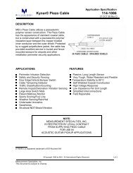
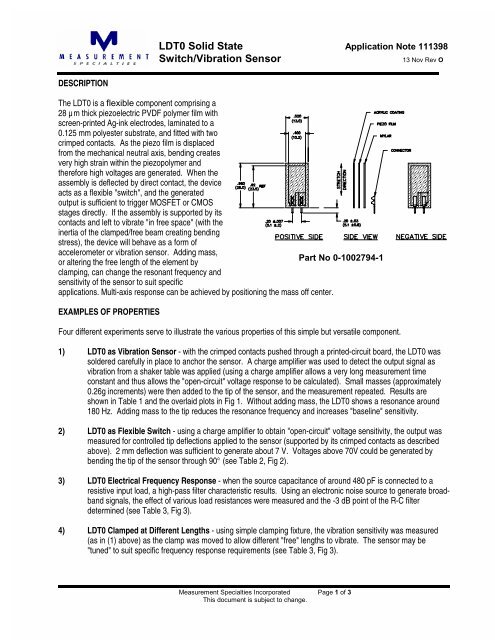
The <strong>LDT0</strong> is a flexible component comprising a<br />
28 µ m thick piezoelectric PVDF polymer film with<br />
screen-printed Ag-ink electrodes, laminated to a<br />
0.125 mm polyester substrate, and fitted with two<br />
crimped contacts. As the piezo film is displaced<br />
from the mechanical neutral axis, bending creates<br />
very high strain within the piezopolymer and<br />
therefore high voltages are generated. When the<br />
assembly is deflected by direct contact, the device<br />
acts as a flexible "switch", and the generated<br />
output is sufficient to trigger MOSFET or CMOS<br />
stages directly. If the assembly is supported by its<br />
contacts and left to vibrate "in free space" (with the<br />
inertia of the clamped/free beam creating bending<br />
stress), the device will behave as a form of<br />
accelerometer or vibration sensor. Adding mass,<br />
or altering the free length of the element by<br />
Part No 0-1002794-1<br />
clamping, can change the resonant frequency and<br />
sensitivity of the sensor to suit specific<br />
applications. Multi-axis response can be achieved by positioning the mass off center.<br />
EXAMPLES OF PROPERTIES<br />
Four different experiments serve to illustrate the various properties of this simple but versatile component.<br />
1) <strong>LDT0</strong> as <strong>Vibration</strong> <strong>Sensor</strong> - with the crimped contacts pushed through a printed-circuit board, the <strong>LDT0</strong> was<br />
soldered carefully in place to anchor the sensor. A charge amplifier was used to detect the output signal as<br />
vibration from a shaker table was applied (using a charge amplifier allows a very long measurement time<br />
constant and thus allows the "open-circuit" voltage response to be calculated). Small masses (approximately<br />
0.26g increments) were then added to the tip of the sensor, and the measurement repeated. Results are<br />
shown in Table 1 and the overlaid plots in Fig 1. Without adding mass, the <strong>LDT0</strong> shows a resonance around<br />
180 Hz. Adding mass to the tip reduces the resonance frequency and increases "baseline" sensitivity.<br />
2) <strong>LDT0</strong> as Flexible <strong>Switch</strong> - using a charge amplifier to obtain "open-circuit" voltage sensitivity, the output was<br />
measured for controlled tip deflections applied to the sensor (supported by its crimped contacts as described<br />
above). 2 mm deflection was sufficient to generate about 7 V. Voltages above 70V could be generated by<br />
bending the tip of the sensor through 90° (see Table 2, Fig 2).<br />
3) <strong>LDT0</strong> Electrical Frequency Response - when the source capacitance of around 480 pF is connected to a<br />
resistive input load, a high-pass filter characteristic results. Using an electronic noise source to generate broadband<br />
signals, the effect of various load resistances were measured and the -3 dB point of the R-C filter<br />
determined (see Table 3, Fig 3).<br />
4) <strong>LDT0</strong> Clamped at Different Lengths - using simple clamping fixture, the vibration sensitivity was measured<br />
(as in (1) above) as the clamp was moved to allow different "free" lengths to vibrate. The sensor may be<br />
"tuned" to suit specific frequency response requirements (see Table 3, Fig 3).<br />
Measurement Specialties Incorporated Page 1 of 3<br />
This document is subject to change.
<strong>LDT0</strong> <strong>Solid</strong> <strong>State</strong> Application Note 111398<br />
<strong>Switch</strong>/<strong>Vibration</strong> <strong>Sensor</strong><br />
TABLE I: <strong>LDT0</strong> as <strong>Vibration</strong> <strong>Sensor</strong> (see Fig 1)<br />
Added<br />
Mass<br />
TABLE II: <strong>LDT0</strong> as Flexible <strong>Switch</strong><br />
(see Fig 2)<br />
Tip<br />
Deflection<br />
Charge<br />
Output<br />
Baseline<br />
Sensitivity<br />
Sensitivity<br />
at Resonance<br />
Resonant<br />
Frequency<br />
Measurement Specialties Incorporated, Page 2 of 3<br />
This document is subject to change.<br />
+3 Db<br />
Frequency<br />
0 50 mV/g 1.4 V/g 180 Hz 90 Hz<br />
1 200 mV/g 4 V/g 90 Hz 45 Hz<br />
2 400 mV/g 8 V/g 60 Hz 30 Hz<br />
3 800 mV/g 16 V/g 40 Hz 20 Hz<br />
o/c Voltage<br />
Output<br />
2 mm 3.4 nC 7 V<br />
5 mm 7.2 nC 15 V<br />
10 mm 10 - 12 nC 20 - 25 V<br />
max (90�) > 30 nC > 70 V
TABLE III: <strong>LDT0</strong> Electrical Frequency Response<br />
(see Fig 3)<br />
(480 pF source capacitance)<br />
Load<br />
Resistance<br />
<strong>LDT0</strong> <strong>Solid</strong> <strong>State</strong> Application Note 111398<br />
<strong>Switch</strong>/<strong>Vibration</strong> <strong>Sensor</strong><br />
-3 db<br />
Frequency<br />
1 Megohm 330 Hz<br />
10 Megohm 33 Hz<br />
100 Megohm 3.3 Hz<br />
TABLE IV: <strong>LDT0</strong> Clamped at Different Lengths<br />
(see Fig 4)<br />
Length<br />
beyond<br />
clamp<br />
20 mm<br />
(no clamp)<br />
Resonant<br />
Frequency<br />
Settling<br />
Time (5 cyc)<br />
180 Hz 28 msec<br />
16 mm 250 Hz 20 msec<br />
11 mm 500 Hz 10 msec<br />
7 mm 1000 Hz 5 msec<br />
Measurement Specialties Incorporated, Page 3 of 3<br />
This document is subject to change.