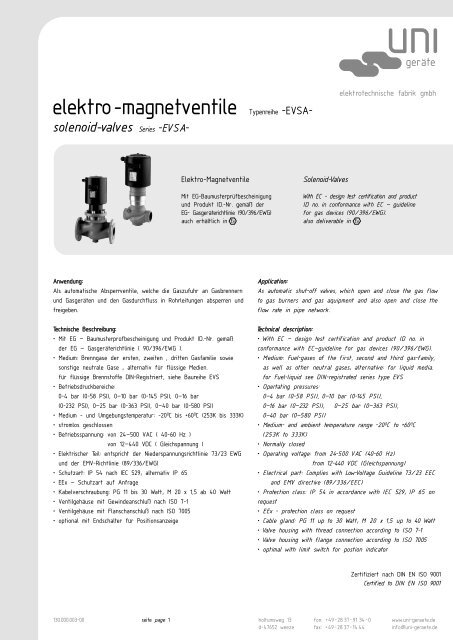
elektro-magnetventile Typenreihe -EVSA- - fh-teknik a/s
elektro-magnetventile Typenreihe -EVSA- - fh-teknik a/s
elektro-magnetventile Typenreihe -EVSA- - fh-teknik a/s

You also want an ePaper? Increase the reach of your titles
YUMPU automatically turns print PDFs into web optimized ePapers that Google loves.
<strong>elektro</strong>-<strong>magnetventile</strong> <strong>Typenreihe</strong> -<strong>EVSA</strong>solenoid-valves<br />
Series -<strong>EVSA</strong>-<br />
Anwendung:<br />
Als automatische Absperrventile, welche die Gaszufuhr an Gasbrennern<br />
und Gasgeräten und den Gasdurchfluss in Rohrleitungen absperren und<br />
freigeben.<br />
Technische echnische Beschr Beschreibung:<br />
• Mit EG — Baumusterprüfbescheinigung und Produkt ID.-Nr. gemäß<br />
der EG — Gasgeräterichtlinie ( 90/396/EWG ).<br />
• Medium: Brenngase der ersten, zweiten , dritten Gasfamilie sowie<br />
sonstige neutrale Gase ; alternativ für flüssige Medien.<br />
für flüssige Brennstoffe DIN-Registriert, siehe Baureihe EVS<br />
• Betriebsdruckbereiche:<br />
0-4 bar (0-58 PSI), 0—10 bar (0-145 PSI), 0—16 bar<br />
(0-232 PSI), 0—25 bar (0-363 PSI), 0—40 bar (0-580 PSI)<br />
• Medium - und Umgebungstemperatur: -200C bis +600C (253K bis 333K)<br />
• stromlos geschlossen<br />
• Betriebsspannung: von 24—500 VAC ( 40-60 Hz )<br />
von 12—440 VDC ( Gleichspannung )<br />
• Elektrischer Teil: entspricht der Niederspannungsrichtlinie 73/23 EWG<br />
und der EMV-Richtlinie (89/336/EWG)<br />
• Schutzart: IP 54 nach IEC 529; alternativ IP 65<br />
• EEx — Schutzart auf Anfrage<br />
• Kabelverschraubung: PG 11 bis 30 Watt; M 20 x 1,5 ab 40 Watt<br />
• Ventilgehäuse mit Gewindeanschluß nach ISO 7-1<br />
• Ventilgehäuse mit Flanschanschluß nach ISO 7005<br />
• optional mit Endschalter für Positionsanzeige<br />
130.000.003-00 seite page 1<br />
Elektro-Magnetventile<br />
Mit EG-Baumusterprüfbescheinigung<br />
und Produkt ID.-Nr. gemäß der<br />
EG- Gasgeräterichtlinie (90/396/EWG)<br />
auch erhältlich in<br />
holtumsweg 13<br />
d-47652 weeze<br />
Solenoid-Valves<br />
geräte<br />
<strong>elektro</strong>technische fabrik gmbh<br />
With EC - design test certification and product<br />
ID no. in conformance with EC — guideline<br />
for gas devices (90/396/EWG).<br />
also deliverable in<br />
Application:<br />
As automatic shut-off valves, which open and close the gas flow<br />
to gas burners and gas aquipment and also open and close the<br />
flow rate in pipe network.<br />
Technical echnical descr description:<br />
• With EC — design test certification and product ID no. in<br />
conformance with EC—guideline for gas devices (90/396/EWG).<br />
• Medium: Fuel-gases of the first, second and third gas-family,<br />
as well as other neutral gases; alternative: for liquid media.<br />
for Fuel-liquid see DIN-registrated series type EVS<br />
• Opertating pressures:<br />
0—4 bar (0-58 PSI), 0—10 bar (0-145 PSI),<br />
0—16 bar (0—232 PSI), 0—25 bar (0—363 PSI),<br />
0—40 bar (0—580 PSI)<br />
• Medium- and ambient temperature range -200C to +600C (253K to 333K)<br />
• Normally closed<br />
• Operating voltage: from24-500 VAC (40-60 Hz)<br />
from12-440 VDC (Gleichspannung)<br />
• Electrical part: Complies with Low-Voltage Guideline 73/23 EEC<br />
and EMV directive (89/336/EEC)<br />
• Protection class: IP 54 in accordance with IEC 529; IP 65 on<br />
request<br />
• EEx - protection class on request<br />
• Cable gland: PG 11 up to 30 Watt; M 20 x 1,5 up to 40 Watt<br />
• Valve housing with thread connection according to ISO 7-1<br />
• Valve housing with flange connection according to ISO 7005<br />
• optimal with limit switch for postion indicator<br />
fon: +49-28 37-91 34-0<br />
fax: +49-2837-1444<br />
Zertifiziert nach DIN EN ISO 9001<br />
Certified to DIN EN ISO 9001<br />
www.uni-geraete.de<br />
info@uni-geraete.de
Hauptmerkmale<br />
• Anforderungen gemäß der Gasgeräterichtlinie<br />
(90/396/EWG), Automatische Absperrventile Ventilklasse<br />
A, Gruppe 2<br />
Prüfgrundlage :<br />
4bar (58 PSI); DIN EN 161; 10bar (145 PSI) ; DIN<br />
3391, DIN 3394 Teil 1; 25bar (363 PSI) ; DIN EN<br />
161, DIN 3394 Teil 1; 40bar (580 PSI) ; DIN EN<br />
161, DIN 3391, DIN 3394 Teil 1<br />
• Ventilgehäuse mit Gewindeanschluß nach ISO 7-1<br />
[Rp 1/4 bis Rp 3/4 aus G-CuSn5ZnPb (Rg 5)];<br />
40bar (580 PSI), Rp 1/2 Ausführung aus 1.4571<br />
[Rp 1 bis Rp 2 aus EN-JL 1040 (GG25)]<br />
-alternativ 1.4571 oder 1.4408<br />
• Ventilgehäuse mit Flanschanschluß nach ISO 7005<br />
[DN 15—DN 150; EN-JL 1040 (GG25)]; ab 10 (145<br />
PSI) bar Ausführung aus EN-JS 1049 (GGG 40.3)<br />
-alternativ GP240GH (GS-C25N) ; 1.4408/ 1.4581<br />
-andere Bohrbilder auf Anfrage<br />
• Die Sicherheitsabsperreinrichtungen sind stopfbuchslos,<br />
direkt gesteuert, und arbeiten geräuscharm.<br />
• Geringer Druckverlust durch Freistromventilgehäuse.<br />
• Die Abdichtung erfolgt durch weichelastischen<br />
Dichtungswerkstoff (geeignet für Brenngase der<br />
ersten, zweiten und dritten Gasfamilie.)<br />
• Zuverlässige Dichtheit zur Atmosphäre durch Lippen—<br />
und O-Ringe.<br />
• Alle Innenteile, die nicht aus NE— Metallen bzw.<br />
Edelstahl bestehen, sind mit Spezialrostschutz<br />
behandelt.<br />
• Gleichstrom — Magnetspule mit zusätzlich aufgebauten<br />
Varistoren, schutzbeschaltet gegen beim Abschalten<br />
auftretende Induktionsspannungen und aus dem Netz<br />
auftretende Spitzenspannungen.<br />
• Schalthäufigkeit: max. 1500 Schaltspiele/h bei Elektro<br />
— Magnetventile ohne Anzug — und Haltewicklung,<br />
max. 20 Schaltspiele/h im Dauerbetrieb bei Elektro<br />
— Magnetventile mit Anzug— und Haltewicklung.<br />
• Lange Lebensdauer durch bewährte Bauelemente<br />
und Baugrößen..<br />
Funktionsbeschreibung<br />
Öffnungsvorgang:<br />
Beim Anlegen der Betriebsspannung zieht der Magnetkern<br />
gegen den Druck des Mediums und der Dichtkraft der<br />
Druckfeder.Die Ventilspindel hebt vom Ventilsitz ab,<br />
und gibt den Querschnitt innerhalb von 0,3 — 0,7 sec.<br />
völlig frei. Das Elektro — Magnetventil bleibt solange<br />
geöffnet, wie die Betriebsspannung ansteht. Die Erwärmung<br />
des Magnetgehäuses im Dauerbetrieb beträgt 60 0 C (333<br />
K).<br />
Schliessvorgang:<br />
Nach Abschalten der Betriebsspannung wird der<br />
Magnetkern mit der Ventilspindel durch die Schließkraft<br />
der Druckfeder innerhalb kleiner 1 sec. auf den<br />
Ventilsitz gepreßt und sperrt den Gasdurchfluß dicht<br />
ab.<br />
holtumsweg 13<br />
d-47652 weeze<br />
fon: +49-28 37-91 34-0<br />
fax: +49-2837-1444<br />
www.uni-geraete.de<br />
info@uni-geraete.de<br />
Main ain Characteristics<br />
C<br />
• Requirements in accordance with the EC Gas Apparatus<br />
Guideline (90/396/EEC),Automatic Safety Shut-off Valve,<br />
valve class A,Group 2<br />
Check basis:<br />
4bar (58 PSI) ; DIN EN 161; 10 bar (145 PSI);<br />
DIN 3391,DIN 3394 part 1,25 bar (363 PSI);<br />
DIN EN 161,DIN 3394 part 1,40 bar (580 PSI); DIN<br />
EN 161,DIN 3391,DIN 3394 part 1<br />
• Valve housing with thread connection according to<br />
ISO 7-1<br />
[Rp 1/4 to Rp 3/4 made of G-CuSn5ZnPb (Rg 5)] ;<br />
40bar (580 PSI),Rp 1/2 configuration with 1.4571<br />
[Rp 1 to Rp 2 with EN-JL 1040 (GG25)]<br />
-alternatively made of 1.4571 or 1.4408<br />
• Flanged valve housing with flange connection in conformance<br />
with ISO 7005 [DN 15 — DN 150; EN-JL 1040 (GG25)];<br />
ab 10 (145 PSI) bar configuration with EN-JS 1049 (GGG<br />
40.3) - alternatively GP240GH (GS-C25N) ; 1.4408/ 1.4581<br />
-further boring-schemes on request<br />
• The safety shut-off-devices are without seal-package and<br />
directly controlled (Low pressure drop using non-clogging<br />
valve body.<br />
• Sealing is accomplished with soft elastic sealing compound<br />
• suited for fuel gases of the first,second,and third gas<br />
families)<br />
• Reliable tightness towards atmosphere using lipseals and<br />
o-rings.<br />
• All internal parts which are not of non ferrous metals or<br />
stainless steel have a special corrosion protection coating<br />
• Direct-current magnet-coil,protective-wired against inductionstrain<br />
when switching-off and against peak-voltages<br />
• Switching rate of electromagnetic valves without pickup<br />
and holding winding: 1500 cycles/h max.,switching rate<br />
cintinuously operating electromagnetic valves equipped with<br />
pickup and holding winding: 20 cycles/h max..<br />
• Remakable durability by using approved components and<br />
sizes.<br />
Description of Func<br />
ion of Function<br />
Opening procedure:<br />
When the operating voltage is switched on,the solenoid core<br />
pulls the valve spindle together with the valve disc out of<br />
valve seat aggainst the pressure of the medium and the<br />
closing force of the pressure spring,thereby opening the<br />
full cross-section within 0,3 — 0,7 seconds, depending on<br />
the size of the automatic saftey shut-off valve 60 0 C (333<br />
K).<br />
Closing procedure:<br />
When the Operating voltage is switched off,the solenoid cire<br />
with the valve spindle and valve disc is pressed into the<br />
valve seat by the force of the pressure spring,thereby<br />
shutting off the gas flow in less than 1 second ,depending<br />
on the size of the automatic shut-off valve.<br />
seite page 2
Montage age — Rich Richtlinien<br />
• Arbeiten am Elektro — Magnetventil dürfen nur von Fachpersonal<br />
durchgeführt werden.<br />
• Vor der Installation der Elektro-Magnetventile die Montage<br />
Richtlinien lesen. Die Elektro-Magnetventile müssen nach<br />
den geltenden Vorschriften installiert werden.<br />
• Der Einbau des Elektro-Magnetventiles muß in der durch<br />
einem am Ventilgehäuse befindlichen Pfeil angegebenen<br />
Durchflußrichtung erfolgen.<br />
• Bei Elektro-Magnetventilen ohne den Bestellzusatz „W” ist<br />
darauf zu achten, daß der Einbau in die Rohrleitung mit<br />
senkrecht stehendem Magnetgehäuse erfolgt. Eine Schräglage<br />
von max. 5o ist zulässig. Bei Elektro — Magnetventilen mit<br />
dem Bestellzusatz „W” kann der Einbau in vertikale oder<br />
horizontale Rohrleitung mit liegendem Magnetgehäuse erfolgen.<br />
• Die Rohrleitungen sind vor dem Einbau des Elektro-Magnetventils<br />
gründlich zu säubern.<br />
• Flanschflächen schützen. Schrauben kreuzweise anziehen. Auf<br />
mechanisch spannungsfreien Einbau achten.<br />
• Niemals Arbeiten durchführen, wenn Gasdruck oder elektrische<br />
Spannung anliegt. Offenes Feuer vermeiden. Öffentliche<br />
Vorschriften beachten.<br />
• Nach Einbau äußere Dichtheit prüfen. (Bei Nichtbeachtung<br />
der Hinweise sind Personen — oder Sachfolgeschäden denkbar.<br />
Flanschanschluß:<br />
• Ist am Eingang des Elektro-Magnetventils kein Schmutzfänger<br />
angebracht, so ist dafür Sorge zu tragen, daß ein geeigneter<br />
Schmutzfänger in nicht zu großer Entfernung vor dem Eingang<br />
des Ventils installiert wird. Die lichten Weiten der Öffnungen<br />
des Siebes dürfen nicht größer sein als 1,5 mm und sie<br />
dürfen einen 1 mm Prüfdorn nicht durchlassen. Bei zwei zu<br />
einer Gruppe montierten Elektro — Magnetventilen genügt<br />
eine vor das erste Elektro — Magnetventil angebrachter<br />
Schmutzfänger.<br />
Der Schmutzfänger soll das Eindringen von Fremdkörpern<br />
verhindern.<br />
Falls kein Schmutzfänger vorhanden ist, muß dieser mitbestellt<br />
werden, da ansonsten die Produkt-ID-Nr. ihre Gültigkeit<br />
verliert.<br />
Bestellzusätze<br />
• Bestellzusätze entnehmen Sie bitte unserem Typenschlüssel.<br />
seite page 3<br />
Installation ion GGuidelines<br />
• Work on solenoid valve may only be performed by special<br />
staff.<br />
• Read the installation instructions before installing the<br />
solenoid valve. The solenoid valve must be installed in<br />
accordance with the applicable regulations.<br />
• The solenoid valve must be installed in the flow direction<br />
indicated by the arrow on the valve housing. (Solenoid<br />
valves without ordering „W”, make sure to install the unit<br />
in the pipeline with mahnet housing in vertical position.<br />
A max. 5 inclined is admissible. (Solenoid valves with<br />
ordering „W”install the unitlgen.<br />
• The pipelines must be thoroughly cleaned before the<br />
automatic safety shut-off valve is installed.<br />
• Protect flange surfaces. Fasten screws crosswise. See to<br />
installation that has to be mechanical-strainless.<br />
• Do not do any installation work when there is gas-pressure<br />
or electrical voltage. Avoid open fire. Observe public rules.<br />
• After installation check external tightness. (The Nonobservation<br />
of warning indications may cause damage to<br />
property or injure persons.<br />
Flanged connection:<br />
• If no dirt trap is installed at/in the inlet to the valve,<br />
care must be taken that a suitable dirt trap is installed<br />
not too far upstream of the valve inlet. The mesh width<br />
of the openings of the screen must not exceed 1.5 mm<br />
and must not permit a test mandrel of 1 mm diametet<br />
to pass.<br />
The dirt trap is intended to prevent the entry of foreign<br />
particles.<br />
In case of absence of the dirt trap, this one has to be<br />
ordered togehter with the safety shut-off devices. Otherwise,<br />
the product-ID-number will no longer be valid.<br />
Order der Suffixes S fixes<br />
For ordersuffixes, please refer to our type code.<br />
holtumsweg 13<br />
d-47652 weeze<br />
fon: +49-28 37-91 34-0<br />
fax: +49-2837-1444<br />
www.uni-geraete.de<br />
info@uni-geraete.de
GEWINDEAUSFÜHRUNG THREAD DESIGN<br />
holtumsweg 13<br />
d-47652 weeze<br />
fon: +49-28 37-91 34-0<br />
fax: +49-2837-1444<br />
www.uni-geraete.de<br />
info@uni-geraete.de<br />
seite page 4
GEWINDEAUSFÜHRUNG THREAD DESIGN<br />
Typ<br />
Type<br />
<strong>Typenreihe</strong> Series 0-4 bar / 0 - 58 PSI<br />
4-<strong>EVSA</strong> 2 -4 Rp 1/4<br />
15<br />
4-<strong>EVSA</strong><br />
4-<strong>EVSA</strong><br />
4-<strong>EVSA</strong><br />
4-<strong>EVSA</strong><br />
4-<strong>EVSA</strong><br />
4-<strong>EVSA</strong><br />
4-<strong>EVSA</strong><br />
3 -4<br />
5 -4<br />
7 -4<br />
10 -4<br />
12 -4<br />
15 -4<br />
20 -4<br />
Anschluß und Durchgang<br />
Connection/bore<br />
Rp 3/8<br />
Rp 1/2<br />
Rp 3/4<br />
Rp 1<br />
Rp 1 1/4<br />
Rp 1 1/2<br />
Rp 2<br />
seite page 5<br />
Leistung in Watt<br />
Capacity in watt<br />
<strong>Typenreihe</strong> Series 0-40 bar / 0 - 580 PSI<br />
40-<strong>EVSA</strong> 5-4.04.29 *1 Rp 1/2<br />
50<br />
30<br />
30<br />
30<br />
40<br />
50<br />
70<br />
90<br />
Gewichtinkg<br />
Weight in kg<br />
2,5<br />
5,4<br />
5,6<br />
6,0<br />
9,4<br />
15,1<br />
18,6<br />
27,5<br />
10,7<br />
A<br />
Baumaße<br />
Dimensions<br />
B oC<br />
60<br />
80<br />
80<br />
95<br />
105<br />
120<br />
150<br />
170<br />
80<br />
190<br />
220<br />
220<br />
220<br />
260<br />
290<br />
345<br />
380<br />
220<br />
85<br />
106<br />
106<br />
106<br />
119<br />
128<br />
138<br />
150<br />
128<br />
holtumsweg 13<br />
d-47652 weeze<br />
Produkt ID-Nummer<br />
Product identification no.<br />
CE-0085 AQ 0256<br />
CE-0085 AQ 0256<br />
CE-0085 AQ 0256<br />
CE-0085 AQ 0256<br />
CE-0085 AQ 0256<br />
CE-0085 AQ 0256<br />
CE-0085 AQ 0256<br />
CE-0085 AQ 0256<br />
CE-0085 AQ 0986<br />
Bitte gesonderte Zeichnung anfordern: *1 = S 5772 Please send for separate drawing *1 = S 5772<br />
Achtung! Alle angegebenen elektrischen Leistungen gelten für den Dauerbetrieb. Die elektrischen Leistungen für den Anfahrbetrieb liegen ca. 25% höher.<br />
Attention! All indicated electrical power is provided for continuous working. The electrical power for the starting is approx. 25% higher.<br />
Pos / Item<br />
100<br />
103<br />
105<br />
106<br />
108<br />
220<br />
206<br />
207<br />
210<br />
221<br />
213<br />
214<br />
215<br />
216<br />
(400)<br />
402<br />
(403/X)<br />
(404)<br />
500<br />
501<br />
503<br />
504<br />
*700<br />
**701<br />
702<br />
900/X<br />
901<br />
902<br />
903<br />
905<br />
908/X<br />
Benennung<br />
Ventilgehäuse<br />
Magnetgehäuse<br />
Magnetgehäusedeckel<br />
Gehäuseoberteil<br />
Gehäuseflansch<br />
Ausgleichskolben<br />
Führungsring<br />
Magnetkern<br />
Federbolzen<br />
Kolbenführung<br />
Gewindering<br />
Ventilstift<br />
Tellerschraube<br />
Verbindungsstück<br />
nurbei Endschalteranbau<br />
Ventiltellerdichtung<br />
Flachdichtung<br />
O-Ring<br />
Lippenring<br />
Magnetplatte<br />
Verbindungsbolzen<br />
Druckfeder<br />
Zylindersieb<br />
Si-Gleichrichtersatz<br />
entfällt bei Gleichstromausführung<br />
Kabelverschraubung<br />
Magnetspule<br />
Sechskantschraube<br />
Sechskantmutter<br />
Bolzen<br />
Kerbstift<br />
Federring<br />
Sicherungsblech<br />
Description<br />
Valve housing<br />
Solenoid housing<br />
Solenoid housing cover<br />
Housing top section<br />
Housing flange<br />
Balance piston<br />
Guide ring<br />
Magnet core<br />
Spring bolt<br />
Piston guide<br />
Threaded ring<br />
Valve pin<br />
Plate bolt<br />
Connection piece<br />
only by limit switch mounting<br />
Valve disc seal<br />
Flat seal<br />
O-ring<br />
Lip-ring<br />
Magnet plate<br />
Connecting bolt<br />
Compression spring<br />
Cylindrical sieve<br />
Si rectifier assembly<br />
not used on DC mode<br />
Cable gland<br />
Magnetic coil<br />
Hexagonal bolt<br />
Hexagonal nut<br />
Bolt<br />
Cotter pin<br />
Lock washer<br />
Locking plate<br />
* = entfällt bei Elektro-Magnetventilen mit dem Bestellzusatz A5 bzw.<br />
Av und bei Schutzart IP 65<br />
** = wird bei Schutzart IP 65 ersetzt durch Hirschmann- Steckverbinder<br />
nach DIN 43650A mit integrierter Gleichrichterplatine.<br />
- Meßanschluß Rp 1/4 bei Gewindeventilgehäusen<br />
Rp 1 - Rp 2 serienmäßig<br />
Rp 3/8 - Rp 3/4 (nur auf Wunsch)<br />
* = not applicable with solenoid valves with order suffix A5, Av<br />
respectively and by protectiv guard IP 65<br />
**= will be replaced by a Hirschmann connector DIN 43650A with<br />
integrated rectifier board in case of IP 65 protection system.<br />
- Connection thread Rp 1/4 by flange valve bodies<br />
Rp 1 - Rp 2 standard<br />
Rp 3/8 - Rp 3/4 (by request only)<br />
( ) =Verschleißteile / Wear parts<br />
fon: +49-28 37-91 34-0<br />
fax: +49-2837-1444<br />
www.uni-geraete.de<br />
info@uni-geraete.de
FLANSCHAUSFÜHRUNG FLANGE DESIGN<br />
holtumsweg 13<br />
d-47652 weeze<br />
fon: +49-28 37-91 34-0<br />
fax: +49-2837-1444<br />
www.uni-geraete.de<br />
info@uni-geraete.de<br />
seite page 6
FLANSCHAUSFÜHRUNG FLANGEDESIGN<br />
Typ<br />
Type<br />
4-<strong>EVSA</strong><br />
4-<strong>EVSA</strong><br />
4-<strong>EVSA</strong><br />
4-<strong>EVSA</strong><br />
4-<strong>EVSA</strong><br />
4-<strong>EVSA</strong><br />
4-<strong>EVSA</strong><br />
4-<strong>EVSA</strong><br />
4-<strong>EVSA</strong><br />
4-<strong>EVSA</strong><br />
4-<strong>EVSA</strong><br />
10-<strong>EVSA</strong><br />
10-<strong>EVSA</strong><br />
10-<strong>EVSA</strong><br />
10-<strong>EVSA</strong><br />
10-<strong>EVSA</strong><br />
10-<strong>EVSA</strong><br />
10-<strong>EVSA</strong><br />
10-<strong>EVSA</strong><br />
10-<strong>EVSA</strong><br />
10-<strong>EVSA</strong><br />
10-<strong>EVSA</strong><br />
16-<strong>EVSA</strong><br />
16-<strong>EVSA</strong><br />
5NH—4 …<br />
7NH—4 …<br />
10NH—4 …<br />
12NH—4 …<br />
15NH—4 …<br />
20NH—4 …<br />
25NH—4 …<br />
30NH—4A5 … 1)<br />
100H—4Av … 1)<br />
125H—4Av … 2)<br />
150H—4Av … 2)<br />
5NH—4 …<br />
7NH—4 …<br />
10NH—4 …<br />
12NH—4A5 … 1)<br />
15NH—4A5 … 1)<br />
20NH—4A5 … 1)<br />
25NH—4A5 … 1)<br />
30NH—4Av … 2)<br />
100H—4Av … 2)<br />
125H—4Av … 2)<br />
150H—4Av … 2)<br />
10H(N)—4 … 2)<br />
15H(N)—4 … 2)<br />
25-<strong>EVSA</strong> 20NH—4A5 *3/1)<br />
Anschluß und<br />
Durchgang<br />
Connection/bore<br />
<strong>Typenreihe</strong> Series 0-4 bar / 0 - 58 PSI<br />
DN 15<br />
DN 20<br />
DN 25<br />
DN 32<br />
DN 40<br />
DN 50<br />
DN 65<br />
DN 80<br />
DN100<br />
DN125<br />
DN150<br />
DN 15<br />
DN 20<br />
DN 25<br />
DN 32<br />
DN 40<br />
DN 50<br />
DN 65<br />
DN 80<br />
DN100<br />
DN125<br />
DN150<br />
DN 25<br />
DN 40<br />
DN 25<br />
seite page 7<br />
Leistung in Watt<br />
Capacity in watt<br />
<strong>Typenreihe</strong> Series 0-10 bar / 0 - 145 PSI<br />
<strong>Typenreihe</strong> Series 0-16 bar / 0 - 232 PSI<br />
<strong>Typenreihe</strong> Series 0-25 bar / 0 - 363 PSI<br />
Pos / Item<br />
100<br />
103<br />
105<br />
106<br />
108<br />
220<br />
206<br />
207<br />
210<br />
221<br />
213<br />
214<br />
215<br />
216<br />
(400)<br />
402<br />
(403/X)<br />
(404)<br />
500<br />
501<br />
503<br />
504<br />
*700<br />
**701<br />
702<br />
900/X<br />
901<br />
902<br />
903<br />
905<br />
908/X<br />
Benennung<br />
Ventilgehäuse<br />
Magnetgehäuse<br />
Magnetgehäusedeckel<br />
Gehäuseoberteil<br />
Gehäuseflansch<br />
Ausgleichskolben<br />
Führungsring<br />
Magnetkern<br />
Federbolzen<br />
Kolbenführung<br />
Gewindering<br />
Ventilstift<br />
Tellerschraube<br />
Verbindungsstück<br />
nurbei Endschalteranbau<br />
Ventiltellerdichtung<br />
Flachdichtung<br />
O-Ring<br />
Lippenring<br />
Magnetplatte<br />
Verbindungsbolzen<br />
Druckfeder<br />
Zylindersieb<br />
Si-Gleichrichtersatz<br />
entfällt bei Gleichstromausführung<br />
Kabelverschraubung<br />
Magnetspule<br />
Sechskantschraube<br />
Sechskantmutter<br />
Bolzen<br />
Kerbstift<br />
Federring<br />
Sicherungsblech<br />
Description<br />
30<br />
30<br />
40<br />
50<br />
70<br />
90<br />
125<br />
200/20<br />
900/70<br />
900/70<br />
1200/120<br />
30<br />
30<br />
40<br />
200/20<br />
200/20<br />
200/20<br />
200/20<br />
900/70<br />
900/70<br />
1200/120<br />
1200/120<br />
125<br />
125<br />
200/20<br />
Valve housing<br />
Solenoid housing<br />
Solenoid housing cover<br />
Housing top section<br />
Housing flange<br />
Balance piston<br />
Guide ring<br />
Magnet core<br />
Spring bolt<br />
Piston guide<br />
Threaded ring<br />
Valve pin<br />
Plate bolt<br />
Connection piece<br />
only by limit switch mounting<br />
Valve disc seal<br />
Flat seal<br />
O-ring<br />
Lip-ring<br />
Magnet plate<br />
Connecting bolt<br />
Compression spring<br />
Cylindrical sieve<br />
Si rectifier assembly<br />
not used on DC mode<br />
Cable gland<br />
Magnetic coil<br />
Hexagonal bolt<br />
Hexagonal nut<br />
Bolt<br />
Cotter pin<br />
Lock washer<br />
Locking plate<br />
Gewichtinkg<br />
Weight in kg<br />
9<br />
9<br />
14<br />
21<br />
24<br />
33<br />
50<br />
62<br />
74<br />
122<br />
135<br />
9<br />
9<br />
14<br />
21<br />
24<br />
33<br />
50<br />
66<br />
74<br />
124<br />
135<br />
34<br />
43<br />
50<br />
A<br />
Baumaße<br />
Dimensions<br />
B oC<br />
130<br />
150<br />
160<br />
180<br />
200<br />
230<br />
290<br />
310<br />
350<br />
400<br />
480<br />
130<br />
150<br />
160<br />
180<br />
200<br />
230<br />
290<br />
310<br />
350<br />
400<br />
480<br />
160<br />
200<br />
230<br />
242<br />
242<br />
245<br />
315<br />
350<br />
380<br />
400<br />
440<br />
470<br />
520<br />
560<br />
242<br />
242<br />
245<br />
315<br />
350<br />
380<br />
400<br />
440<br />
470<br />
520<br />
560<br />
441<br />
447<br />
436<br />
106<br />
106<br />
119<br />
128<br />
138<br />
150<br />
175<br />
183<br />
175<br />
175<br />
183<br />
106<br />
106<br />
119<br />
128<br />
138<br />
150<br />
183<br />
183<br />
175<br />
183<br />
183<br />
175<br />
175<br />
183<br />
holtumsweg 13<br />
d-47652 weeze<br />
Produkt ID-Nummer<br />
Product identification no.<br />
CE-0085 AQ 0256<br />
CE-0085 AQ 0256<br />
CE-0085 AQ 0256<br />
CE-0085 AQ 0256<br />
CE-0085 AQ 0256<br />
CE-0085 AQ 0256<br />
CE-0085 AQ 0256<br />
CE-0085 AQ 0256<br />
CE-0085 AQ 0256<br />
CE-0085 AQ 0256<br />
CE-0085 AQ 0256<br />
CE-0085 BL 0510<br />
CE-0085 BL 0510<br />
CE-0085 BL 0510<br />
CE-0085 BL 0510<br />
CE-0085 BL 0510<br />
CE-0085 BL 0510<br />
CE-0085 BL 0510<br />
CE-0085 BL 0510<br />
CE-0085 BL 0510<br />
CE-0085 BL 0510<br />
CE-0085 BL 0510<br />
CE-0085 AR 0411<br />
CE-0085 AR 0411<br />
CE-0085 AS 0559<br />
*2 - *3 Bitte gesonderte Zeichnung anfordern: *2= S 4891-1; *3= S 5044-1<br />
*2 - *3 Please send for separate drawing: *2= S 4891-1; *3= S 5044-1<br />
1) = Magnetspule mit Anzug — und Haltewicklung serienmäßig mit integrierter Transisterschaltung<br />
Typ: TS 200 (in 24VDC , 110VAC , 230VAC lieferbar)<br />
2) = Magnetspule mit Anzug — und Haltewicklung serienmäßig mit integrierter Relaiskombination<br />
Typ: RKS 1-1500 (in 24VDC , 110VAC , 230VAC lieferbar)<br />
Andere Anschlußspannungen auf Anfrage<br />
1) = Magnetic coil with pickup and holding winding in series with integrated transistorized<br />
circuit Type: TS 200 (in 24VDC , 110VAC , 230 VAC deliverable)<br />
2) = Magnetic coil with pickup and holding winding in series with integrated relais combination<br />
Type: RKS 1-1500 (in 24VDC , 110VAC , 230 VAC deliverable)<br />
Other mains voltages on demand<br />
* = entfällt bei Elektro-Magnetventilen mit dem Bestellzusatz A5 bzw. Av und bei<br />
Schutzart IP 65<br />
** = wird bei Schutzart IP 65 ersetzt durch Hirschmann- Steckverbinder nach DIN 43650A<br />
mit integrierter Gleichrichterplatine.<br />
- Meßanschluß bei Flanschventilgehäusen auf Anfrage<br />
* = not applicable with solenoid valves with order suffix A5, Av respectively and by<br />
protectiv guard IP 65<br />
** = will be replaced by a Hirschmann connector DIN 43650A with integrated rectifier<br />
board in case of IP 65 protection system.<br />
- Connection thread Rp 1/4 by flange valve bodies on request<br />
( ) =Verschleißteile / Wear parts<br />
Achtung! Alle angegebenen Leistungen gelten fürden Dauerbetrieb. Die Leistungen fürden<br />
Anfahrbetrieb liegen ca. 25% höher.<br />
Änderungen an Maßen und Darstellungen, die dem technischen Fortschritt dienen, behalten<br />
wiruns vor.<br />
Attention! All indicated electrical power is provided for continuous working. The power for<br />
starting is approx. 25% higher.<br />
Alterations to dimensions and illustration in line with technical progress reserved.<br />
fon: +49-28 37-91 34-0<br />
fax: +49-2837-1444<br />
www.uni-geraete.de<br />
info@uni-geraete.de
Notizen Note<br />
holtumsweg 13<br />
d-47652 weeze<br />
Lieferprogramm Production programme<br />
<strong>elektro</strong>-<strong>magnetventile</strong><br />
<strong>elektro</strong>-pneumatikventile<br />
mengen-regelklappen<br />
mengen-regelschieber<br />
mengen-einstellarmaturen<br />
sonderarmaturen<br />
fon: +49-28 37-91 34-0<br />
fax: +49-2837-1444<br />
www.uni-geraete.de<br />
info@uni-geraete.de<br />
seite page 8<br />
electro-magnetic-valves<br />
electro-pneumatic-valves<br />
volume-regulating-butterfly-valves<br />
flow-control-valves<br />
flow-adjusting-valves<br />
special fittings<br />
geräte<br />
<strong>elektro</strong>technische fabrik gmbh